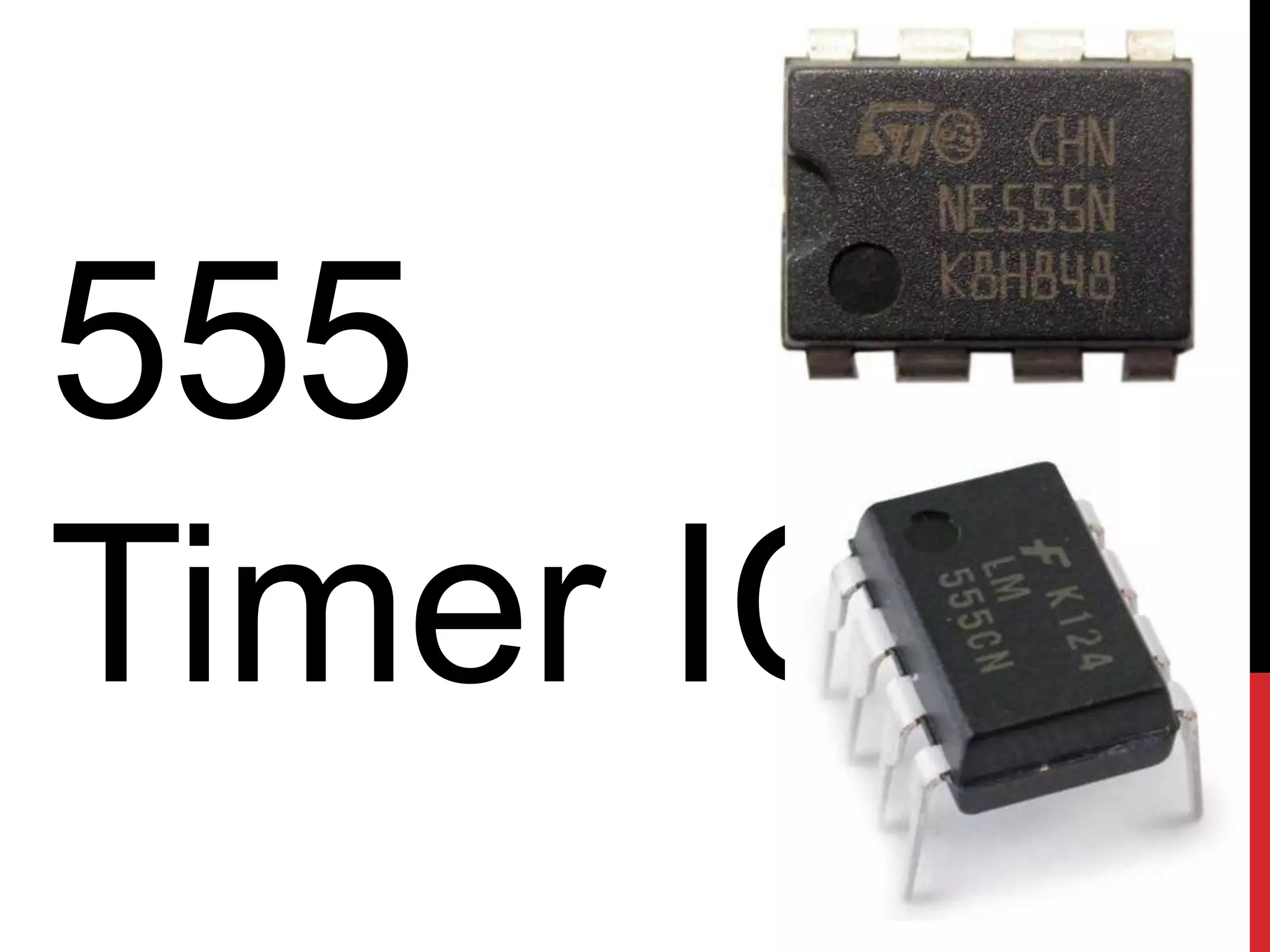
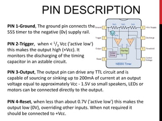
555
Timer IC
INTRODUCTION
• Introduced by Signetics in 1972, most popular is NE555 by
  STM electronics and Fairchild Semiconductor.
• The 555 timer IC is an integrated circuit (chip) used in a
  variety of timer, pulse generation, and oscillator applications.
• The 555 is used to provide time delays, as an oscillator, and
  as a flip-flop element.
• It gets its name from the three 5k ohm resistors which give
  the two comparators reference voltage.
• Depending on the manufacturer, the standard 555 package
  includes 25 transistors, 2 diodes and 15 resistors on a silicon
  chip installed in an 8-PIN DIP (Dual in-line) package.
• It is available in low power CMOS type ICM7555 package and
  556 Dual Timer (14 pin) with two timer in one IC and 558
  which is Quad timer.
INTERNAL LAYOUT
VOLTAGE DIVIDER


             2/3 Vcc


             1/3 Vcc
VOLTAGE COMPARATOR
Whenever the voltage is higher at the + input, the output value is +.
The output is 0 volts under all other conditions.
THE FLIP-FLOP
THE DISCHARGE TRANSIST
THE OUTPUT BUFFER
PIN DESCRIPTION
PIN 1-Ground, The ground pin connects the
555 timer to the negative (0v) supply rail.

PIN 2-Trigger, when < 1/3 Vcc ('active low')
this makes the output high (+Vcc). It
monitors the discharging of the timing
capacitor in an astable circuit.

PIN 3-Output, The output pin can drive any TTL circuit and is
capable of sourcing or sinking up to 200mA of current at an output
voltage equal to approximately Vcc - 1.5V so small speakers, LEDs or
motors can be connected directly to the output.

PIN 4-Reset, when less than about 0.7V ('active low') this makes the
output low (0V), overriding other inputs. When not required it
should be connected to +Vcc.
PIN DESCRIPTION
PIN 5-Control Voltage, this can be used to
adjust the threshold voltage which is set
internally to be 2/3 Vcc. Usually this function is
not required and the control input is
connected to 0V with a 10nF capacitor to
eliminate electrical noise.

PIN 6-Threshold, when > 2/3 Vcc ('active high')
this makes the output low (0V)*. It monitors
the charging of the timing capacitor in astable
and monostable circuits.
PIN 7-Discharge, The discharge pin is connected directly to the Collector
of an internal NPN transistor which is used to "discharge" the timing
capacitor to ground when the output at pin 3 switches "LOW".

PIN 8-Supply +Vcc, This is the power supply pin and for general purpose
TTL 555 timers is between 4.5V and 15V (18V Absolute Maximum).
MODES OF OPERATION
The 555 Timer IC has three modes of operation:

MONOSTABLE: in this mode, the 555 functions as a "one-shot"
pulse generator. Applications include timers, bounce free switches,
touch switches, frequency divider and so on.

BISTABLE: the 555 can operate as a flip-flop, if the DIS pin is not
connected and no capacitor is used. Uses include bounce-free
latched switches.

ASTABLE, the free running mode: the 555 can operate as an
oscillator. Uses include LED and lamp flashers, pulse generation,
logic clocks, tone generation, security alarms, pulse position
modulation and so on. The 555 can be used as a simple ADC,
converting an analog value to a pulse length.
MONOSTABLE MODE
In the monostable mode, the 555 timer
acts as a “single" pulse generator.
                      The pulse begins when the 555 timer receives
                      a signal at the trigger input that falls below a
                      third of the voltage supply.
The width of the output pulse is determined by
the time constant of an RC network, which
consists of a capacitor (C) and a resistor (R).
                      The output pulse ends when the voltage on
                      the capacitor equals 2/3 of the supply
                      voltage. The output pulse width can be
                      lengthened or shortened to the need of the
                      specific application by adjusting the values of
                      R and C.
MONOSTABLE MODE CIRCUIT DI
                                     The output pulse width of
                                     time t, which is the time it
                                     takes to charge C to 2/3 of
                                     the supply voltage, is given
                                     by
                                           t=RC ln(3)
                                     where t is in seconds, R is
                                     in ohms and C is in farads.

                                      While using the timer IC in
                                      monostable mode, the
main disadvantage is that the time span between any two triggering
pulses must be greater than the RC time constant.
BISTABLE MODE
In bistable mode, the 555 timer acts as a
flip-flop. The trigger and reset
Inputs are held high via Pull-up resistors
while the threshold input is simply
grounded. Thus configured, pulling
the trigger momentarily to ground acts as
a 'set' and transitions the output pin to
Vcc (high state). Pulling the reset input to
ground acts as a 'reset‘ and transitions
the output pin to ground (low state). No
capacitors are required in a bistable
configuration. Pin 5 (control) is
connected to ground via a small-value
capacitor (usually 0.01 to 0.1 uF); pin 7
(discharge) is left floating.
ASTABLE MODE
In astable mode, the 555 timer puts out a
continuous stream of rectangular pulses
having a specified frequency.

              the capacitor is charged through R1 and R2, and
              discharged only through R2, since pin 7 has low
              Impedance to ground during output low intervals of
              the cycle, therefore discharging the capacitor.
In the astable mode, the frequency of the
pulse stream depends on the values
of R1, R2 and C:


 High time:
 Low time:
APPLICATIONS OF 555 TIMER
The 555 Timer IC being easy to use, low price, and good stability is
used widely in many applications.
Some of which we are going to show you now, namely:


1. Blinking LED lights
2. Police Car Siren
3. Light Detector
4. Mosquito Repellant
5. Railway Lights
BLINKING LED Lights
The 555 timer is used to blink an array of LEDs’, The timer is used in
ASTABLE mode which gives us pulsed output.

                                       According to the above formula
                                       the frequency of the blink is
                                       approximately 2.2Hz.


                                       The frequency can be changed
                                       by either changing the value of
                                       resistance or the capacitor.
POLICE CAR SIREN
Police siren circuit given here is a circuit based on 555 timer IC. This
circuit uses two 555 ICs and which are the core working parts of this
circuit. Here two timer ICs are wired to work as astable
multivibrators.
WORKING OF POLICE CAR S
But these two timer ICs are working at different frequencies. First 555
Timer is slow astable multivibrator operating at a frequency of 20Hz
and a duty cycle of 50% whereas second 555 timer works at 600Hz as
fast astable multivibrator. The output of first timer is fed to the
control pin (pin5) of second 555 timer. By this connection, the output
frequency of second 555 timer will be modulated with the output
frequency of first 555 timer.

The circuit can be powered from a DC supply voltage ranging between
6V and 15V. Power supply used here is 12V DC supply. The loudness of
output can be further increased by inserting a power amplifier circuit
at the output stage of this circuit.
LIGHT DETECTOR
In this circuit the 555 timer runs in ASTABLE mode, where the
output is controlled by varying the potential of the RESET (pin 4). To
control the voltage an LDR is used. When light is shown in the LDR
its resistance decreases and its potential is almost equal to Vcc.
                                                     Hence the internal
                                                     flip flop is not
                                                     reset, which in turn
                                                     produces output
                                                     pulses of desired
                                                     frequency which
                                                     makes the buzzer
                                                     beep. The
                                                     sensitivity can be
                                                     controlled by the
                                                     connected
                                                     potentiometer.
MOSQUITO REPELLANT
This circuit produces a tone above human audible range and this is
supposed to keep the mosquitoes away. You need a piezo diaphragm
that will respond to 15kHz.
                                      The 555 timer works in
                                      ASTABLE mode in this circuit.
RAILWAY LIGHTS
In this circuit, the 555 timer works in ASTABLE mode. One LED glows
due to sinking of current and the other due to sourcing of current.
This happens simultaneously because the Duty Cycle of this circuit is
approximately 50%.


 Frequency=3Hz

555 Timer IC

  • 1.
  • 2.
    INTRODUCTION • Introduced bySignetics in 1972, most popular is NE555 by STM electronics and Fairchild Semiconductor. • The 555 timer IC is an integrated circuit (chip) used in a variety of timer, pulse generation, and oscillator applications. • The 555 is used to provide time delays, as an oscillator, and as a flip-flop element. • It gets its name from the three 5k ohm resistors which give the two comparators reference voltage. • Depending on the manufacturer, the standard 555 package includes 25 transistors, 2 diodes and 15 resistors on a silicon chip installed in an 8-PIN DIP (Dual in-line) package. • It is available in low power CMOS type ICM7555 package and 556 Dual Timer (14 pin) with two timer in one IC and 558 which is Quad timer.
  • 3.
  • 4.
    VOLTAGE DIVIDER 2/3 Vcc 1/3 Vcc
  • 5.
    VOLTAGE COMPARATOR Whenever thevoltage is higher at the + input, the output value is +. The output is 0 volts under all other conditions.
  • 6.
  • 7.
  • 8.
  • 9.
    PIN DESCRIPTION PIN 1-Ground,The ground pin connects the 555 timer to the negative (0v) supply rail. PIN 2-Trigger, when < 1/3 Vcc ('active low') this makes the output high (+Vcc). It monitors the discharging of the timing capacitor in an astable circuit. PIN 3-Output, The output pin can drive any TTL circuit and is capable of sourcing or sinking up to 200mA of current at an output voltage equal to approximately Vcc - 1.5V so small speakers, LEDs or motors can be connected directly to the output. PIN 4-Reset, when less than about 0.7V ('active low') this makes the output low (0V), overriding other inputs. When not required it should be connected to +Vcc.
  • 10.
    PIN DESCRIPTION PIN 5-ControlVoltage, this can be used to adjust the threshold voltage which is set internally to be 2/3 Vcc. Usually this function is not required and the control input is connected to 0V with a 10nF capacitor to eliminate electrical noise. PIN 6-Threshold, when > 2/3 Vcc ('active high') this makes the output low (0V)*. It monitors the charging of the timing capacitor in astable and monostable circuits. PIN 7-Discharge, The discharge pin is connected directly to the Collector of an internal NPN transistor which is used to "discharge" the timing capacitor to ground when the output at pin 3 switches "LOW". PIN 8-Supply +Vcc, This is the power supply pin and for general purpose TTL 555 timers is between 4.5V and 15V (18V Absolute Maximum).
  • 11.
    MODES OF OPERATION The555 Timer IC has three modes of operation: MONOSTABLE: in this mode, the 555 functions as a "one-shot" pulse generator. Applications include timers, bounce free switches, touch switches, frequency divider and so on. BISTABLE: the 555 can operate as a flip-flop, if the DIS pin is not connected and no capacitor is used. Uses include bounce-free latched switches. ASTABLE, the free running mode: the 555 can operate as an oscillator. Uses include LED and lamp flashers, pulse generation, logic clocks, tone generation, security alarms, pulse position modulation and so on. The 555 can be used as a simple ADC, converting an analog value to a pulse length.
  • 12.
    MONOSTABLE MODE In themonostable mode, the 555 timer acts as a “single" pulse generator. The pulse begins when the 555 timer receives a signal at the trigger input that falls below a third of the voltage supply. The width of the output pulse is determined by the time constant of an RC network, which consists of a capacitor (C) and a resistor (R). The output pulse ends when the voltage on the capacitor equals 2/3 of the supply voltage. The output pulse width can be lengthened or shortened to the need of the specific application by adjusting the values of R and C.
  • 13.
    MONOSTABLE MODE CIRCUITDI The output pulse width of time t, which is the time it takes to charge C to 2/3 of the supply voltage, is given by t=RC ln(3) where t is in seconds, R is in ohms and C is in farads. While using the timer IC in monostable mode, the main disadvantage is that the time span between any two triggering pulses must be greater than the RC time constant.
  • 14.
    BISTABLE MODE In bistablemode, the 555 timer acts as a flip-flop. The trigger and reset Inputs are held high via Pull-up resistors while the threshold input is simply grounded. Thus configured, pulling the trigger momentarily to ground acts as a 'set' and transitions the output pin to Vcc (high state). Pulling the reset input to ground acts as a 'reset‘ and transitions the output pin to ground (low state). No capacitors are required in a bistable configuration. Pin 5 (control) is connected to ground via a small-value capacitor (usually 0.01 to 0.1 uF); pin 7 (discharge) is left floating.
  • 15.
    ASTABLE MODE In astablemode, the 555 timer puts out a continuous stream of rectangular pulses having a specified frequency. the capacitor is charged through R1 and R2, and discharged only through R2, since pin 7 has low Impedance to ground during output low intervals of the cycle, therefore discharging the capacitor. In the astable mode, the frequency of the pulse stream depends on the values of R1, R2 and C: High time: Low time:
  • 16.
    APPLICATIONS OF 555TIMER The 555 Timer IC being easy to use, low price, and good stability is used widely in many applications. Some of which we are going to show you now, namely: 1. Blinking LED lights 2. Police Car Siren 3. Light Detector 4. Mosquito Repellant 5. Railway Lights
  • 17.
    BLINKING LED Lights The555 timer is used to blink an array of LEDs’, The timer is used in ASTABLE mode which gives us pulsed output. According to the above formula the frequency of the blink is approximately 2.2Hz. The frequency can be changed by either changing the value of resistance or the capacitor.
  • 18.
    POLICE CAR SIREN Policesiren circuit given here is a circuit based on 555 timer IC. This circuit uses two 555 ICs and which are the core working parts of this circuit. Here two timer ICs are wired to work as astable multivibrators.
  • 19.
    WORKING OF POLICECAR S But these two timer ICs are working at different frequencies. First 555 Timer is slow astable multivibrator operating at a frequency of 20Hz and a duty cycle of 50% whereas second 555 timer works at 600Hz as fast astable multivibrator. The output of first timer is fed to the control pin (pin5) of second 555 timer. By this connection, the output frequency of second 555 timer will be modulated with the output frequency of first 555 timer. The circuit can be powered from a DC supply voltage ranging between 6V and 15V. Power supply used here is 12V DC supply. The loudness of output can be further increased by inserting a power amplifier circuit at the output stage of this circuit.
  • 20.
    LIGHT DETECTOR In thiscircuit the 555 timer runs in ASTABLE mode, where the output is controlled by varying the potential of the RESET (pin 4). To control the voltage an LDR is used. When light is shown in the LDR its resistance decreases and its potential is almost equal to Vcc. Hence the internal flip flop is not reset, which in turn produces output pulses of desired frequency which makes the buzzer beep. The sensitivity can be controlled by the connected potentiometer.
  • 21.
    MOSQUITO REPELLANT This circuitproduces a tone above human audible range and this is supposed to keep the mosquitoes away. You need a piezo diaphragm that will respond to 15kHz. The 555 timer works in ASTABLE mode in this circuit.
  • 22.
    RAILWAY LIGHTS In thiscircuit, the 555 timer works in ASTABLE mode. One LED glows due to sinking of current and the other due to sourcing of current. This happens simultaneously because the Duty Cycle of this circuit is approximately 50%. Frequency=3Hz