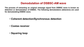
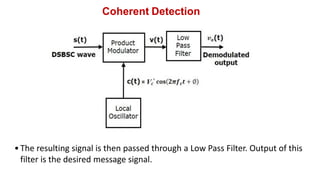
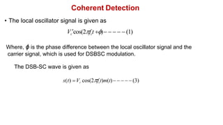
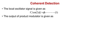
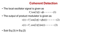
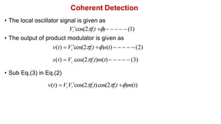
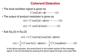
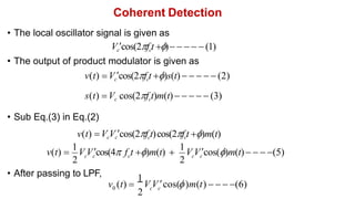
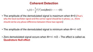
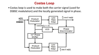
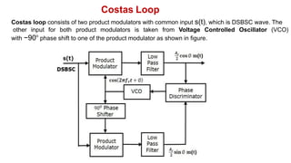
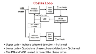
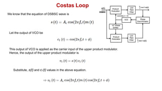
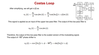
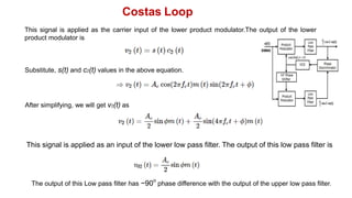
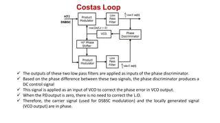
The document discusses different methods for demodulating DSBSC waves, including coherent detection, Costas loop, and squaring loop. Coherent detection extracts the message signal by multiplying the DSBSC wave with a local oscillator signal that is coherent in frequency and phase with the carrier. Costas loop is used to maintain phase coherence between the local oscillator and carrier. Squaring loop recovers the carrier signal by filtering the output of a squaring circuit to extract the signal at twice the carrier frequency.


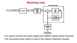
![Squaring Loop
• The output of the squarer is
y(t) s2
(t) [A cos(2 f t)m(t)]2
c c](https://image.slidesharecdn.com/5dsb-sc-demodulation-230528183543-e13959a5/85/5-DSB-SC-Demodulation-pdf-20-320.jpg)
![Squaring Loop
• The output of the squarer is
y(t) s2
(t) [A cos(2 f t)m(t)]2
c c
c
A2
c cos2
(2 f t)m2
(t)](https://image.slidesharecdn.com/5dsb-sc-demodulation-230528183543-e13959a5/85/5-DSB-SC-Demodulation-pdf-21-320.jpg)
![Squaring Loop
• The output of squarer is given the narrow band filter which is centered at
+/- 4πfc
• The output of filter is
• The output of the squarer is
y(t) s2
(t) [A cos(2 f t)m(t)]2
c c
c
A2
c cos2
(2 f t)m2
(t)
2
2
c
f t)]
m (t)[1 cos(4
2
A c](https://image.slidesharecdn.com/5dsb-sc-demodulation-230528183543-e13959a5/85/5-DSB-SC-Demodulation-pdf-22-320.jpg)
![Squaring Loop
• The output of squarer is given the narrow band filter which is centered at
+/- 4πfc
• The output of filter is
• The output of filter is given to PLL to provide constant frequency signal
cos(4πfct)
• Any drift in frequency is corrected by the error signal e(t) generated by LPF
• The output of VCO is connected to frequency divider(/2) to get cos(2πfct)
• The output of the squarer is
y(t) s2
(t) [A cos(2 f t)m(t)]2
c c
c
A2
c cos2
(2 f t)m2
(t)
2
2
c
f t)]
m (t)[1 cos(4
2
A c
2
2
c
A 2
c
f t)
v(t) m (t)cos(4](https://image.slidesharecdn.com/5dsb-sc-demodulation-230528183543-e13959a5/85/5-DSB-SC-Demodulation-pdf-23-320.jpg)