Downloaded 282 times

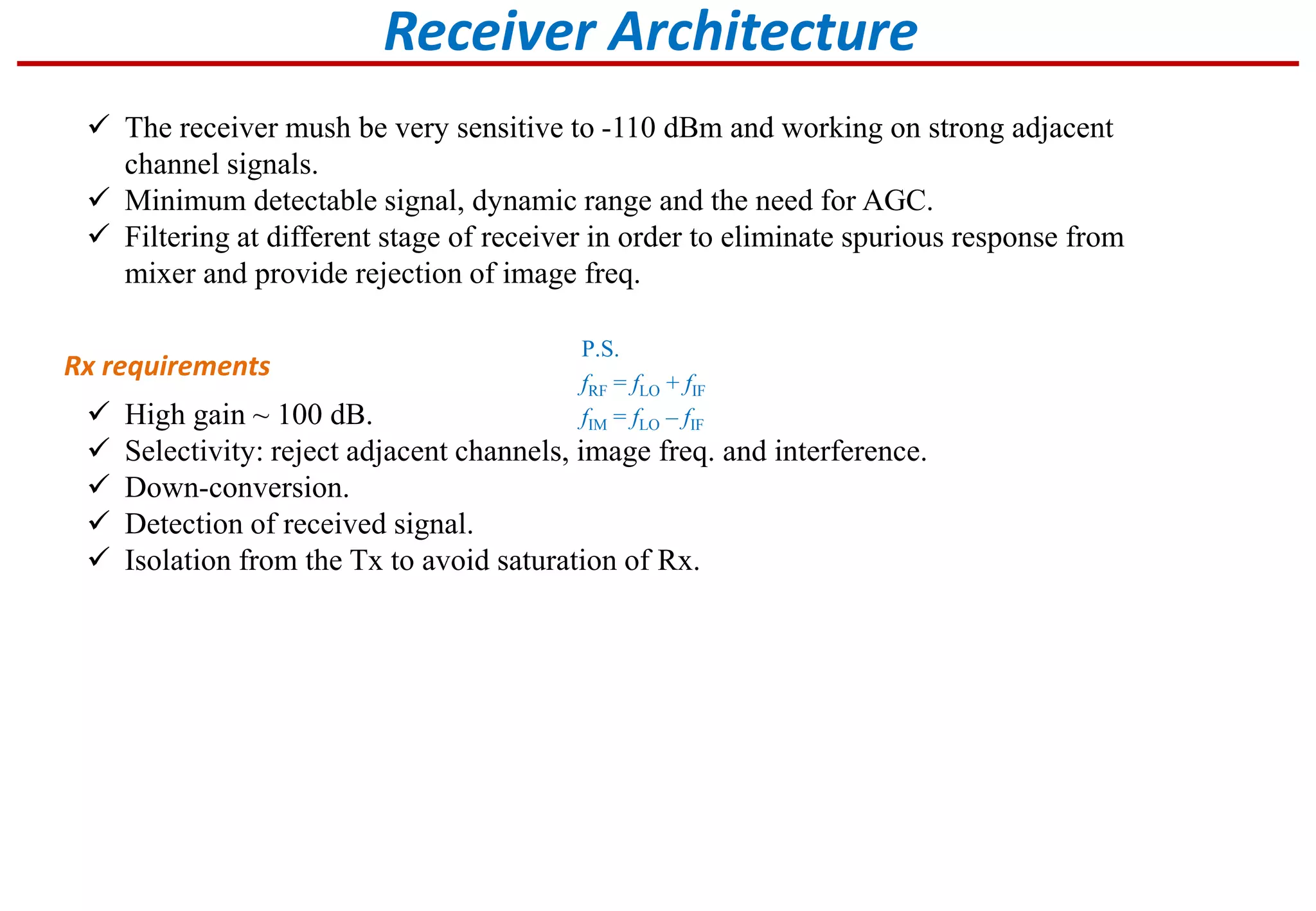


The document discusses receiver architecture and design requirements. It covers: 1. The receiver must provide high gain of 100dB while spread across RF, IF, and baseband stages to avoid instability. It must also be sensitive to weak signals down to -110dBm and reject strong adjacent channels. 2. A superheterodyne receiver is most common as it allows for sharper filters at IF to improve selectivity. Downconverting to IF also eases image filtering requirements. 3. Automatic gain control is needed to adjust the receiver gain over a wide range of input signal levels and fit them into the baseband processing range. It helps prevent compression from strong signals exceeding the 1dB compression point.
Introduction to receiver design, focusing on architecture and key components.
Discusses receiver sensitivity, gain, selectivity, dynamic range, and down-conversion.
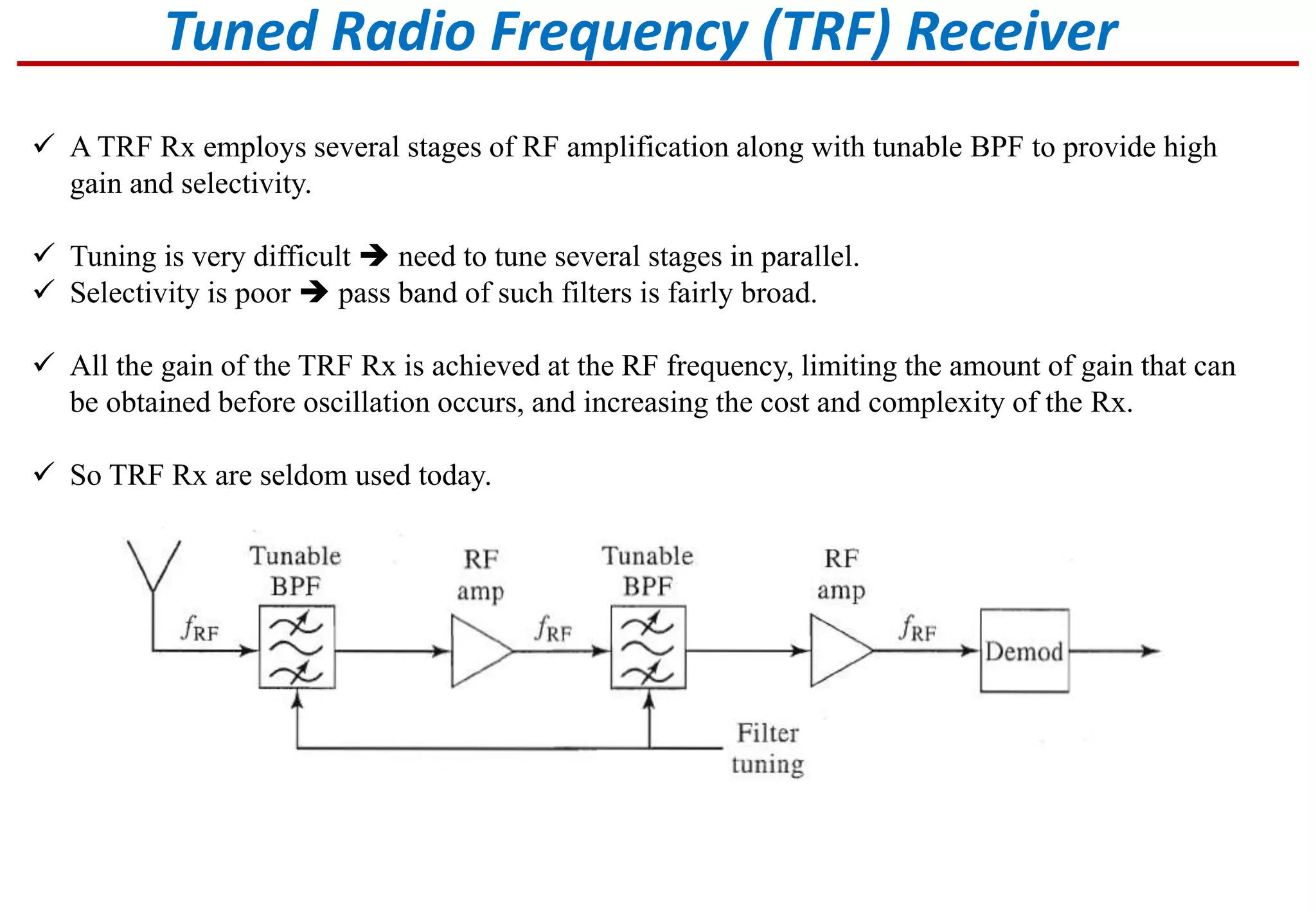
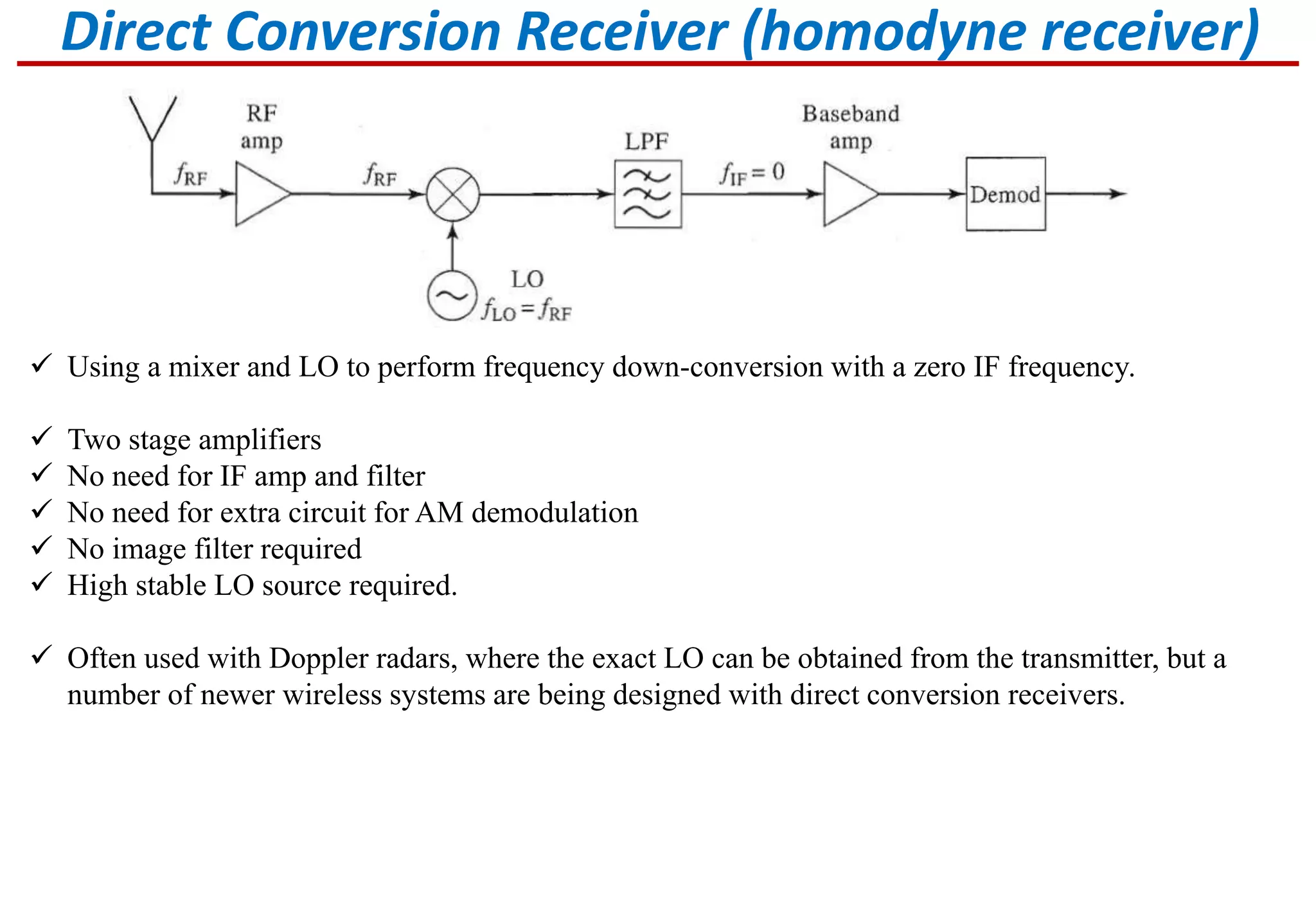
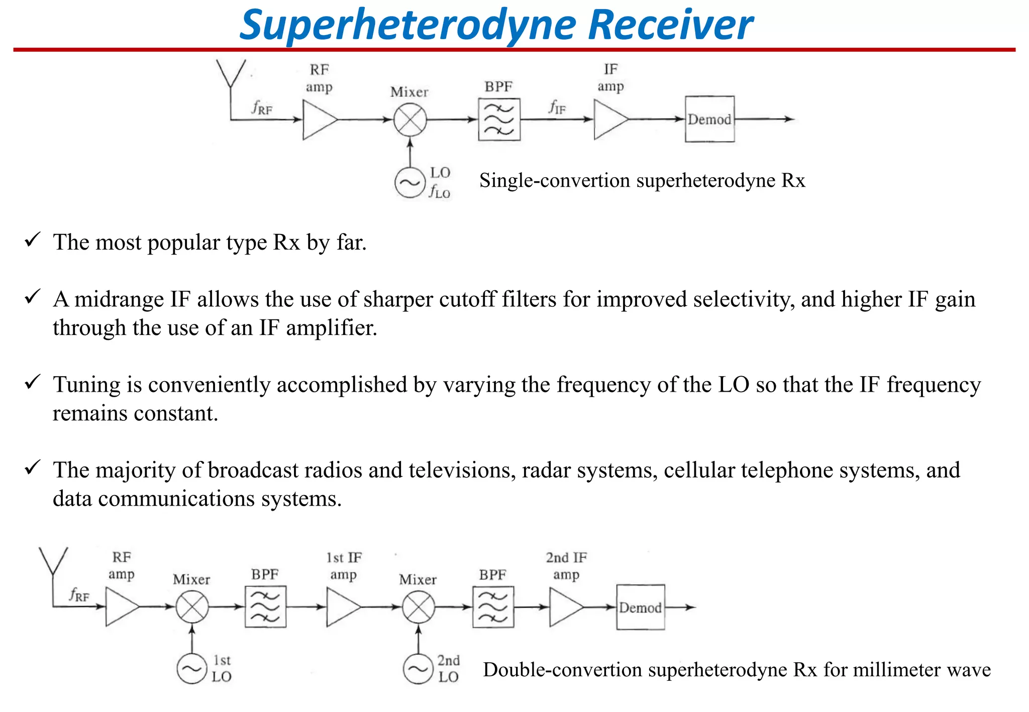
Explains TRF, Direct Conversion, and Superheterodyne receivers, highlighting advantages and limitations.
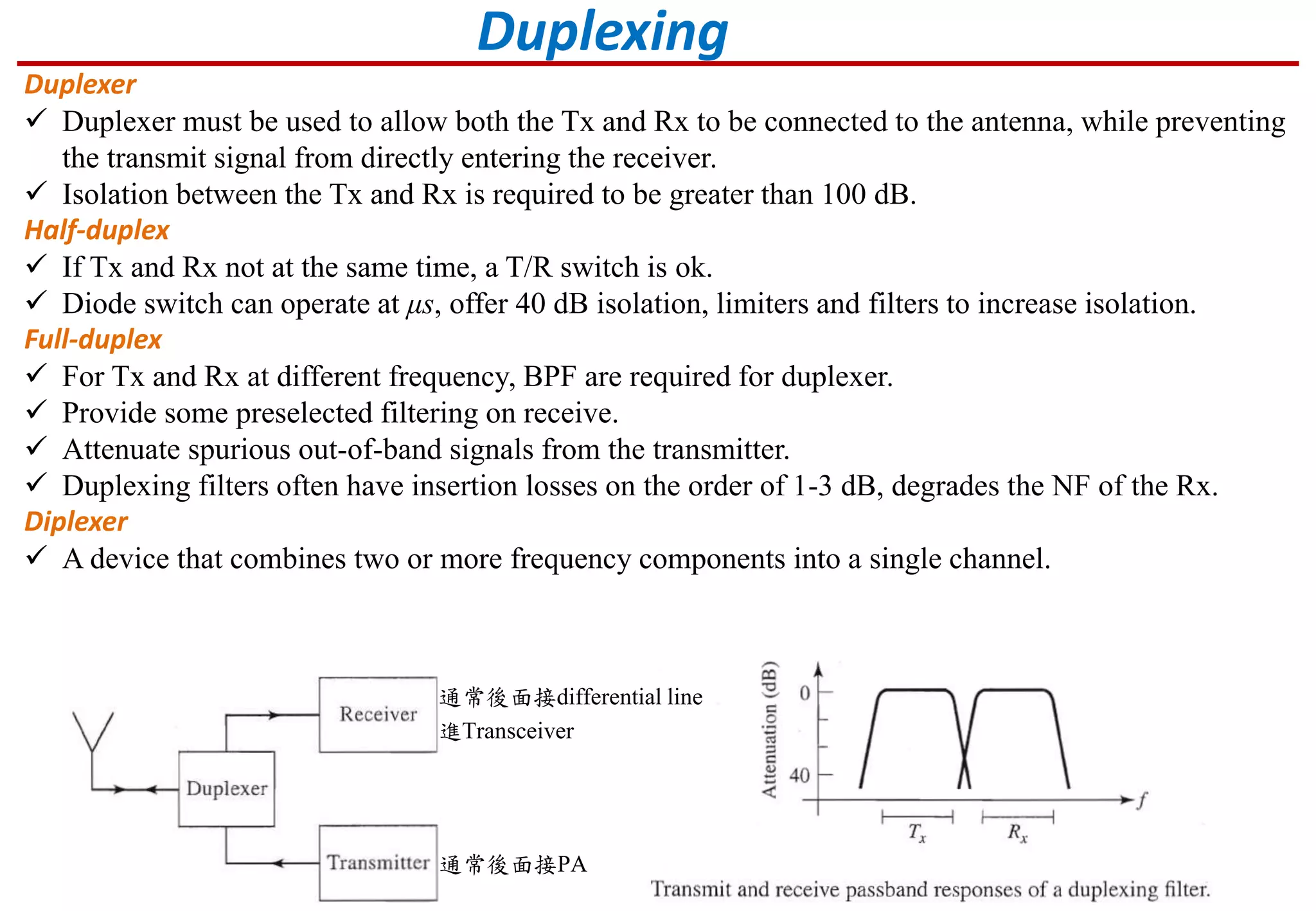
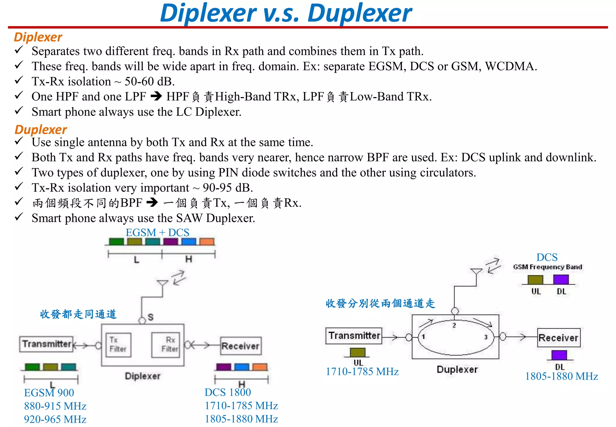
Describes duplexer and diplexer functionalities for simultaneous Tx and Rx, including isolation requirements.
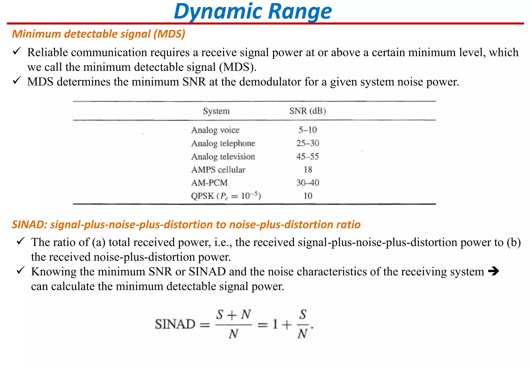
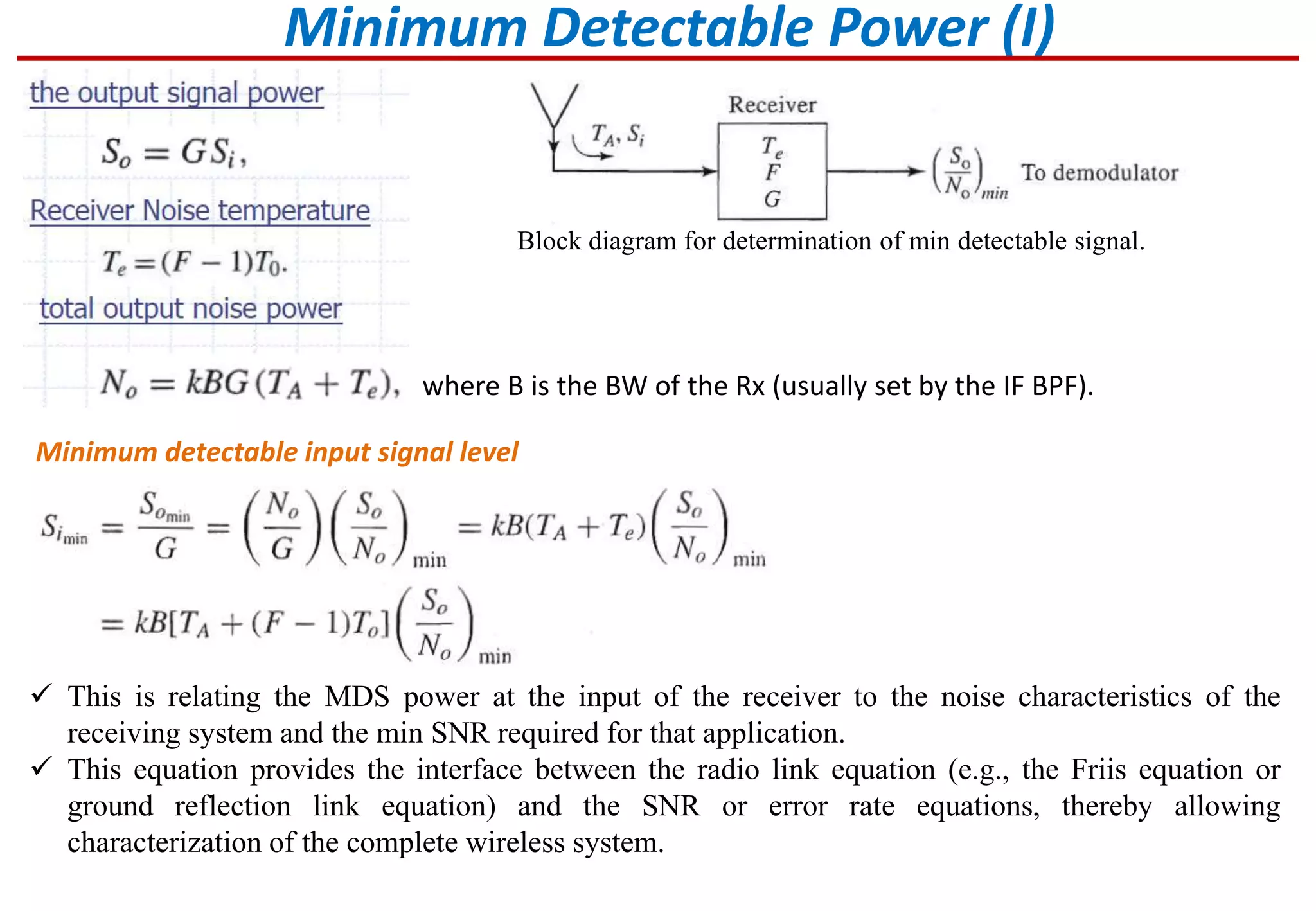
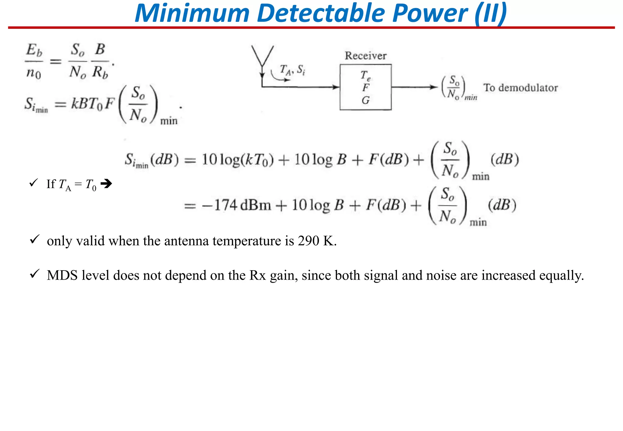
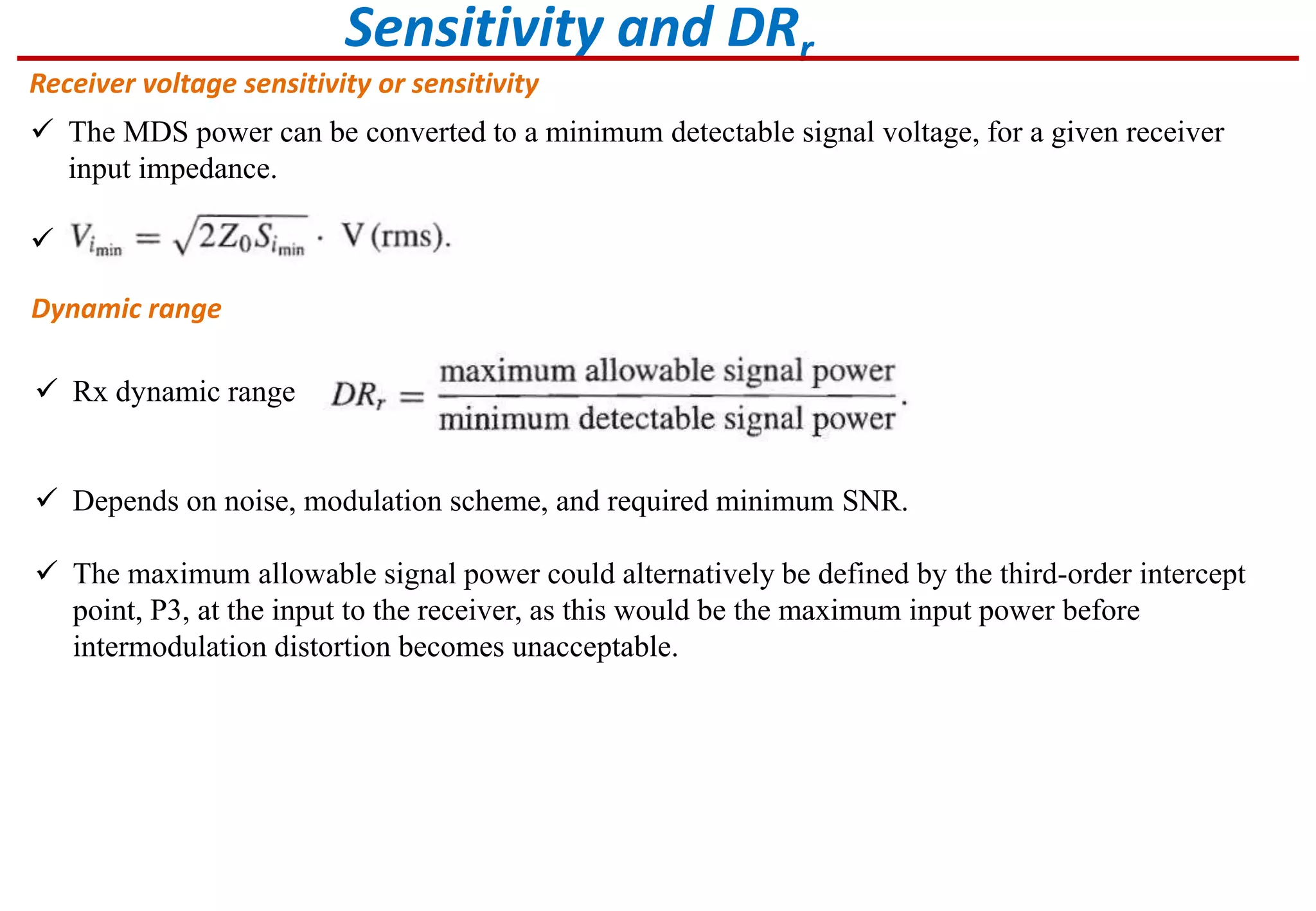
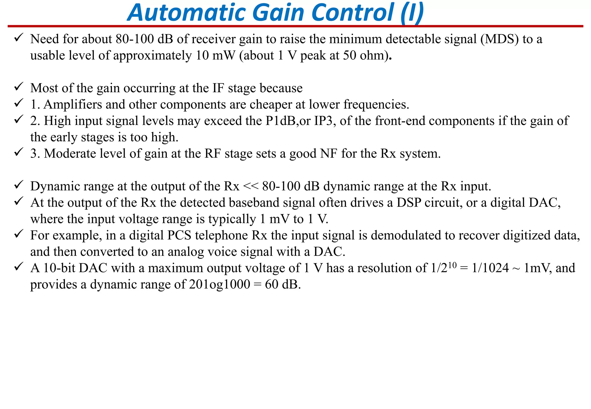
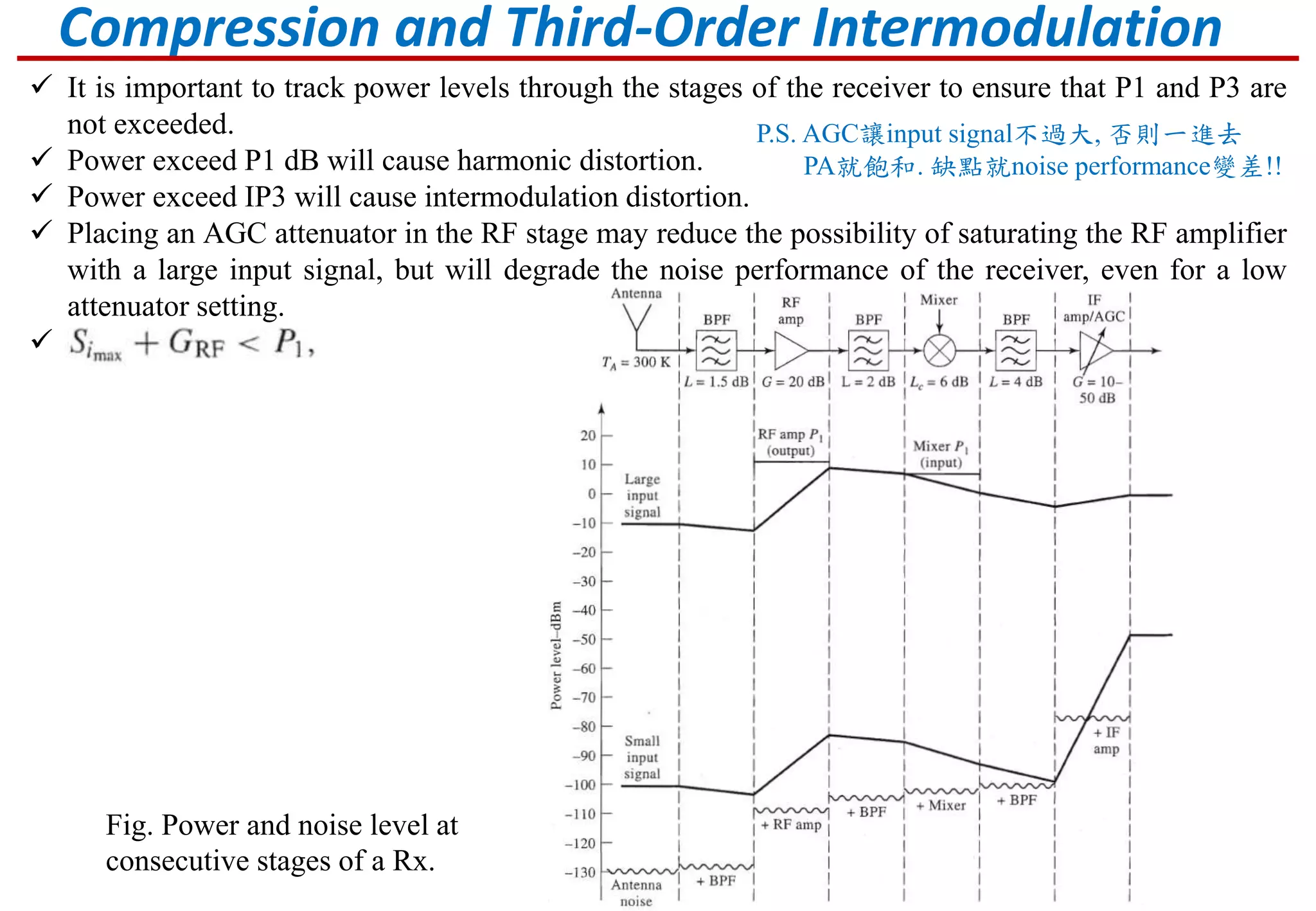
Focus on MDS concept, calculation of signal levels, sensitivity, and methods to manage receiver dynamic range.Explains AGC role in adjusting receiver gain based on input signal strength to enhance performance.
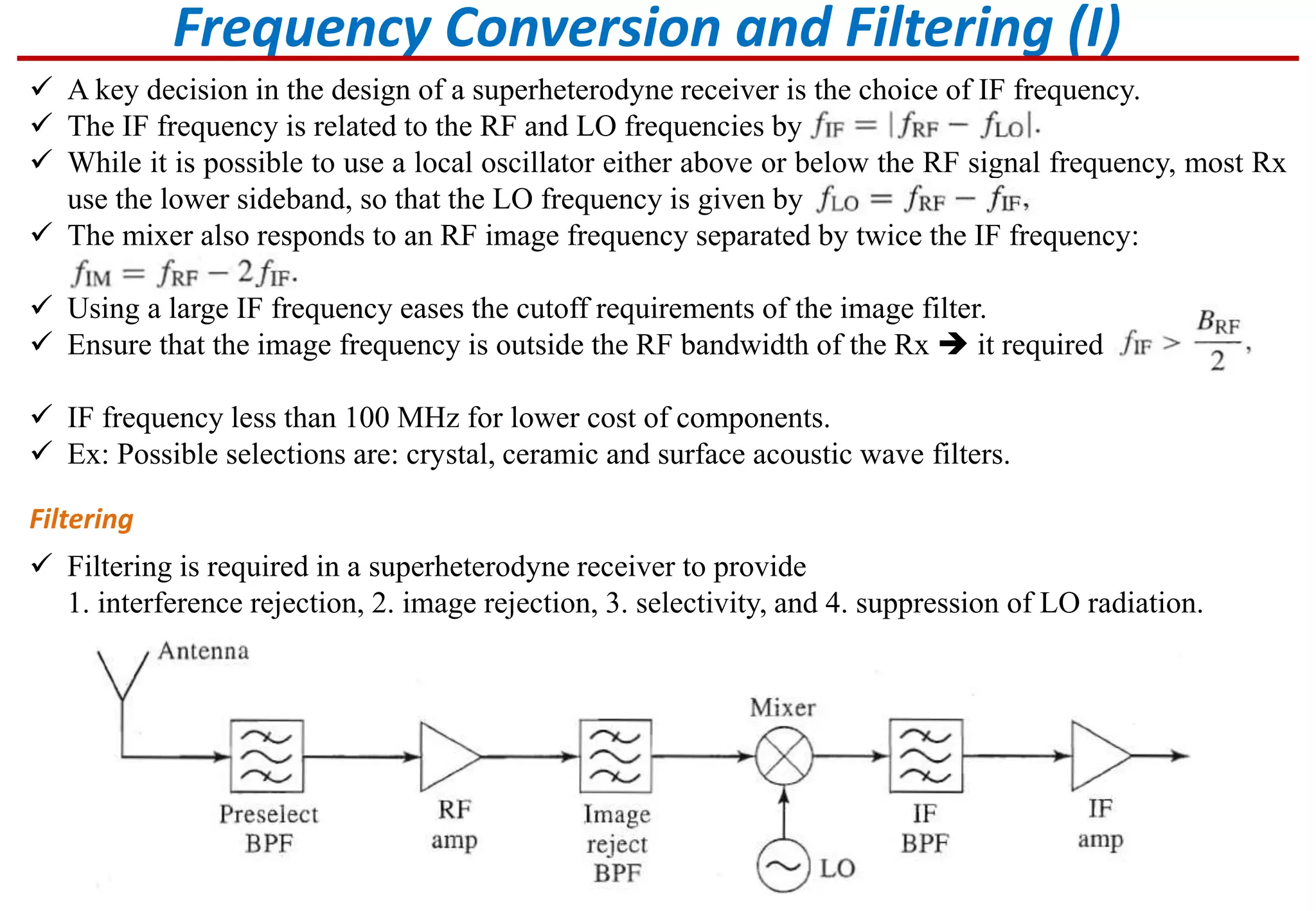
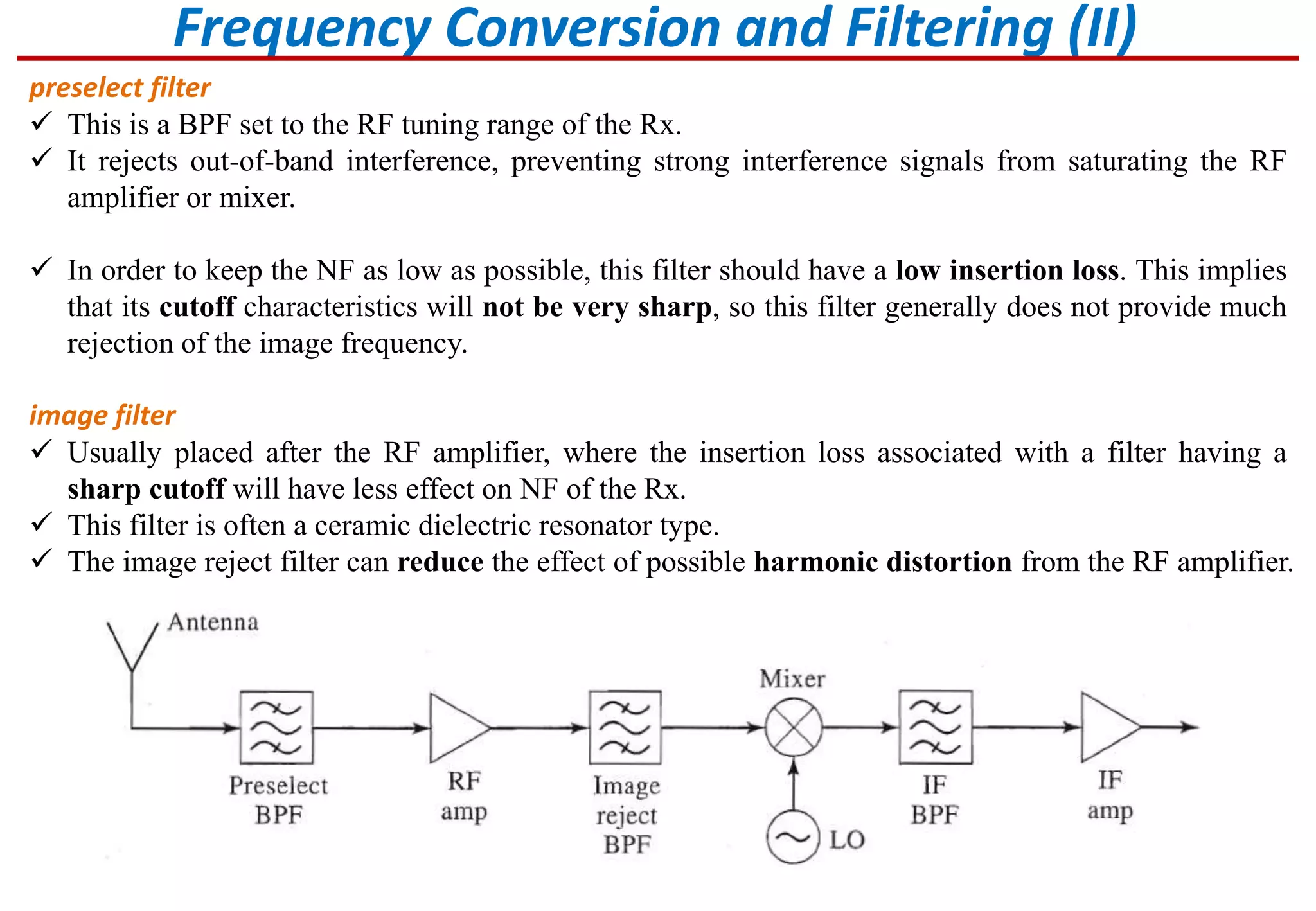
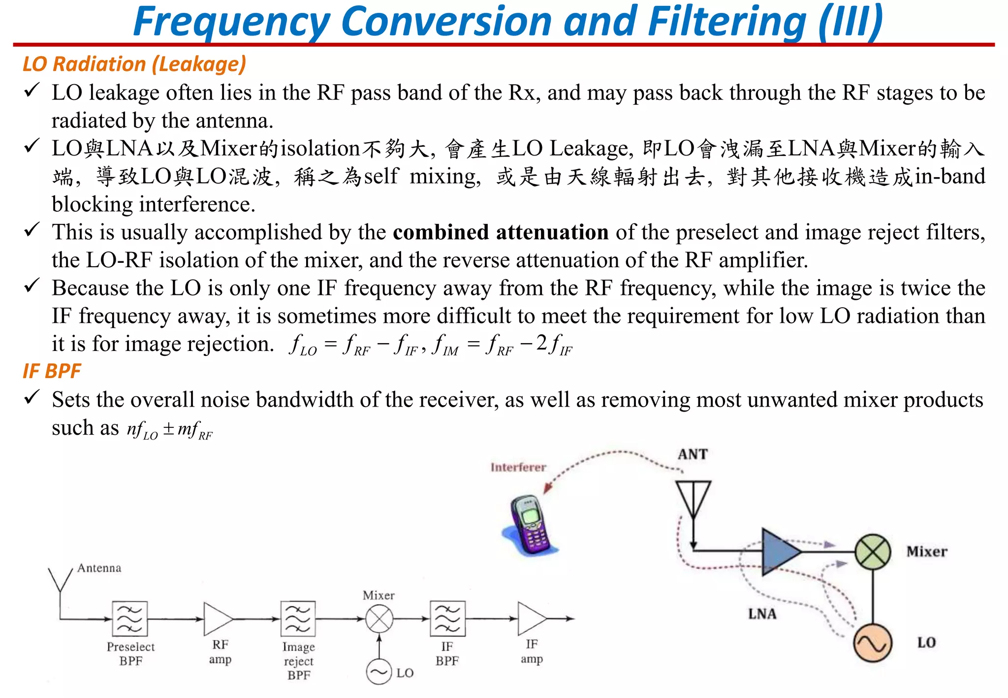
Details on IF frequency selection, filtering processes, and challenges with LO leakage and spurious responses.
Illustrates real-world applications of receiver designs.