Downloaded 1,366 times
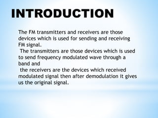
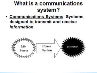

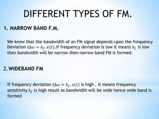
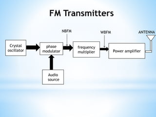
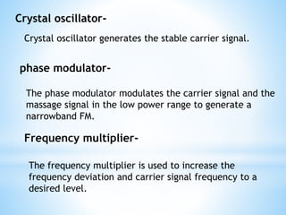
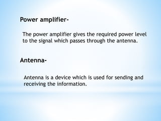
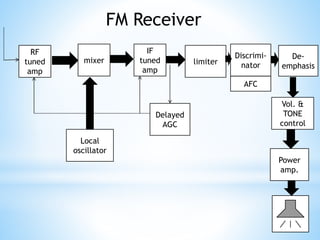
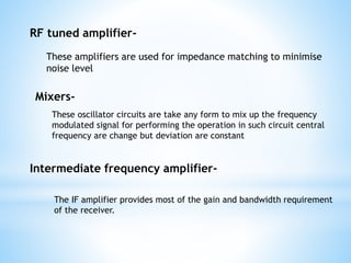
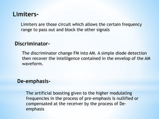
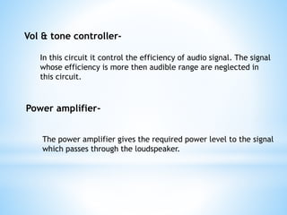

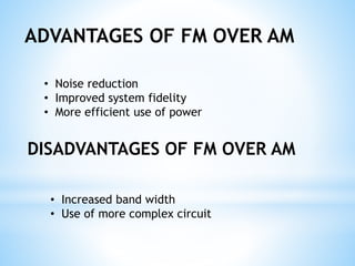
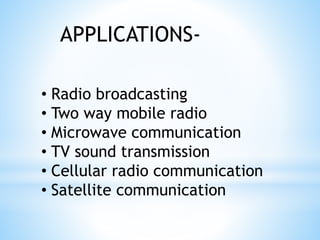


FM transmitters and receivers are used for sending and receiving FM signals. Transmitters modulate a carrier wave with an audio signal to generate an FM signal, which is transmitted through a band. Receivers receive the modulated signal, demodulate it to extract the original audio signal. FM offers advantages over AM like noise reduction, improved fidelity, and more efficient power use, though it requires more complex circuits and a larger bandwidth. Applications of FM include radio broadcasting, mobile radio, TV sound, and cellular/satellite communication.


![谷歌留痕技术 [ 𝙩𝙤𝙥 𝟮𝟯𝟯. 𝙘 𝙤𝙢 ]](https://cdn.slidesharecdn.com/ss_thumbnails/top233-260130174328-3833018c-thumbnail.jpg?width=640&height=640&fit=bounds)


