Downloaded 314 times
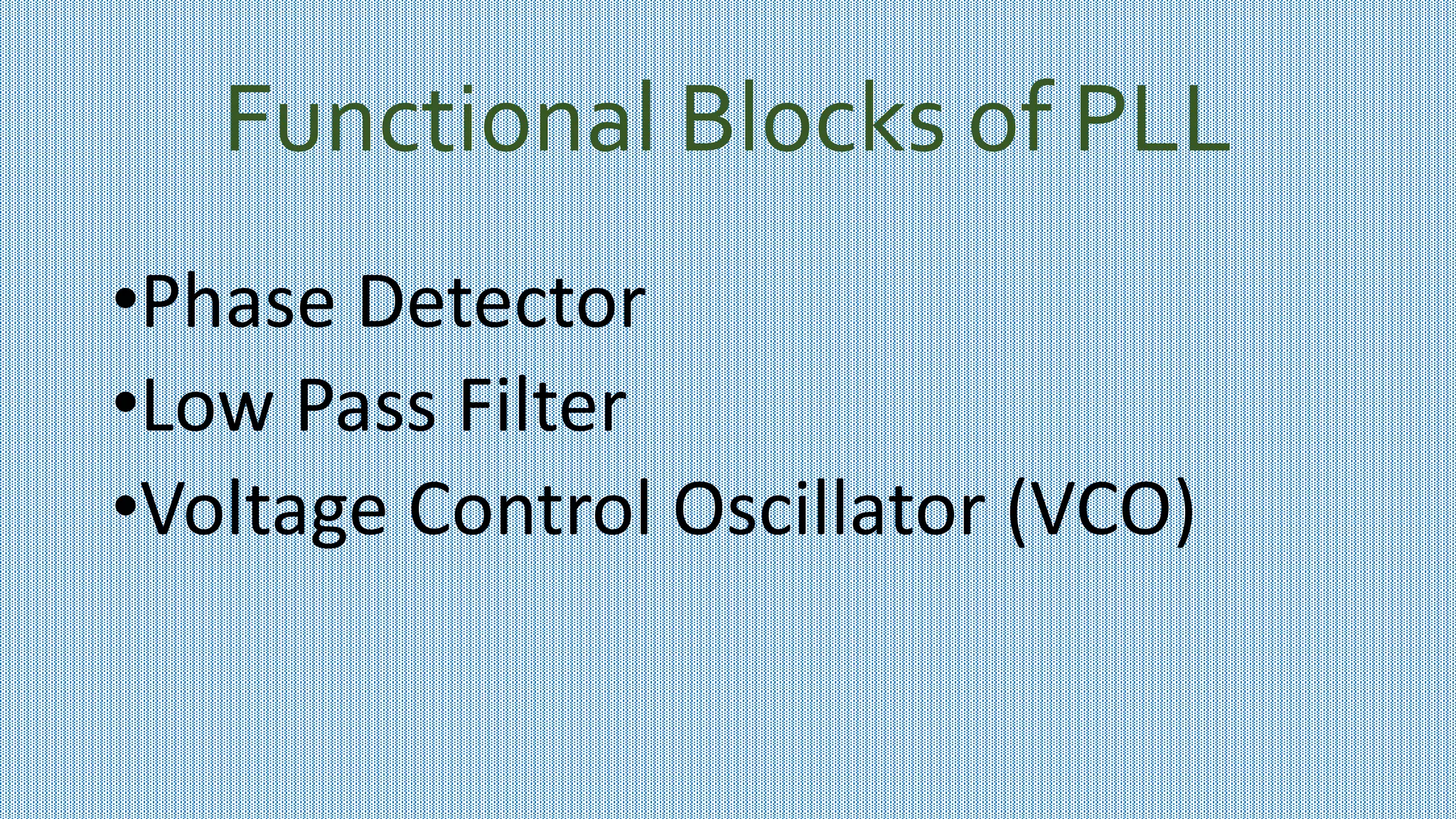
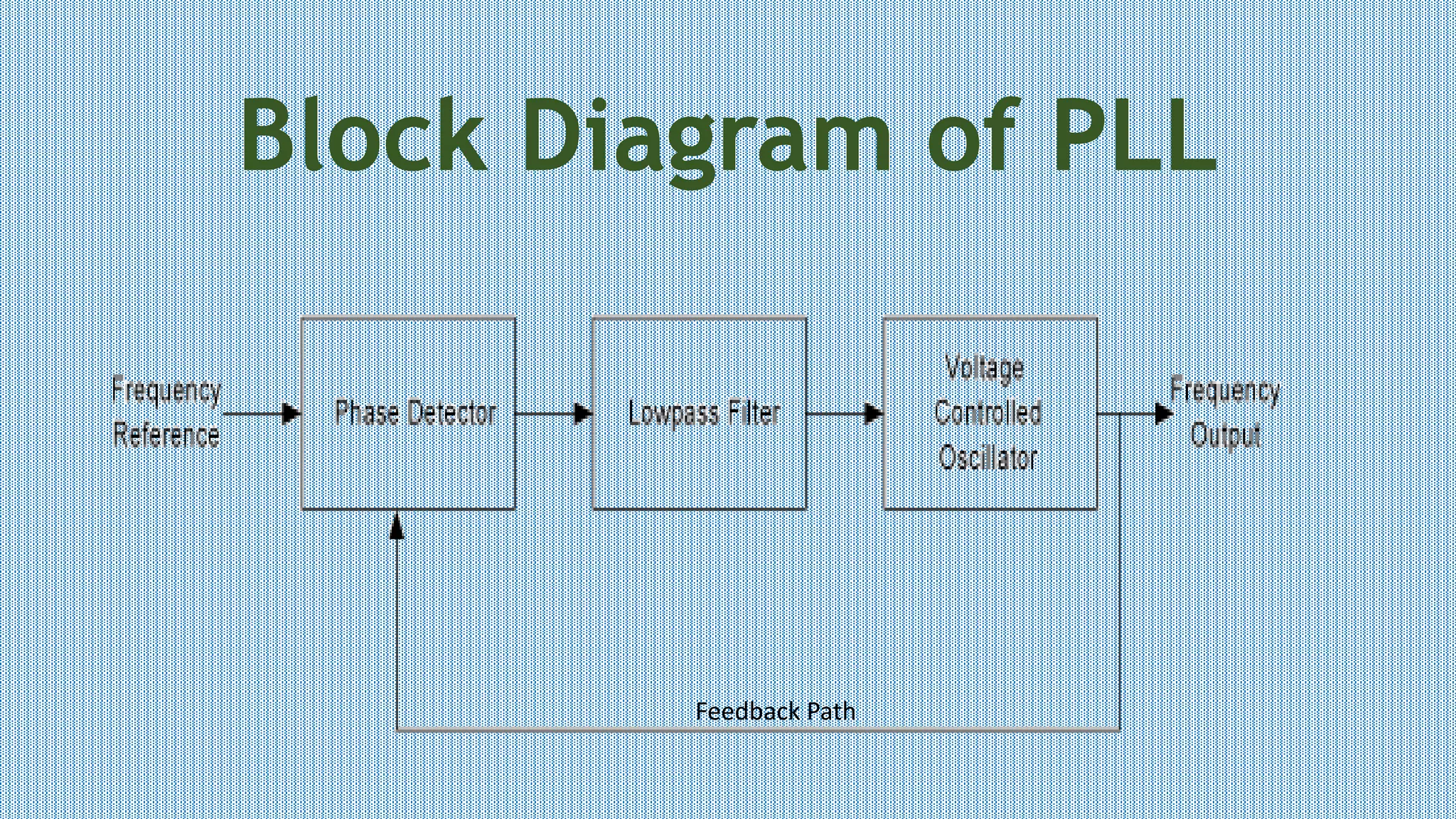


The document discusses a Phase Locked Loop (PLL). It describes PLL as a circuit that synchronizes an output signal generated by an oscillator to match the frequency and phase of a reference input signal. The key functional blocks of a PLL are a phase detector, low pass filter, and voltage controlled oscillator (VCO). The phase detector compares the input and feedback frequencies and provides an error signal. The low pass filter removes noise and the VCO generates the output frequency controlled by the error signal voltage. A PLL goes through free running, capture, and phase locked stages of operation. Applications of PLL include frequency modulation/demodulation and signal synchronization.