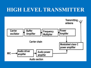
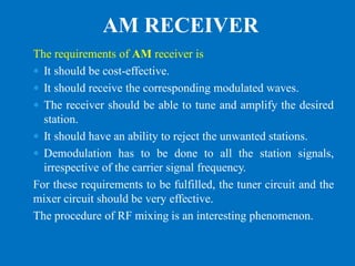
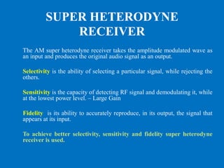
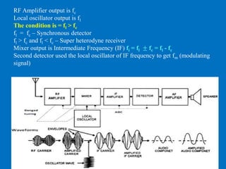
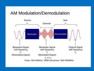
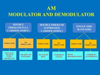
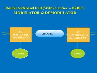
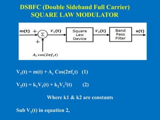
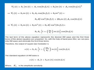
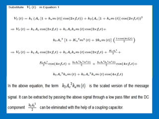
This document discusses various aspects of amplitude modulation (AM) including modulation, demodulation, and different types of AM modulators and demodulators. It describes how AM works by varying the amplitude of the carrier wave proportionally to the message signal. It also explains amplitude demodulation, the process of extracting the original message signal. Finally, it covers different AM systems like DSB-FC, DSB-SC, SSB and their corresponding modulators and demodulators like square law, balanced, and coherent detectors.
![SQUARE LAW - DEMODULATOR
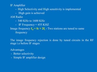
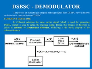
The process of extracting an original message signal from the modulated
wave is known as detection or demodulation. The circuit, which demodulates the
modulated wave is known as the demodulator
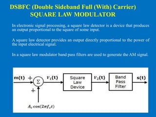
The Standard form of AM wave is
V1(t) = Ac[1+kam(t)]Cos(2πfct)
V2(t) = k1V1(t)+k2V1
2(t) (1)
Where, V1(t) is the input of the square law device, which is nothing but the
AM wave
V2(t) is the output of the square law device
k1 and k2 are constants](https://image.slidesharecdn.com/am-modulatoranddemodulator-200726100747/85/AM-Modulator-and-Demodulator-10-320.jpg)
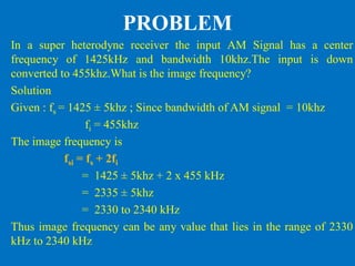
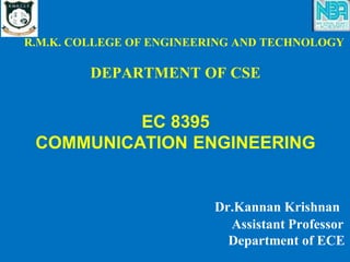
![BALANCED MODULATOR
Balanced Modulator consists of two identical AM modulators.
These two modulators are arranged in a balanced configuration in
order to suppress the carrier signal. Hence, it is called as Balanced
modulator.
Double Side Band Suppressed
Carrier (DSBSC) - MODULATOR
The same carrier signal
C(t) = Ac Cos (2πfct) is applied as one of
the inputs to these two AM modulators.
Output of the upper AM modulator is
S1(t) = Ac[1+kam(t)]Cos(2πfct)
Output of the lower AM modulator is
S2(t) = Ac[1−kam(t)]Cos(2πfct)](https://image.slidesharecdn.com/am-modulatoranddemodulator-200726100747/85/AM-Modulator-and-Demodulator-12-320.jpg)
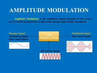
![s1(t) with positive sign and s2(t) with negative sign are applied as inputs to
summer block.
Thus, the summer block produces an output s(t) which is the difference of s1(t)
and s2(t).
s(t) = Ac[1+kam(t)]cos(2πfct) − Ac [1−kam(t)]cos(2πfct)
s(t) = Accos(2πfct)+ Ac kam(t)cos(2πfct)− Ac cos(2πfct)+ Ac kam(t)cos(2πfct)
s(t) = 2 Ac ka m(t)cos(2πfct)
We know the standard equation of DSBSC wave is
S(t)= Ac m(t)cos(2πfct)
By comparing the output of summer block with the standard equation of
DSBSC wave, we will get the scaling factor as 2ka](https://image.slidesharecdn.com/am-modulatoranddemodulator-200726100747/85/AM-Modulator-and-Demodulator-13-320.jpg)
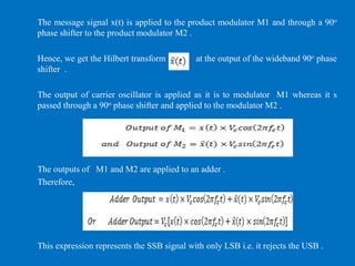
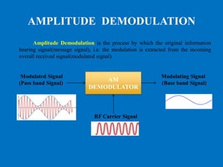
![Let the DSBSC wave be s(t) = Ac Cos(2πfct) m(t)
The output of the local oscillator is c(t) = Ac Cos(2πfct+ϕ)
From the figure, Output of product modulator as v(t) = s(t) c(t)
v(t) = Ac Cos(2πfct) m(t) Ac Cos(2πfct + ϕ)
= Ac2 Cos(2πfct) Cos (2πfct + ϕ) m(t)
= Ac2 /2[Cos(4πfct + ϕ) + Cosϕ ]m(t)
v(t) = Ac2 /2 Cosϕm(t) + Ac2/2Cos (4πfct + ϕ)m(t)
Here the first term is the scaled version of the message signal. It can be extracted by
passing the above signal through a low pass filter.
Therefore, the output of low pass filter is V0t = Ac2 /2Cosϕm(t)
The demodulated signal amplitude will be maximum, when ϕ = 00
That’s why the local oscillator signal and the carrier signal should be in phase, i.e.,
there should not be any phase difference between these two signals.](https://image.slidesharecdn.com/am-modulatoranddemodulator-200726100747/85/AM-Modulator-and-Demodulator-15-320.jpg)
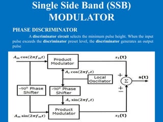
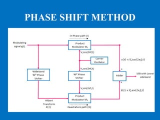
![The modulating signal = Am cos (2πfmt)
The carrier signal = Ac cos (2πfct)
The output of upper product modulator is
S1(t) = Am cos (2πfmt) Ac cos (2πfct)
= Am Ac /2{cos[2π(fc+fm)t]+cos[2π(fc−fm)t]}
The output of lower product modulator is
S2(t) = Am Ac cos(2πfmt −900)cos(2πfct −900)
= Am Ac sin(2πfmt)sin(2πfct)
= Am Ac/ 2{cos[2π(fc−fm)t] − cos[2𝜋(fc+fm)t]}
At the Summer S(t) = S1(t) + S2(t)](https://image.slidesharecdn.com/am-modulatoranddemodulator-200726100747/85/AM-Modulator-and-Demodulator-17-320.jpg)
![S(t) = Am Ac /2{cos[2π(fc+fm)t]+cos[2π(fc−fm)t]} +
Am Ac/ 2{cos[2π(fc−fm)t] − cos[2𝜋(fc+fm)t]}
S(t) = Am Ac cos2π(fc−fm)t
Subtract S2(t) from S1(t) to get S(t)
S(t) = Am Ac /2{cos[2π(fc+fm)t]+cos[2π(fc−fm)t]} -
Am Ac/ 2{cos[2π(fc−fm)t] − cos[2𝜋(fc+fm)t]}
S(t) = Am Ac cos2π(fc+fm)t
Hence, by properly choosing the polarities of inputs at
summer block, we will get SSBSC wave having a upper
sideband or a lower sideband.](https://image.slidesharecdn.com/am-modulatoranddemodulator-200726100747/85/AM-Modulator-and-Demodulator-18-320.jpg)
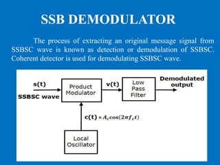
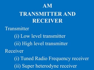
![Consider the following SSBSC wave having a LOWER SIDEBAND
S(t) = Am Ac / 2 Cos[2π(fc−fm)t]
The output of the local oscillator is
C(t) = Ac Cos(2πfct)
From the figure, we can write the output of product modulator as v(t) = s(t)c(t)
v(t) = Am Ac /2 Cos[2π(fc−fm)t] AcCos(2πfct)
= Am Ac
2 /2 Cos[2π(fc−fm)t] Cos(2πfct)
= Am Ac
2 /4{Cos2π(2fc−fm)t + Cos(2πfm)t}
In the above equation, the Second term is the scaled version of the message
signal. It can be extracted by passing the above signal through a low pass filter.
The output of low pass filter is
V0(t)=Am Ac
2 /4 Cos(2πfmt)
Here, the scaling factor is Ac2/4](https://image.slidesharecdn.com/am-modulatoranddemodulator-200726100747/85/AM-Modulator-and-Demodulator-20-320.jpg)