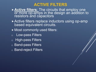
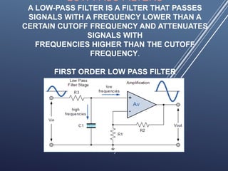
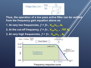
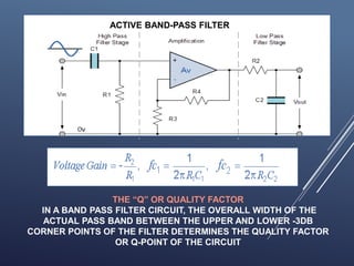
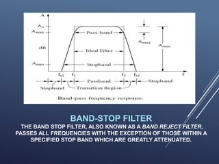
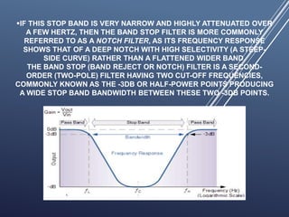
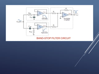
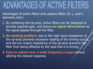
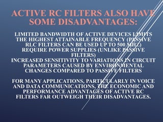
This presentation discusses active filters, which use operational amplifiers in addition to resistors and capacitors. It describes the basic types of filters - low pass, high pass, band pass and band stop. Low pass filters pass low frequencies and attenuate high frequencies above the cutoff frequency. High pass filters do the opposite, passing high frequencies and attenuating low frequencies below the cutoff. Band pass filters pass a range of frequencies between an upper and lower cutoff, while band stop filters attenuate a range of frequencies like a notch filter. Active filters have advantages over passive filters like independent gain control and no loading effects.
Study of vco_Voltage controlled OscillatorNeha Mannewar
Voltage controlled Oscillator,Voltage controlled oscillator is a type of oscillator where the frequency of the output oscillations can be varied by varying the amplitude of an input voltage signal.Voltage controlled oscillators are commonly used in frequency (FM), pulse (PM) modulators and phase locked loops (PLL). Another application of the voltage controlled oscillator is the variable frequency signal generator itself.
Details: https://electronicsembeddedworld.blogspot.com/2018/06/performance-management-mcq.html
FM demodulation involves changing the frequency variations in a signal into amplitude variations at baseband, e.g. audio. There are several techniques and circuits that can be used each with its own advantages and disadvantages.
In any radio that is designed to receive frequency modulated signals there is some form of FM demodulator or detector. This circuit takes in frequency modulated RF signals and takes the modulation from the signal to output only the modulation that had been applied at the transmitter.
There are several types of FM detector / demodulator that can be used. Some types were more popular in the days when radios were made from discrete devices, but nowadays the PLL based detector and quadrature / coincidence detectors are the most widely used as they lend themselves to being incorporated into integrated circuits very easily...
A wave analyzer is an instrument designed to measure relative amplitudes of single frequency components in a complex waveform. Basically, a wave instrument acts as a frequency selective voltmeter which is tuned to the frequency of one signal while rejecting all other signal components.
Band pass filter is defined in informative way so any one get knowledge from it and its basics also the multisim simulation circuit is present in slides if any one want then he/she will contact through mail or linkedin account.
RF Carrier oscillator
To generate the carrier signal.
Usually a crystal-controlled oscillator is used.
Buffer amplifier
Low gain, high input impedance linear amplifier.
To isolate the oscillator from the high power amplifiers.
Modulator : can use either emitter collector modulation
Intermediate and final power amplifiers (pull-push modulators)
Required with low-level transmitters to maintain symmetry in the AM envelope
Coupling network
Matches output impedance of the final amplifier to the transmission line/antenn
Applications are in low-power, low-capacity systems : wireless intercoms, remote control units, pagers and short-range walkie-talkie
Modulating signal is processed similarly as in low-level transmitter except for the addition of power amplifier
Power amplifier
To provide higher power modulating signal necessary to achieve 100% modulation (carrier power is maximum at the high-level modulation point).
Same circuit as low-level transmitter for carrier oscillator, buffer and driver but with addition of power amplifier
Active filters are type of filters which use the operational amplifier ics for their operation and in this slides any one can get more information in little bit of time. so i recommended if any one want to study filters then must read it.
In this presentation we discuss about the active filters and mentioned its frequency response along with block diagrams. Also discussed its pros and cons in this presentation.
Some important Referencing Style used in researchmainly four type referencing styles are explained in this presentation. Chicago, MLA, APA,and AIP. In-text citation and refrencing style both are explained here with the help of format and by giving examples.
Observation of Io’s Resurfacing via Plume Deposition Using Ground-based Adapt...Sérgio Sacani
Since volcanic activity was first discovered on Io from Voyager images in 1979, changes
on Io’s surface have been monitored from both spacecraft and ground-based telescopes.
Here, we present the highest spatial resolution images of Io ever obtained from a groundbased telescope. These images, acquired by the SHARK-VIS instrument on the Large
Binocular Telescope, show evidence of a major resurfacing event on Io’s trailing hemisphere. When compared to the most recent spacecraft images, the SHARK-VIS images
show that a plume deposit from a powerful eruption at Pillan Patera has covered part
of the long-lived Pele plume deposit. Although this type of resurfacing event may be common on Io, few have been detected due to the rarity of spacecraft visits and the previously low spatial resolution available from Earth-based telescopes. The SHARK-VIS instrument ushers in a new era of high resolution imaging of Io’s surface using adaptive
optics at visible wavelengths.
Seminar of U.V. Spectroscopy by SAMIR PANDASAMIR PANDA
Spectroscopy is a branch of science dealing the study of interaction of electromagnetic radiation with matter.
Ultraviolet-visible spectroscopy refers to absorption spectroscopy or reflect spectroscopy in the UV-VIS spectral region.
Ultraviolet-visible spectroscopy is an analytical method that can measure the amount of light received by the analyte.
Earliest Galaxies in the JADES Origins Field: Luminosity Function and Cosmic ...Sérgio Sacani
We characterize the earliest galaxy population in the JADES Origins Field (JOF), the deepest
imaging field observed with JWST. We make use of the ancillary Hubble optical images (5 filters
spanning 0.4−0.9µm) and novel JWST images with 14 filters spanning 0.8−5µm, including 7 mediumband filters, and reaching total exposure times of up to 46 hours per filter. We combine all our data
at > 2.3µm to construct an ultradeep image, reaching as deep as ≈ 31.4 AB mag in the stack and
30.3-31.0 AB mag (5σ, r = 0.1” circular aperture) in individual filters. We measure photometric
redshifts and use robust selection criteria to identify a sample of eight galaxy candidates at redshifts
z = 11.5 − 15. These objects show compact half-light radii of R1/2 ∼ 50 − 200pc, stellar masses of
M⋆ ∼ 107−108M⊙, and star-formation rates of SFR ∼ 0.1−1 M⊙ yr−1
. Our search finds no candidates
at 15 < z < 20, placing upper limits at these redshifts. We develop a forward modeling approach to
infer the properties of the evolving luminosity function without binning in redshift or luminosity that
marginalizes over the photometric redshift uncertainty of our candidate galaxies and incorporates the
impact of non-detections. We find a z = 12 luminosity function in good agreement with prior results,
and that the luminosity function normalization and UV luminosity density decline by a factor of ∼ 2.5
from z = 12 to z = 14. We discuss the possible implications of our results in the context of theoretical
models for evolution of the dark matter halo mass function.
(May 29th, 2024) Advancements in Intravital Microscopy- Insights for Preclini...Scintica Instrumentation
Intravital microscopy (IVM) is a powerful tool utilized to study cellular behavior over time and space in vivo. Much of our understanding of cell biology has been accomplished using various in vitro and ex vivo methods; however, these studies do not necessarily reflect the natural dynamics of biological processes. Unlike traditional cell culture or fixed tissue imaging, IVM allows for the ultra-fast high-resolution imaging of cellular processes over time and space and were studied in its natural environment. Real-time visualization of biological processes in the context of an intact organism helps maintain physiological relevance and provide insights into the progression of disease, response to treatments or developmental processes.
In this webinar we give an overview of advanced applications of the IVM system in preclinical research. IVIM technology is a provider of all-in-one intravital microscopy systems and solutions optimized for in vivo imaging of live animal models at sub-micron resolution. The system’s unique features and user-friendly software enables researchers to probe fast dynamic biological processes such as immune cell tracking, cell-cell interaction as well as vascularization and tumor metastasis with exceptional detail. This webinar will also give an overview of IVM being utilized in drug development, offering a view into the intricate interaction between drugs/nanoparticles and tissues in vivo and allows for the evaluation of therapeutic intervention in a variety of tissues and organs. This interdisciplinary collaboration continues to drive the advancements of novel therapeutic strategies.
2. INTRODUCTION
Filters are circuits that are capable of passing
signals within a band of frequencies while rejecting
or blocking signals of frequencies outside this
band.
This property of filters is also called “frequency
selectivity”.
3. TYPES OF FILTER
There are two broad categories of filters:
Analog or digital
Passive or active
Analog filters: designed to process
analog signals
Digital filters: process analog signals using
digital signals
4. Passive filters
Passive filters use resistors, capacitors, and
inductors (RLC networks).
To minimize distortion in the filter characteristic,
it is desirable to use inductors with high quality
factors
practical inductors includes a series resistance.
They are particularly non-ideal
They are bulky and expensive
5. ACTIVE FILTERS
Active filters: The circuits that employ one
or more op-amps in the design an addition to
resistors and capacitors
Active filters replace inductors using op-amp
based equivalent circuits.
Most commonly used filters:
o Low-pass Filters
o High-pass Filters
o Band-pass Filters
o Band-reject Filters
6. LOW PASS FILTERS
A LOW-PASS FILTER IS A FILTER THAT PASSES
SIGNALS WITH A FREQUENCY LOWER THAN A
CERTAIN CUTOFF FREQUENCY AND ATTENUATES
SIGNALS WITH
FREQUENCIES HIGHER THAN THE CUTOFF
FREQUENCY.
FIRST ORDER LOW PASS FILTER
7. Thus, the operation of a low pass active filter can be verified
from the frequency gain equation above as:
1. At very low frequencies, ƒ < ƒc , Vout/vin = Af
2. At the cut-off frequency, ƒ = ƒc , Vout/vin = .707 Af
3. At very high frequencies, ƒ > ƒc , Vout/vin < Af
v
Frequency response curve
8. APPLICATION OF ACTIVE LOW -PASS FILTER
ACTIVE LOW PASS FILTERS ARE IN AUDIO AMPLIFIERS, EQUALIZERS
OR SPEAKER SYSTEMS TO DIRECT THE LOWER FREQUENCY BASS
SIGNALS TO THE LARGER BASS SPEAKERS OR TO REDUCE ANY HIGH
FREQUENCY NOISE OR “HISS” TYPE DISTORTION. WHEN USED LIKE
THIS IN AUDIO APPLICATIONS THE ACTIVE LOW PASS FILTER IS
SOMETIMES CALLED A “BASS BOOST” FILTER.
HIGH-PASS FILTER
HIGH-PASS FILTER (HPF) ATTENUATES CONTENT BELOW A CUTOFF
FREQUENCY, ALLOWING HIGHER FREQUENCIES TO PASS THROUGH
THE FILTER.
9. FIRST ORDER HIGH-PASS FILTER
THE OPERATION OF A HIGH PASS ACTIVE FILTER CAN BE VERIFIED
FROM THE FREQUENCY GAIN EQUATION ABOVE AS:
10. 1. AT VERY LOW FREQUENCIES, Ƒ < ƑC VOUT/VIN < AF
2. AT THE CUT-OFF FREQUENCY, Ƒ = ƑC VOUT/VIN = .707AF
3. AT VERY HIGH FREQUENCIES, Ƒ > ƑC VOUT/VIN = AF
Frequency Response Curve
11. APPLICATION OF ACTIVE HIGH-PASS FILTER
ACTIVE HIGH PASS FILTERS ARE IN AUDIO AMPLIFIERS,
EQUALIZERS OR SPEAKER SYSTEMS TO DIRECT THE HIGH
FREQUENCY SIGNALS TO THE SMALLER TWEETER SPEAKERS OR TO
REDUCE ANY LOW FREQUENCY NOISE OR “RUMBLE” TYPE
DISTORTION. WHEN USED LIKE THIS IN AUDIO APPLICATIONS THE
ACTIVE HIGH PASS FILTER IS SOMETIMES CALLED A “TREBLE
BOOST” FILTER.
BAND –PASS FILTER
It is a frequency selective filter circuit used in electronic
systems to separate a signal at one particular frequency, or a
range of signals that lie within a certain “band” of
frequencies from signals at all other frequencies. This band
or range of frequencies is set between two cut-off or corner
frequency points labelled the “lower frequency” ( ƒL ) and the
“higher frequency” ( ƒH ) while attenuating any signals
outside of these two points.
12. ACTIVE BAND-PASS FILTER
THE “Q” OR QUALITY FACTOR
IN A BAND PASS FILTER CIRCUIT, THE OVERALL WIDTH OF THE
ACTUAL PASS BAND BETWEEN THE UPPER AND LOWER -3DB
CORNER POINTS OF THE FILTER DETERMINES THE QUALITY FACTOR
OR Q-POINT OF THE CIRCUIT
13. BAND-STOP FILTER
THE BAND STOP FILTER, ALSO KNOWN AS A BAND REJECT FILTER,
PASSES ALL FREQUENCIES WITH THE EXCEPTION OF THOSE WITHIN A
SPECIFIED STOP BAND WHICH ARE GREATLY ATTENUATED.
14. IF THIS STOP BAND IS VERY NARROW AND HIGHLY ATTENUATED OVER
A FEW HERTZ, THEN THE BAND STOP FILTER IS MORE COMMONLY
REFERRED TO AS A NOTCH FILTER, AS ITS FREQUENCY RESPONSE
SHOWS THAT OF A DEEP NOTCH WITH HIGH SELECTIVITY (A STEEP-
SIDE CURVE) RATHER THAN A FLATTENED WIDER BAND.
THE BAND STOP (BAND REJECT OR NOTCH) FILTER IS A SECOND-
ORDER (TWO-POLE) FILTER HAVING TWO CUT-OFF FREQUENCIES,
COMMONLY KNOWN AS THE -3DB OR HALF-POWER POINTS PRODUCING
A WIDE STOP BAND BANDWIDTH BETWEEN THESE TWO -3DB POINTS.
16. Advantages of active filters over passive filters (R, L, and C
elements only):
1. By containing the op-amp, active filters can be designed to
provide required gain, and hence no signal attenuation as
the signal passes through the filter.
2. No loading problem, due to the high input impedance of
the op-amp prevents excessive loading of the driving source,
and the low output impedance of the op-amp prevents the
filter from being affected by the load that it is driving.
3. Easy to adjust over a wide frequency range without
altering the desired response.
17. ACTIVE RC FILTERS ALSO HAVE
SOME DISADVANTAGES:
LIMITED BANDWIDTH OFACTIVE DEVICES LIMITS
THE HIGHEST ATTAINABLE FREQUENCY (PASSIVE
RLC FILTERS CAN BE USED UP TO 500 MHZ)
REQUIRE POWER SUPPLIES (UNLIKE PASSIVE
FILTERS)
INCREASED SENSITIVITY TO VARIATIONS IN CIRCUIT
PARAMETERS CAUSED BY ENVIRONMENTAL
CHANGES COMPARED TO PASSIVE FILTERS
FOR MANY APPLICATIONS, PARTICULARLY IN VOICE
AND DATA COMMUNICATIONS, THE ECONOMIC AND
PERFORMANCE ADVANTAGES OFACTIVE RC
FILTERS FAR OUTWEIGH THEIR DISADVANTAGES.