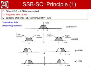
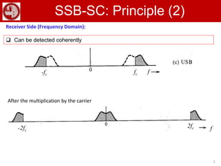
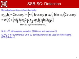
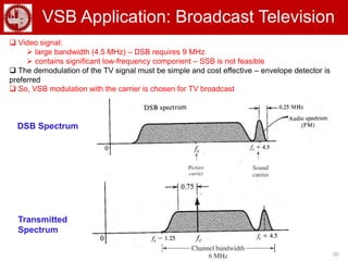
Communication Theory
Single-sideband Suppressed carrier
(SSB-SC) Modulation
f-B -B
M( f )
2
SSB-SC: Principle (1)
 Either USB or LSB is transmitted
 Required BW: B Hz
 Spectral efficiency (SE) is improved by 100%
Transmitter Side:
(Frequency Domain)
ffc- fc
- fc
f- fc
fc
ffc- fc
3
SSB-SC: Principle (2)
 Can be detected coherently
Receiver Side (Frequency Domain):
After the multiplication by the carrier
f
f2fc-2fc
fc-fc
f
4
SSB: Time Domain Representation (1)
Hilbert Transform:
        





t
txd
t
x
txHtxh





1
*
1
         fXfHffjXfXh  sgn
   








0,.1
0,.1
sgn
2
2
fej
fej
fjfH
j
j


 Thus, a Hilbert transformer is an ideal phase shifter that shifts the phase of every spectral
component by -π/2
 Difficult to achieve such sharp change in phase response
 fj
t
sgn1 

Thus,
f
θh (f)
f
|H (f)|
5
SSB: Time Domain Representation (2)
          
    fjMfM
ffMfufMfM
h

2
1
sgn1
2
1
          
    fjMfM
ffMfufMfM
h

2
1
sgn1
2
1
SSB:
M (f)
M+ (f)
M_ (f)
f
f
f
B
-B
-B
B
     ffjMfMNote h sgn: 
6
SSB: Time Domain Representation (3)
     
         chchcc
ccUSB
ffMffM
j
ffMffM
ffMffMf

 
2
1
2
1

Hence,
Similarly,
M+ (f-fc)
M+ (f+fc) M- (f-fc)
M- (f+fc)
fc f
fc f-fc
-fc
USB
LSB
7
Generation of SSB-SC
Generation of SSB-SC:
1. Phase-shift method: requires ideal Hilbert phase shifter
2. Selective filtering method (most commonly used): First, DSB-SC signal is
generated and then passed through a band pass filter for selecting the desired
band. Requires ideal filter or null around DC.
3. Weaver method: Uses two stages of modulation (SSB using selective filtering)
– first using a smaller carrier frequency fc1 and then again using a higher carrier
frequency fc. Thus achieves a gap of 2fc1 for second stage selective filtering.
8
SSB-SC: Detection
      
        


c
ttmttmtm
tttmttmtt
chc
cchccSSB



2carrierwithsignalSCSSB
2sin2cos
cos2sincoscos2



Demodulation using a coherent detector:
 An LPF will suppress unwanted SSB terms and produce m(t)
 Any of the synchronous DSB-SC demodulators can be used for demodulating
SSB-SC signal
9
Comparison between AM, DSB-SC and SSB-SC
AM (DSB-WC) DSB-SC SSB-SC
Modulation Simple Simple Costly and Complex
(difficult to generate)
Demodulation Both envelope
detection and
coherent
detection
Coherent detection
=> Costly and
complex
Coherent detection
=> Costly and complex
Power Efficiency Max 33 %
=> Inefficient
Better
=> Efficient
Better
=> Efficient
Bandwidth (BW)
Requirement
Twice the signal
BW
=> Inefficient
Twice the signal
BW
=> Inefficient
Equal to the signal BW
=> Efficient
10
Single-Sideband With Carrier
(SSB+C) Modulation
11
SSB+C
Envelope detection:
SSB+C Signal:
From Taylor series expansion,
Envelope:
 Not power efficient as significantly higher amplitude is required for carrier
12
Quadrature Amplitude
Modulation (QAM)
13
QAM: Principle
 SSB signals are difficult to generate
 QAM is an attractive alternative to SSB
 Two base band signals, each of bandwidth B Hz, are sent over the same band of
bandwidth 2B Hz (Modulation: DSB –SC)
 The two carriers are of the same frequency with a phase difference of π/2
 QAM is also known as quadrature multiplexing (QM)
Synchronous
detector
14
QAM: Detection (1)
 In-phase (I) Channel
 Quadrature (Q) Channel
        
      ttmttmtm
tttmttmtttx
cc
ccccQAM


2sin2cos
sinsincos2sin2
122
212


        
      ttmttmtm
tttmttmtttx
cc
ccccQAM


2sin2cos
cossincos2cos2
211
211


15
QAM: Detection (2)
 Impact of loss of synchronization
 Loss of power
 interference
Output of the I-channel
Q. Derive the output of the quadrature (Q) channel.
16
Vestigial Sideband (VSB)
Modulation
17
VSB (1): Principle
 SSB signals are difficult to generate and DSB requires twice the signal bandwidth
 VSB is a compromise between DSB and SSB
 VSB inherits the advantages of DSB and SSB, but avoids their disadvantages at a small cost
 Bandwidth of VSB is little (typically 25%) greater than SSB
 VSB is also known as asymmetric sideband system
18
VSB(2): Generation and Detection
        fHffMffMf iccVSB 
        cVSBcVSBcVSB ffffttte   cos2
        fHfffffM ocVSBcVSB  
BPF
Hi(f)
LPF
Ho(f)
Coherent detection:
VSB signal generation:
 
   
Bf
ffHffH
fH
cici
o 

 ||,
1
Hi(f) = Vestigial
shaping filter Synchronous
detection
 fHi
   cici ffHffH 
19
VSB (3): Example
The carrier frequency is 20 kHz. Baseband signal bandwidth is 6 kHz. Hi(f) is
shown if fig (a). Determine H0(f).
Solution:
 fHo
20
VSB Application: Broadcast Television
 Video signal:
 large bandwidth (4.5 MHz) – DSB requires 9 MHz
 contains significant low-frequency component – SSB is not feasible
 The demodulation of the TV signal must be simple and cost effective – envelope detector is
preferred
 So, VSB modulation with the carrier is chosen for TV broadcast
DSB Spectrum
Transmitted
Spectrum
21
End of AM

Single Sideband Suppressed Carrier (SSB-SC)

  • 1.
  • 2.
    f-B -B M( f) 2 SSB-SC: Principle (1)  Either USB or LSB is transmitted  Required BW: B Hz  Spectral efficiency (SE) is improved by 100% Transmitter Side: (Frequency Domain) ffc- fc - fc f- fc fc ffc- fc
  • 3.
    3 SSB-SC: Principle (2) Can be detected coherently Receiver Side (Frequency Domain): After the multiplication by the carrier f f2fc-2fc fc-fc f
  • 4.
    4 SSB: Time DomainRepresentation (1) Hilbert Transform:               t txd t x txHtxh      1 * 1          fXfHffjXfXh  sgn             0,.1 0,.1 sgn 2 2 fej fej fjfH j j    Thus, a Hilbert transformer is an ideal phase shifter that shifts the phase of every spectral component by -π/2  Difficult to achieve such sharp change in phase response  fj t sgn1   Thus, f θh (f) f |H (f)|
  • 5.
    5 SSB: Time DomainRepresentation (2)                fjMfM ffMfufMfM h  2 1 sgn1 2 1                fjMfM ffMfufMfM h  2 1 sgn1 2 1 SSB: M (f) M+ (f) M_ (f) f f f B -B -B B      ffjMfMNote h sgn: 
  • 6.
    6 SSB: Time DomainRepresentation (3)                chchcc ccUSB ffMffM j ffMffM ffMffMf    2 1 2 1  Hence, Similarly, M+ (f-fc) M+ (f+fc) M- (f-fc) M- (f+fc) fc f fc f-fc -fc USB LSB
  • 7.
    7 Generation of SSB-SC Generationof SSB-SC: 1. Phase-shift method: requires ideal Hilbert phase shifter 2. Selective filtering method (most commonly used): First, DSB-SC signal is generated and then passed through a band pass filter for selecting the desired band. Requires ideal filter or null around DC. 3. Weaver method: Uses two stages of modulation (SSB using selective filtering) – first using a smaller carrier frequency fc1 and then again using a higher carrier frequency fc. Thus achieves a gap of 2fc1 for second stage selective filtering.
  • 8.
    8 SSB-SC: Detection                  c ttmttmtm tttmttmtt chc cchccSSB    2carrierwithsignalSCSSB 2sin2cos cos2sincoscos2    Demodulation using a coherent detector:  An LPF will suppress unwanted SSB terms and produce m(t)  Any of the synchronous DSB-SC demodulators can be used for demodulating SSB-SC signal
  • 9.
    9 Comparison between AM,DSB-SC and SSB-SC AM (DSB-WC) DSB-SC SSB-SC Modulation Simple Simple Costly and Complex (difficult to generate) Demodulation Both envelope detection and coherent detection Coherent detection => Costly and complex Coherent detection => Costly and complex Power Efficiency Max 33 % => Inefficient Better => Efficient Better => Efficient Bandwidth (BW) Requirement Twice the signal BW => Inefficient Twice the signal BW => Inefficient Equal to the signal BW => Efficient
  • 10.
  • 11.
    11 SSB+C Envelope detection: SSB+C Signal: FromTaylor series expansion, Envelope:  Not power efficient as significantly higher amplitude is required for carrier
  • 12.
  • 13.
    13 QAM: Principle  SSBsignals are difficult to generate  QAM is an attractive alternative to SSB  Two base band signals, each of bandwidth B Hz, are sent over the same band of bandwidth 2B Hz (Modulation: DSB –SC)  The two carriers are of the same frequency with a phase difference of π/2  QAM is also known as quadrature multiplexing (QM) Synchronous detector
  • 14.
    14 QAM: Detection (1) In-phase (I) Channel  Quadrature (Q) Channel                ttmttmtm tttmttmtttx cc ccccQAM   2sin2cos sinsincos2sin2 122 212                  ttmttmtm tttmttmtttx cc ccccQAM   2sin2cos cossincos2cos2 211 211  
  • 15.
    15 QAM: Detection (2) Impact of loss of synchronization  Loss of power  interference Output of the I-channel Q. Derive the output of the quadrature (Q) channel.
  • 16.
  • 17.
    17 VSB (1): Principle SSB signals are difficult to generate and DSB requires twice the signal bandwidth  VSB is a compromise between DSB and SSB  VSB inherits the advantages of DSB and SSB, but avoids their disadvantages at a small cost  Bandwidth of VSB is little (typically 25%) greater than SSB  VSB is also known as asymmetric sideband system
  • 18.
    18 VSB(2): Generation andDetection         fHffMffMf iccVSB          cVSBcVSBcVSB ffffttte   cos2         fHfffffM ocVSBcVSB   BPF Hi(f) LPF Ho(f) Coherent detection: VSB signal generation:       Bf ffHffH fH cici o    ||, 1 Hi(f) = Vestigial shaping filter Synchronous detection
  • 19.
     fHi   cici ffHffH  19 VSB (3): Example The carrier frequency is 20 kHz. Baseband signal bandwidth is 6 kHz. Hi(f) is shown if fig (a). Determine H0(f). Solution:  fHo
  • 20.
    20 VSB Application: BroadcastTelevision  Video signal:  large bandwidth (4.5 MHz) – DSB requires 9 MHz  contains significant low-frequency component – SSB is not feasible  The demodulation of the TV signal must be simple and cost effective – envelope detector is preferred  So, VSB modulation with the carrier is chosen for TV broadcast DSB Spectrum Transmitted Spectrum
  • 21.