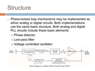
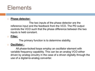
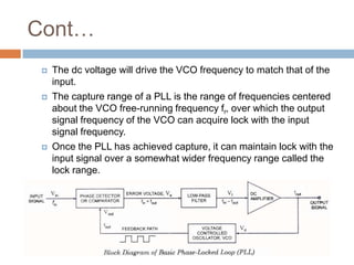
TOPIC OF PRESENTATION:PHASE LOCKED
LOOP
Phase Locked Loop






A phase-locked loop or phase lock loop (PLL)
is a control system that generates an
output signal whose phase is related to the phase
of an input "reference" signal.
It is an electronic circuit consisting of a variable
frequency oscillator and a phase detector.
This circuit compares the phase of the input signal
with the phase of the signal derived from its output
oscillator and adjusts the frequency of its oscillator
to keep the phases matched.
Structure


Phase-locked loop mechanisms may be implemented as
either analog or digital circuits. Both implementations
use the same basic structure. Both analog and digital
PLL circuits include these basic elements:
 Phase detector
 Low-pass filter
 Voltage controlled oscillator
Elements


Phase detector:
The two inputs of the phase detector are the
reference input and the feedback from the VCO. The PD output
controls the VCO such that the phase difference between the two
inputs is held constant.



Filter:

The primary function is to determine stability.


Oscillator :
All phase-locked loops employ an oscillator element with
variable frequency capability. This can be an analog VCO either
driven by analog circuitry in the case of a driven digitally through the
use of a digital-to-analog converter.
Elements


Feedback path and optional divider:
PLLs may include a divider between the
oscillator and the feedback input to the phase detector
to produce a frequency synthesizer.
An Example Digital Divider (by 4) for use in the
Feedback Path of a Multiplying PLL
Operating Principle
Phase Detector
 A phase detector is basically a comparator that
compares the input frequency fin with feedback
frequency fout.
 The phase detector receives two digital signals, one
from the input, the other feedback from the output.
 The loop is locked when these two signals are of the
same frequency and have a fixed phase difference
 When the input signal frequency is the same as that
from the VCO to the PC, the voltage, Vd, taken as
output is the value required to hold the VCO in lock
with the input signal.

Cont…
Low-pass filter
 Low-pass filter is used to remove high frequency
components and noise from the output of the phase
detector.
 Voltage Controlled Oscillator (VCO)
 Voltage-controlled oscillator generates frequency
controlled by input voltage. The dc level output of a
low-pass filter is applied as control signal to the
voltage-controlled oscil-lator (VCO).
 The VCO frequency is adjusted till it becomes equal
to the frequency of the input signal. During this
adjustment, PLL goes through three stages-free
running, capture and phase lock.

Cont…






The dc voltage will drive the VCO frequency to match that of the
input.
The capture range of a PLL is the range of frequencies centered
about the VCO free-running frequency fr, over which the output
signal frequency of the VCO can acquire lock with the input
signal frequency.
Once the PLL has achieved capture, it can maintain lock with the
input signal over a somewhat wider frequency range called the
lock range.
Application:


Phase-locked loops are widely



Used for synchronization purposes; in
space communications for coherent demodulation.



Used to demodulate frequency-modulated signals.



In radio transmitters, a PLL is used to synthesize new
frequencies which are a multiple of a reference frequency
Demodulation of both FM and AM signals.





Recovery of small signals that otherwise would be lost in
noise.
Practical Application:
In digital wireless communication system (i.e
GSM), PLLs are used to provide the local
oscillator up-conversion during transmission
and down-conversion during reception.
 In most cellular handsets this function
has been largely integrated into a
single integrated circuit to reduce
the cost and size of the handset.

THANK YOU
QUESTIONS?

Phase locked loop

  • 1.
  • 2.
    Phase Locked Loop    Aphase-locked loop or phase lock loop (PLL) is a control system that generates an output signal whose phase is related to the phase of an input "reference" signal. It is an electronic circuit consisting of a variable frequency oscillator and a phase detector. This circuit compares the phase of the input signal with the phase of the signal derived from its output oscillator and adjusts the frequency of its oscillator to keep the phases matched.
  • 3.
    Structure  Phase-locked loop mechanismsmay be implemented as either analog or digital circuits. Both implementations use the same basic structure. Both analog and digital PLL circuits include these basic elements:  Phase detector  Low-pass filter  Voltage controlled oscillator
  • 4.
    Elements  Phase detector: The twoinputs of the phase detector are the reference input and the feedback from the VCO. The PD output controls the VCO such that the phase difference between the two inputs is held constant.  Filter: The primary function is to determine stability.  Oscillator : All phase-locked loops employ an oscillator element with variable frequency capability. This can be an analog VCO either driven by analog circuitry in the case of a driven digitally through the use of a digital-to-analog converter.
  • 5.
    Elements  Feedback path andoptional divider: PLLs may include a divider between the oscillator and the feedback input to the phase detector to produce a frequency synthesizer. An Example Digital Divider (by 4) for use in the Feedback Path of a Multiplying PLL
  • 6.
    Operating Principle Phase Detector A phase detector is basically a comparator that compares the input frequency fin with feedback frequency fout.  The phase detector receives two digital signals, one from the input, the other feedback from the output.  The loop is locked when these two signals are of the same frequency and have a fixed phase difference  When the input signal frequency is the same as that from the VCO to the PC, the voltage, Vd, taken as output is the value required to hold the VCO in lock with the input signal. 
  • 7.
    Cont… Low-pass filter  Low-passfilter is used to remove high frequency components and noise from the output of the phase detector.  Voltage Controlled Oscillator (VCO)  Voltage-controlled oscillator generates frequency controlled by input voltage. The dc level output of a low-pass filter is applied as control signal to the voltage-controlled oscil-lator (VCO).  The VCO frequency is adjusted till it becomes equal to the frequency of the input signal. During this adjustment, PLL goes through three stages-free running, capture and phase lock. 
  • 8.
    Cont…    The dc voltagewill drive the VCO frequency to match that of the input. The capture range of a PLL is the range of frequencies centered about the VCO free-running frequency fr, over which the output signal frequency of the VCO can acquire lock with the input signal frequency. Once the PLL has achieved capture, it can maintain lock with the input signal over a somewhat wider frequency range called the lock range.
  • 9.
    Application:  Phase-locked loops arewidely  Used for synchronization purposes; in space communications for coherent demodulation.  Used to demodulate frequency-modulated signals.  In radio transmitters, a PLL is used to synthesize new frequencies which are a multiple of a reference frequency Demodulation of both FM and AM signals.   Recovery of small signals that otherwise would be lost in noise.
  • 10.
    Practical Application: In digitalwireless communication system (i.e GSM), PLLs are used to provide the local oscillator up-conversion during transmission and down-conversion during reception.  In most cellular handsets this function has been largely integrated into a single integrated circuit to reduce the cost and size of the handset. 
  • 11.
  • 12.