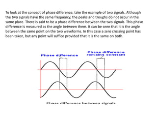
The document provides an overview of phase locked loops (PLLs). It discusses:
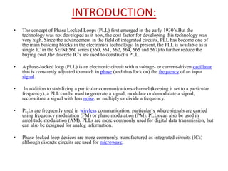
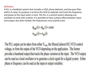
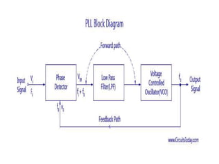
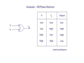
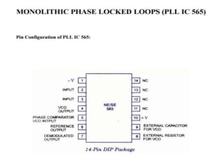
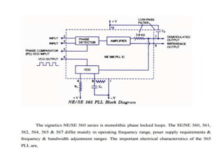
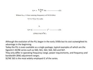
- The basic components of a PLL including a phase detector, low pass filter, and voltage controlled oscillator (VCO). The phase detector compares the phase difference between an input signal and VCO output.
- Applications of PLLs such as frequency modulation decoding, frequency synthesis, and clock generation.
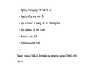
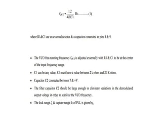
- Key parameters like lock range, which is the range of input frequencies a PLL can lock onto, and capture range, which is the range a PLL can lock onto when starting unlocked.
- Operation of a basic PLL, including free running, capture, and phase lock stages where the VCO frequency adjusts until matching the