Download as PDF, PPTX


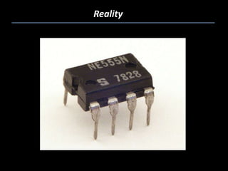

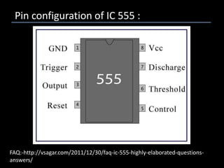
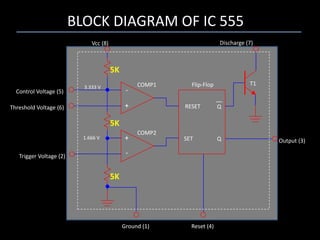

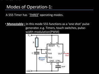

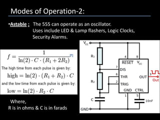


The 555 timer IC is a versatile integrated circuit that can generate accurate time delays and oscillations. Introduced in 1972, it remains widely used due to its low cost, ease of use, and stability. The 555 timer can operate in three modes - monostable, astable, and bistable - making it suitable for applications like timers, oscillators, and flip-flops. It consists of 15 resistors, 2 diodes, and 25 transistors packaged in an 8-pin DIP. The 556 and 558 ICs are dual and quad versions containing multiple 555 timers in a single package.