Downloaded 76 times
![Route Redistribution
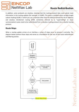
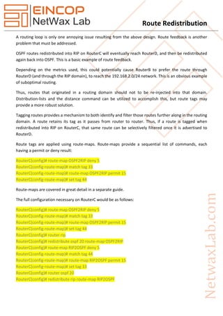
Route maps are extremely flexible and are used in a number routing scenarios including:
1. Controlling redistribution based on permit/deny statements
2. Defining policies in policy-based routing (PBR)
3. Add more mature decision making to NAT decisions than simply using static translations
4. When implementing BGP PBR
Basic Route Map Configuration
R1(config)# route-map {tag} permit | deny [sequence_number]
That is how all route maps begin. Permit means that any traffic matching the match statement that
follows is processed by the route map. Deny means that any traffic matching the match statement that
follows is NOT processed by the route map. Know the difference.
Configuring Redistribution
To configure redistribution between routing protocols, the redistribute protocol command is used under
the routing protocol that receives the routes.
R1(config-router)# redistribute protocol [AS/process-ID] [metric metric-vlaue]
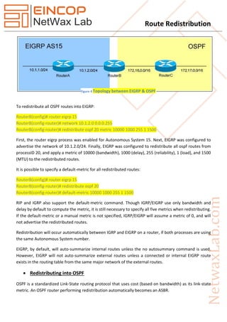
EIGRP Redistribution Example
R1(config)# router eigrp 10
R1(config-router)# redistribute ospf 20 metric 1000 100 255 1 1500
The example above shows OSPF being redistruted into EIGRP with a metric of 1000 100 255 1 1500. That
is a lot of different numbers for an EIGRP cost! That’s because EIGRP redistribution metric requires you
to input all of the metric calculation manually:
1. bandwidth
2. delay
3. reliability
4. loading
5. mtu
Both RIP and EIGRP require the use the metric keyword.
Redistributing into RIP
RIP is a standardized Distance-Vector routing protocol that uses hop-count as its distance metric.
Consider the following example:](https://image.slidesharecdn.com/nxld40routeredistribution-150429020234-conversion-gate01/85/Route-Redistribution-3-320.jpg)


![Route Redistribution
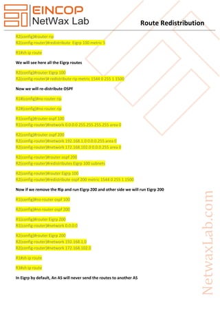
R2(config-of)#no shut
R3(config)#int fa0/0
R3(config-if)#ip add 172.168.103.1 255.255.255.0
R3(config-of)#no shut
R3(config)#int s0/0
R3(config-if)#ip add 192.168.2.2 255.255.255.0
R3(config-of)#no shut
R1(config)#router rip
R1(config-router)#version 2
R1(config-router)#network 0.0.0.0
R1(config-router)#no auto-summary
R2(config)#router rip
R2(config-router)#version 2
R2(config-router)#network 172.168.102.0
R2(config-router)#network 192.168.1.0
R2(config-router)#no auto-summary
R2(config)#router Eigrp 100
R2(config-router)#network 192.168.2.0
R2(config-router)#no auto-summary
R3(config)#router Eigrp 100
R3(config-router)#network 0.0.0.0
R3(config-router)#no auto-summary
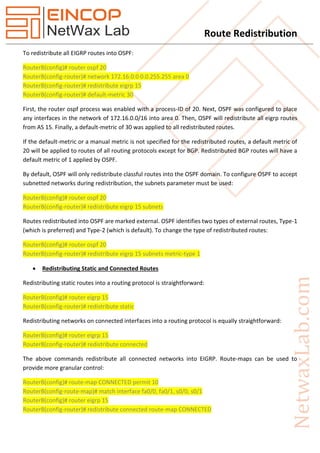
R1#sh ip route
172.168.0.0/24 is subnetted, 2 subnets
C 172.168.101.0 is directly connected, FastEthernet0/0
R 172.168.102.0 [120/1] via 192.168.1.2, 00:00:01, Serial0/0
C 192.168.1.0/24 is directly connected, Serial0/0
We cannot see here R3 routes
R3#sh ip route
172.168.0.0/24 is subnetted, 1 subnets
C 172.168.103.0 is directly connected, FastEthernet0/0
C 192.168.2.0/24 is directly connected, Serial0/0
We can see here only connected routes
R1#ping 172.168.103.1 repeat 1000](https://image.slidesharecdn.com/nxld40routeredistribution-150429020234-conversion-gate01/85/Route-Redistribution-12-320.jpg)
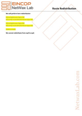

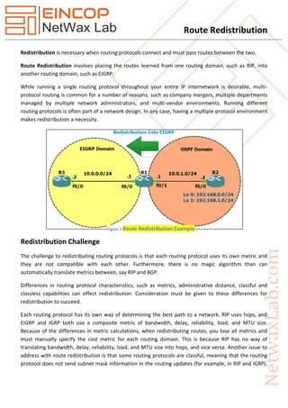
Route redistribution is essential for connecting different routing protocols, which may have incompatible metrics and characteristics. Challenges include the potential for routing loops and suboptimal paths due to varying administrative distances. Solutions such as route maps, access lists, and route tags can help manage and prevent issues during the redistribution process.