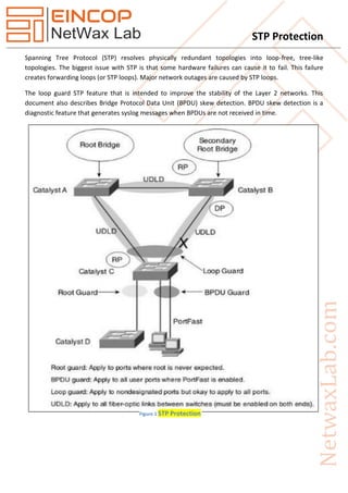
Spanning Tree Protocol (STP) resolves physically redundant topologies into loop-free, tree-like
topologies. The biggest issue with STP is that some hardware failures can cause it to fail. This failure
creates forwarding loops (or STP loops). Major network outages are caused by STP loops.
The loop guard STP feature that is intended to improve the stability of the Layer 2 networks. This
document also describes Bridge Protocol Data Unit (BPDU) skew detection. BPDU skew detection is a
diagnostic feature that generates syslog messages when BPDUs are not received in time.
Spanning Tree Protocol (STP) is a network protocol designed to prevent layer 2 loops. It is standardized as IEEE 802.D protocol. STP blocks some ports on switches with redundant links to prevent broadcast storms and ensure loop-free topology. With STP in place, you can have redundant links between switches in order to provide redundancy.
It prevents a network from frame looping by putting some interfaces in forwarding state & some
interfaces in blocking state.
Whenever two or more switches are connected with each other for redundancy purpose loop can occur.
STP Protocol is used to prevent the loop. STP is layer 2 Protocol & by default it is enabled on switches.
Difference between Spanning Tree Protocol (STP) and Rapid Spanning Tree
Protocol (RSTP)
1. The main difference between Rapid Spanning Tree Protocol (RSTP IEEE 802.1W) and Spanning
Tree Protocol (STP IEEE 802.1D) is that Rapid Spanning Tree Protocol (RSTP IEEE 802.1W)
assumes the three Spanning Tree Protocol (STP) ports states Listening, Blocking, and Disabled are
same (these states do not forward Ethernet frames and they do not learn MAC addresses).
Hence Rapid Spanning Tree Protocol (RSTP IEEE 802.1W) places them all into a new called
Discarding state. Learning and forwarding ports remain more or less the same.
Spanning Tree Protocol (STP) is standardized as IEEE 802.1D.
Is a network protocol that ensures a loop-free topology for any bridged Ethernet local area network.
Free CCNP switching workbook by networkershome pdfNetworkershome
ccnp workbook and lab manual by NETWORKERS HOME. NETWORKERS HOME understand the importance of CCNP switching workbook when it comes Cisco certification which is why we offered free CCNP switching workbook.
MOBILE INTERNET PROTOCOL AND TRANSPORT LAYER
Overview of Mobile IP – Features of Mobile IP – Key Mechanism in Mobile IP – route Optimization. Overview of TCP/IP – Architecture of TCP/IP- Adaptation of TCP Window – Improvement in TCP Performance.
IP Address is a unique identification given to Host, network device, server for data communication. IP
Address stand for Internet Protocol address, it is an addressing scheme used to identify a system on a
network. It is a unique address that certain electronic devices currently use to communicate with each
other on a network using internet protocol.
A network consists of a collection of computers, printers and other compatible equipment/ hardware
that is connected together so that they can communicate with each other.
Networking Devices are units that mediate data in a computer network and are also called network equipment. Units which are the last receiver or generate data are called hosts or data terminal equipment.
A VPN (Virtual Private Network) extends a private network across a public network, such as the
Internet.
A VPN is a network that uses a public telecommunication infrastructure, such as the Internet, to provide
remote offices or individual users with secure access to their organization's network. A VPN ensures
privacy through security procedures and tunneling protocols such as the Layer Two Tunneling Protocol
(L2TP). Data is encrypted at the sending end and decrypted at the receiving end.
TCP Intercept was developed to protect servers and other resources from Denial-of-Service (DoS)
attacks, specifically TCP SYN attacks.
Just as the name says, TCP Intercept captures incoming TCP requests. Instead of allowing direct access
to the server, TCP Intercept acts as an intermediary, establishing a connection to the server on behalf of
the requesting client.
TCP Intercept will block a client if too many incoming connections are attempted.
For some very basic VRF configuration follow the steps:
1. Enters VRF configuration mode and assigns a VRF name.
Router(config)#ip vrf vrf-name
2. Creates a VPN route distinguisher (RD) following one of the 16bit-ASN:32bit-number or 32bitIP:16bit-number explained above
Router(config-vrf)#rd route-distinguisher
3. Creates a list of import and/or export route target communities for the specified VRF.
Router(config-vrf)# route-target {import | export | both} route-distinguisher
4. (Optional step) Associates the specified route map with the VRF.
Router(config-vrf)# import map route-map
Wireless networks come in many different forms, cover various distances, and provide a range of low to
high bandwidth depending on the type installed. Wireless LAN – Wireless LAN enable Laptop users to
access the Network of a company.
In computer networking, a single layer-2 network may be partitioned to create multiple distinct
broadcast domains, which are mutually isolated so that packets can only pass between them via one or
more routers; such a domain is referred to as a virtual local area network, virtual LAN or VLAN.
A virtual local area network (VLAN) is a logical group of workstations, servers and network devices that
appear to be on the same LAN despite their geographical distribution. A VLAN allows a network of
computers and users to communicate in a simulated environment as if they exist in a single LAN and are
sharing a single broadcast and multicast domain.
A Proxy Server is computer that functions as an intermediary between a web browser (such as Internet
Explorer) and the Internet. Proxy servers help improve web performance by storing a copy of frequently
used webpages. When a browser requests a webpage stored in the proxy server's collection (its cache),
it is provided by the proxy server, which is faster than going to the web. Proxy servers also help improve
security by filtering out some web content and malicious software.
A Proxy Server is a server (a computer system or an application) that acts as an intermediary for
requests from clients seeking resources from other servers.
Internet Protocol version 6 (IPv6) is the latest version of the
Internet Protocol (IP), the communications protocol that
provides an identification and location system for computers
on networks and routes traffic across the Internet.
IPv4 & IPv6 are not designed to be interoperable, complicating
the transition to IPv6. However, several IPv6 transition
mechanisms have been devised to permit communication
between IPv4 and IPv6 hosts.
Frame Relay is a high-performance WAN protocol that operates at the physical and data link layers of
the OSI reference model. Frame Relay originally was designed for use across Integrated Services Digital
Network (ISDN) interfaces. Today, it is used over a variety of other network interfaces as well.
Frame relay is a type of WAN connection use to connect one site to many remote sites through a single
physical circuit; this operation makes it easy to construct reliable and inexpensive networks.
The concept of the spanning tree protocol was devised to address broadcast storming. The spanning tree algorithm itself is defined by the IEEE standard 802.1D and its later revisions.
The IEEE Standard 802.1 uses the term bridge to define the spanning tree operation, and uses terms such as Bridge Protocol Data Units and Root Bridge when defining spanning tree protocol functions.
When a bridge receives a frame, it reads the source and destination address fields. The bridge then enters the frame’s source address in its forwarding database. In doing this the bridge associates the frame’s source address with the network attached to the por t on which the frame was received. The bridge also reads the destination address and if it can find this address in its forwarding database, it forwards the frame to the appropriate port. If the bridge does not recognize the destination address, it forwards the frame out from all its por ts except for the one on which the frame was received, and then waits for a reply. This process is known as “flooding”. Similarly, packets with broadcast or multicast destination MAC addresses will be flooded by a bridge.
A significant problem arises where bridges connect via multiple paths. A frame that arrives with an unknown or broadcast/multicast destination address is flooded over all available paths. The arrival of these frames at another network via different paths and bridges produces major problems. The bridges find the same source MAC address arriving on
multiple different por ts, making it impossible to maintain a reliable forwarding database. As a result, increasing numbers of packets will be forwarded to multiple paths. This process is selfperpetuating and produces a condition known as a packet storm, where the increase of circulating frames can eventually overload the network.
In 2001, the IEEE introduced Rapid Spanning Tree Protocol (RSTP) as 802.1w. RSTP provides significantly
faster spanning tree convergence after a topology change, introducing new convergence behavior and
bridge port roles to do this. RSTP was designed to be backwards-compatible with standard STP.
While STP can take 30 to 50 seconds to respond to a topology change, RSTP is typically able to respond
to changes within 3 × Hello times (default: 3 times 2 seconds) or within a few milliseconds of a physical
link failure. The so-called Hello time is an important and configurable time interval that is used by RSTP
for several purposes; its default value is 2 seconds.
Overview of Spanning Tree Protocol (STP & RSTP)Peter R. Egli
Ethernet networks require a loop-free topology, otherwise more and more broadcastand unknown unicast frames would swamp the network (creation of frame duplicates resulting in a broadcast storm). Spanning Tree Protocol (IEEE 802.1D) and its faster successor RSTP (IEEE 802.1w) provide loop prevention in bridged networks by establising a loop-free tree of forwarding paths between any two bridges in a network with multiple physical paths. If a link fails, STP and RSTP automatically establishes a new loop-free topology. This presentation describes in detail how STP and RSTP work along with typical examples.
DevOps and Testing slides at DASA ConnectKari Kakkonen
My and Rik Marselis slides at 30.5.2024 DASA Connect conference. We discuss about what is testing, then what is agile testing and finally what is Testing in DevOps. Finally we had lovely workshop with the participants trying to find out different ways to think about quality and testing in different parts of the DevOps infinity loop.
Builder.ai Founder Sachin Dev Duggal's Strategic Approach to Create an Innova...Ramesh Iyer
In today's fast-changing business world, Companies that adapt and embrace new ideas often need help to keep up with the competition. However, fostering a culture of innovation takes much work. It takes vision, leadership and willingness to take risks in the right proportion. Sachin Dev Duggal, co-founder of Builder.ai, has perfected the art of this balance, creating a company culture where creativity and growth are nurtured at each stage.
The Art of the Pitch: WordPress Relationships and SalesLaura Byrne
Clients don’t know what they don’t know. What web solutions are right for them? How does WordPress come into the picture? How do you make sure you understand scope and timeline? What do you do if sometime changes?
All these questions and more will be explored as we talk about matching clients’ needs with what your agency offers without pulling teeth or pulling your hair out. Practical tips, and strategies for successful relationship building that leads to closing the deal.
GraphRAG is All You need? LLM & Knowledge GraphGuy Korland
Guy Korland, CEO and Co-founder of FalkorDB, will review two articles on the integration of language models with knowledge graphs.
1. Unifying Large Language Models and Knowledge Graphs: A Roadmap.
https://arxiv.org/abs/2306.08302
2. Microsoft Research's GraphRAG paper and a review paper on various uses of knowledge graphs:
https://www.microsoft.com/en-us/research/blog/graphrag-unlocking-llm-discovery-on-narrative-private-data/
State of ICS and IoT Cyber Threat Landscape Report 2024 previewPrayukth K V
The IoT and OT threat landscape report has been prepared by the Threat Research Team at Sectrio using data from Sectrio, cyber threat intelligence farming facilities spread across over 85 cities around the world. In addition, Sectrio also runs AI-based advanced threat and payload engagement facilities that serve as sinks to attract and engage sophisticated threat actors, and newer malware including new variants and latent threats that are at an earlier stage of development.
The latest edition of the OT/ICS and IoT security Threat Landscape Report 2024 also covers:
State of global ICS asset and network exposure
Sectoral targets and attacks as well as the cost of ransom
Global APT activity, AI usage, actor and tactic profiles, and implications
Rise in volumes of AI-powered cyberattacks
Major cyber events in 2024
Malware and malicious payload trends
Cyberattack types and targets
Vulnerability exploit attempts on CVEs
Attacks on counties – USA
Expansion of bot farms – how, where, and why
In-depth analysis of the cyber threat landscape across North America, South America, Europe, APAC, and the Middle East
Why are attacks on smart factories rising?
Cyber risk predictions
Axis of attacks – Europe
Systemic attacks in the Middle East
Download the full report from here:
https://sectrio.com/resources/ot-threat-landscape-reports/sectrio-releases-ot-ics-and-iot-security-threat-landscape-report-2024/
Connector Corner: Automate dynamic content and events by pushing a buttonDianaGray10
Here is something new! In our next Connector Corner webinar, we will demonstrate how you can use a single workflow to:
Create a campaign using Mailchimp with merge tags/fields
Send an interactive Slack channel message (using buttons)
Have the message received by managers and peers along with a test email for review
But there’s more:
In a second workflow supporting the same use case, you’ll see:
Your campaign sent to target colleagues for approval
If the “Approve” button is clicked, a Jira/Zendesk ticket is created for the marketing design team
But—if the “Reject” button is pushed, colleagues will be alerted via Slack message
Join us to learn more about this new, human-in-the-loop capability, brought to you by Integration Service connectors.
And...
Speakers:
Akshay Agnihotri, Product Manager
Charlie Greenberg, Host
GDG Cloud Southlake #33: Boule & Rebala: Effective AppSec in SDLC using Deplo...James Anderson
Effective Application Security in Software Delivery lifecycle using Deployment Firewall and DBOM
The modern software delivery process (or the CI/CD process) includes many tools, distributed teams, open-source code, and cloud platforms. Constant focus on speed to release software to market, along with the traditional slow and manual security checks has caused gaps in continuous security as an important piece in the software supply chain. Today organizations feel more susceptible to external and internal cyber threats due to the vast attack surface in their applications supply chain and the lack of end-to-end governance and risk management.
The software team must secure its software delivery process to avoid vulnerability and security breaches. This needs to be achieved with existing tool chains and without extensive rework of the delivery processes. This talk will present strategies and techniques for providing visibility into the true risk of the existing vulnerabilities, preventing the introduction of security issues in the software, resolving vulnerabilities in production environments quickly, and capturing the deployment bill of materials (DBOM).
Speakers:
Bob Boule
Robert Boule is a technology enthusiast with PASSION for technology and making things work along with a knack for helping others understand how things work. He comes with around 20 years of solution engineering experience in application security, software continuous delivery, and SaaS platforms. He is known for his dynamic presentations in CI/CD and application security integrated in software delivery lifecycle.
Gopinath Rebala
Gopinath Rebala is the CTO of OpsMx, where he has overall responsibility for the machine learning and data processing architectures for Secure Software Delivery. Gopi also has a strong connection with our customers, leading design and architecture for strategic implementations. Gopi is a frequent speaker and well-known leader in continuous delivery and integrating security into software delivery.
Epistemic Interaction - tuning interfaces to provide information for AI supportAlan Dix
Paper presented at SYNERGY workshop at AVI 2024, Genoa, Italy. 3rd June 2024
https://alandix.com/academic/papers/synergy2024-epistemic/
As machine learning integrates deeper into human-computer interactions, the concept of epistemic interaction emerges, aiming to refine these interactions to enhance system adaptability. This approach encourages minor, intentional adjustments in user behaviour to enrich the data available for system learning. This paper introduces epistemic interaction within the context of human-system communication, illustrating how deliberate interaction design can improve system understanding and adaptation. Through concrete examples, we demonstrate the potential of epistemic interaction to significantly advance human-computer interaction by leveraging intuitive human communication strategies to inform system design and functionality, offering a novel pathway for enriching user-system engagements.
Generating a custom Ruby SDK for your web service or Rails API using Smithyg2nightmarescribd
Have you ever wanted a Ruby client API to communicate with your web service? Smithy is a protocol-agnostic language for defining services and SDKs. Smithy Ruby is an implementation of Smithy that generates a Ruby SDK using a Smithy model. In this talk, we will explore Smithy and Smithy Ruby to learn how to generate custom feature-rich SDKs that can communicate with any web service, such as a Rails JSON API.
UiPath Test Automation using UiPath Test Suite series, part 3DianaGray10
Welcome to UiPath Test Automation using UiPath Test Suite series part 3. In this session, we will cover desktop automation along with UI automation.
Topics covered:
UI automation Introduction,
UI automation Sample
Desktop automation flow
Pradeep Chinnala, Senior Consultant Automation Developer @WonderBotz and UiPath MVP
Deepak Rai, Automation Practice Lead, Boundaryless Group and UiPath MVP
Key Trends Shaping the Future of Infrastructure.pdfCheryl Hung
Keynote at DIGIT West Expo, Glasgow on 29 May 2024.
Cheryl Hung, ochery.com
Sr Director, Infrastructure Ecosystem, Arm.
The key trends across hardware, cloud and open-source; exploring how these areas are likely to mature and develop over the short and long-term, and then considering how organisations can position themselves to adapt and thrive.
Encryption in Microsoft 365 - ExpertsLive Netherlands 2024Albert Hoitingh
In this session I delve into the encryption technology used in Microsoft 365 and Microsoft Purview. Including the concepts of Customer Key and Double Key Encryption.
Assuring Contact Center Experiences for Your Customers With ThousandEyes
STP Protection
1. STP Protection
Spanning Tree Protocol (STP) resolves physically redundant topologies into loop-free, tree-like
topologies. The biggest issue with STP is that some hardware failures can cause it to fail. This failure
creates forwarding loops (or STP loops). Major network outages are caused by STP loops.
The loop guard STP feature that is intended to improve the stability of the Layer 2 networks. This
document also describes Bridge Protocol Data Unit (BPDU) skew detection. BPDU skew detection is a
diagnostic feature that generates syslog messages when BPDUs are not received in time.
Figure 1 STP Protection
2. STP Protection
Feature Availability
CatOS
1. The STP loop guard feature was introduced in CatOS version 6.2.1 of the Catalyst software for
Catalyst 4000 and Catalyst 5000 platforms and in version 6.2.2 for the Catalyst 6000 platform.
2. The BPDU skew detection feature was introduced in CatOS version 6.2.1 of the Catalyst software
for Catalyst 4000 and Catalyst 5000 platforms and in version 6.2.2 for the Catalyst 6000 platform.
Cisco IOS
1. The STP loop guard feature was introduced in Cisco IOS Software Release 12.1(12c)EW for
Catalyst 4500 switches and Cisco IOS Software Release 12.1(11b)EX for Catalyst 6500.
2. The BPDU skew detection feature is not supported in Catalyst switches running Cisco IOS system
software.
Brief Summary of STP Port Roles
Internally, STP assigns to each bridge (or switch) port a role that is based on configuration, topology,
relative position of the port in the topology, and other considerations. The port role defines the
behavior of the port from the STP point of view. Based on the port role, the port either sends or receives
STP BPDUs and forwards or blocks the data traffic. This list provides a brief summary of each STP port
role:
1. Designated- One designated port is elected per link (segment). The designated port is the port
closest to the root bridge. This port sends BPDUs on the link (segment) and forwards traffic
towards the root bridge. In an STP converged network, each designated port is in the STP
forwarding state.
2. Root- The bridge can have only one root port. The root port is the port that leads to the root
bridge. In an STP converged network, the root port is in the STP forwarding state.
3. Alternate- Alternate ports lead to the root bridge, but are not root ports. The alternate ports
maintain the STP blocking state.
4. Backup- This is a special case when two or more ports of the same bridge (switch) are connected
together, directly or through shared media. In this case, one port is designated, and the
remaining ports block. The role for this port is backup.
3. STP Protection
Root Guard
It is a security feature of STP. It protects our network from root bridge changes. After enabling root
guard, if any switch receives BPDU then it will put that port in root inconsistent state. It should apply on
all designated trunk ports. We should not configure this feature between those switches which are
performing STP load balancing.
A feature when it receives BPDU then it put that port in error disable or root inconsistent state.
Loop Guard
It is a feature of STP. It should be enabling on all the Non-DP ports (root & blocking).
After enabling loop guard if switch is receiving BPDUs on a switchport constantly then it will remain in
working mode, but if it stops to receive BPDUs on switchport then it will put that switch port in loop
inconsistent mode.
It is a feature when it receives a BPDU, it remain silent, if it will not receive BPDU then it will put that
port in loop inconsistent state or error disable state.
(Note: always applied on Non-DP ports.)
Consider this example in order to illustrate this behavior:
Switch A is the root switch. Switch C does not receive BPDUs from switch B due to unidirectional link
failure on the link between switch B and switch C.
Without loop guard, the STP blocking port on switch C transitions to the STP listening state when the
max_age timer expires, and then it transitions to the forwarding state in two times the forward_delay
time. This situation creates a loop.
Figure 2
4. STP Protection
With loop guard enabled, the blocking port on switch C transitions into STP loop-inconsistent state when
the max_age timer expires. A port in STP loop-inconsistent state does not pass user traffic, so a loop is
not created. (The loop-inconsistent state is effectively equal to blocking state.)
BPDU Guard
A feature when it receives BPDU it put that port in error disable mode.
(Note: Always applied on access port.)
For enable – shut & no shut
BPDU Filter
When we enable port fast then we save only 32 sec convergence time but STP is still working on the
port, if we want to block STP completely on a port then we have to use BPDU filter.
(Note: Always applied on access port.)
Figure 3
Figure 4
5. STP Protection
BPDU Skew Detection
STP operation relies heavily on the timely reception of BPDUs. At every hello_time message (2 seconds
by default), the root bridge sends BPDUs. Non-root bridges do not regenerate BPDUs for each
hello_time message, but they receive relayed BPDUs from the root bridge. Therefore, every non-root
bridge should receive BPDUs on every VLAN for each hello_time message. In some cases, BPDUs are
lost, or the bridge CPU is too busy to relay BPDU in a timely manner. These issues, as well as other
issues, can cause BPDUs to arrive late (if they arrive at all). This issue potentially compromises the
stability of the spanning tree topology.
BPDU skew detection allows the switch to keep track of BPDUs that arrive late and to notify the
administrator with syslog messages. For every port on which a BPDU has ever arrived late (or has
skewed), skew detection reports the most recent skew and the duration of the skew (latency). It also
reports the longest BPDU delay on this particular port.
In order to protect the bridge CPU from overload, a syslog message is not generated every time BPDU
skewing occurs. Messages are rate-limited to one message every 60 seconds. However, should the delay
of BPDU exceed max_age divided by 2 (which equals 10 seconds by default), the message is immediately
printed.
(Note: BPDU skew detection is a diagnostic feature. Upon detection of BPDU skewing, it sends a syslog
message. BPDU skew detection takes no further corrective action.)
This is an example of a syslog message generated by BPDU skew detection:
%SPANTREE-2-BPDU_SKEWING: BPDU skewed with a delay of 10 secs (max_age/2)
UDLD (Unidirectional Link Detection)
Figure 5 UDLD
6. STP Protection
UDLD was designed for fiber cables if there is an odd link failure in this situation link status would be up
but communication is not possible. To detect this problem we enable UDLD. UDLD sends special
message over the trunk and it hope that another switch must echo the same message with same link. If
a switch receives echo message it means link is fine. Otherwise there is a problem with link. UDLD takes
action according to its modes.
UDLD Mode
1. Normal- Syslog Message send
2. Aggressive-
(i) Re-establish
(ii) Shut
(iii) Message
Loop Guard versus UDLD
Loop guard and Unidirectional Link Detection (UDLD) functionality overlap, partly in the sense that both
protect against STP failures caused by unidirectional links. However, these two features differ in
functionality and how they approach the problem. This table describes loop guard and UDLD
functionality:
Functionality Loop Guard UDLD
Configuration Per-port Per-port
Action granularity Per-VLAN Per-port
Autorecover Yes Yes, with err-disable
timeout feature
Protection against STP failures caused
by unidirectional links
Yes, when enabled on all root
and alternate ports in
redundant topology
Yes, when enabled on all
links in redundant
topology
Protection against STP failures caused
by problems in the software
(designated switch does not send
BPDU)
Yes No
Protection against miswiring. No Yes
7. STP Protection
Example
Root Guard
We enable root guard on all the Designated Port of Switches.
Sw4#sh spanning tree
Here we can see the Sw4 is the root bridge
All the ports of Sw4 is DP
Sw4 (config) #int range fa0/19 -24
Sw4 (config-if) #spanning-tree guard root
Sw3#sh spanning-tree
There is no DP port
Sw2#sh spanning-tree
21 to 24 is DP
Sw2 (config) #int range fa0/21 – 24
Sw2 (config-if) #spanning-tree guard root
Sw1#sh spanning-tree
DP is 19 and 20
Figure 6 STP Topology
8. STP Protection
Sw1 (config) #int range fa0/19 – 20
Sw1 (config-if) #spanning-tree guard root
Finally we enabled root guard on all the switches DP ports.
Now we will make Sw3 as Root Bridge for vlan 1
Sw3 (config) #spanning-tree vlan 1 priority 0
Sw3#sh spanning-tree
Sw4#sh spanning-tree
Now we can see root guard send the port in root inconsistent mode.
Sw3 (config) #no spanning-tree vlan 1 priority 0
Sw1#sh spanning-tree
Loop Guard
It will apply on all non-DP and blocking port
Sw1#sh spanning-tree
Fa0/21 is the root port
Sw1 (config) #int fa0/21
Sw1 (config-if) #spanning-tree guard loop
Sw4 (config) #int fa0/21
Sw4 (config-if) #spanning-tree bpdufilter enable
Sw1#sh spanning-tree
Sw4 (config) #int fa0/21
Sw4 (config-if) #spanning-tree bpdufilter disable
Sw1#sh spanning-tree
BPDU Guard
Only applied on Access ports
Sw1 (config) #int range fa0/1 – 18
Sw1 (config-if-range) #spanning-tree bpduguard enable
Sw1 (config-if-range) #spanning-tree bpdufilter enable