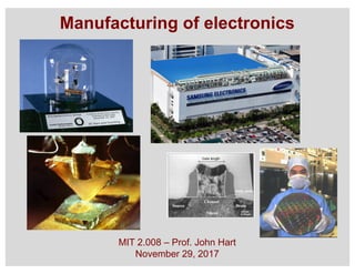
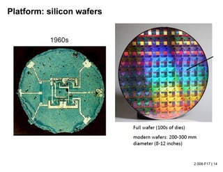
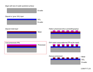
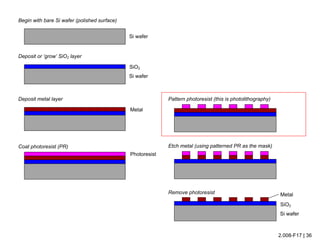
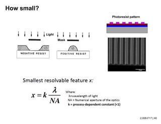
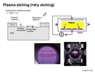
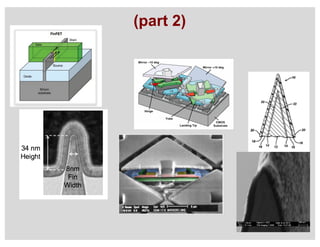
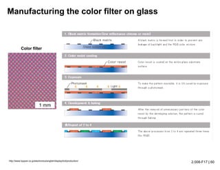
This document summarizes the history and development of semiconductor manufacturing and processing from the 1950s to the present. It outlines key milestones such as the first transistor in 1952, the first microprocessor in the 1970s, and advancements that enabled continued transistor scaling and integration through the 1980s-2000s. The document also provides overviews of the semiconductor manufacturing supply chain, fabrication process steps involving deposition, lithography, and etching, and factors that have driven the semiconductor industry market growth.
This document discusses ceramic properties, applications, and fabrication methods. It provides examples of using ceramics for refractories, die blanks, cutting tools, sensors, and alternative energy applications. Common ceramic fabrication techniques include glass forming, particulate forming, cementation, pressing, sintering, tape casting, and powder methods. Advanced ceramics have applications in heat engines, armor, and electronic packaging due to their high temperature resistance, hardness, and thermal conductivity.
Wire bonding is used to electrically interconnect integrated circuits to packages so they can be handled, tested, and used in electronic products. There are two main types of wire bonding: ball bonding and wedge bonding. Ball bonding uses a capillary tool to form a ball bond on the chip and substrate, while wedge bonding uses a wedge tool. Wire bonding allows for high-speed, economical connections and is the most common interconnection method. It enables signals and power to be distributed from the packaged IC to the rest of the system while also providing mechanical support and environmental protection.
The document discusses wire bonding for MEMS technology. It covers topics like wire bonding equipment, metallurgy considerations for common metal combinations used in wire bonding, shear testing of wire bonds, and process parameters that affect wire bonding results. The document contains diagrams and images to illustrate concepts discussed. It aims to provide an introduction and overview of key aspects of wire bonding.
Hot isostatic pressing (HIP) is a powder metallurgy technique that uses high temperatures and pressures to densify metals and ceramics. HIP reduces porosity and increases density and mechanical properties. An inert gas applies uniform isostatic pressure at temperatures up to 2000°C to consolidate materials into fully or near fully dense components for applications like ball bearings, body armor, and dental implants.
Chapter 1 Introduction to Materials Science and Engineering Pem(ເປ່ມ) PHAKVISETH
This document provides an introduction to materials science and engineering. It discusses key topics such as the structure, properties, and processing of materials, as well as how these factors influence a material's performance. The document also classifies common material types such as metals, polymers, ceramics, and composites. Emerging areas like smart materials and nanotechnology are introduced. Examples of materials used in applications like automotive, electronics, construction, and aerospace industries are provided to illustrate the relationship between materials selection and engineering design.
Extrusion is a process where a block of metal is reduced in cross-section by forcing it to flow through a die under high pressure. There are different types of extrusion classified by direction (direct/indirect), temperature (hot/cold), and equipment (horizontal/vertical presses). Key equipment includes presses, dies, and tools. Dies must withstand high stresses and be designed for the desired shape. Process variables like temperature, extrusion ratio, and friction affect the required extrusion force. Hot extrusion near 50-75% of melting temperature is most common to reduce deformation resistance.
Semiconductors are materials that have electrical conductivity between conductors such as most metals and nonconductors or insulators like ceramics. How much electricity a semiconductor can conduct depends on the material and its mixture content.
Semiconductors can be insulators at low temperatures and conductors at high temperatures. As they are used in the fabrication of electronic devices, semiconductors play an important role in our lives.
This document discusses blow moulding, which uses compressed air to form hollow plastic products like bottles from thermoplastics. It describes the advantages of blow moulding over injection moulding, including its ability to produce irregular shapes with variable wall thickness at lower pressures. Extrusion blow moulding and injection blow moulding are the main types discussed, along with stretch blow moulding. The extrusion process and machinery are explained in detail. Common plastic materials used are also listed for small and large products.
Thermoforming (MIT 2.008x Lecture Slides)A. John Hart
Slides accompanying 2.008x* video module on Thermoforming, Prof. John Hart, MIT, 2016.
*Fundamentals of Manufacturing Processes on edX: https://www.edx.org/course/fundamentals-manufacturing-processes-mitx-2-008x
Injection Molding is a process of forcing molten plastic into a mold cavity of required shape and the finished part is ejected after the cooling process. Copy the link given below and paste it in new browser window to get more information on Injection Molding:- http://www.transtutors.com/homework-help/mechanical-engineering/injection-molding.aspx
This document discusses Surface Mount Technology (SMT), which involves mounting electronic components directly onto the surface of printed circuit boards rather than inserting them into holes. It provides an overview of SMT, including its advantages over traditional through-hole mounting, different types of SMT, surface mount components, the SMT assembly process, and applications. Key advantages noted are higher density packaging, improved reliability, and easier automation of the manufacturing process.
Increase the wear resistance of stainless steel through nitriding solutions. The thin film plasma nitriding equipment use vacuum process for modification of surfaces.
Temperature Cycling and Fatigue in ElectronicsCheryl Tulkoff
The majority of electronic failures occur due to thermally induced stresses and strains caused by excessive differences in coefficients of thermal expansion (CTE) across materials.
CTE mismatches occur in both 1st and 2nd level interconnects in electronics assemblies.
-1st level interconnects connect the die to a substrate.
-This substrate can be underfilled so there are both global and local CTE mismatches to consider.
-2nd level interconnects connect the substrate, or package, to the printed circuit board (PCB). This would be considered a “board level” CTE mismatch.
-Several stress and strain mitigation techniques exist including the use of conformal coating.
The purpose of this presentation is to show that accelerated testing can be successfully used to predict solder joint and plated through hole (PTH) fatigue behavior.
Metal Organic Chemical Vapour Deposition (MOCVD) is a technique used to grow thin semiconductor films on substrates using organometallic compounds as sources. MOCVD is commonly used to fabricate electronic and optoelectronic devices like those in phones, LEDs, and solar cells. The MOCVD process involves heating substrates in a reactor where organometallic source gases decompose and react to form epitaxial semiconductor films precisely controlled in thickness and composition. MOCVD offers high growth quality, flexibility, and throughput making it well-suited for heterostructures like quantum wells used across many applications.
ASTM E 112 GRAIN SIZE MEASURING METHODS full standard, mecanicalJeet Amrutiya
This document describes ASTM E 112, which provides standard test methods for determining average grain size in metals. It defines relevant terminology like grain and grain size number. The significance and applications are that grain size affects mechanical properties, so it is important to analyze grains to ensure quality. Various methods are described for measuring grain size, including comparison to standard charts, planimetric procedures involving grain counting, and lineal or circular intercept methods involving counting grain intersections with test lines or circles. Precision depends on the method used.
WHAT IS PLASTIC?
A synthetic material made from a wide range of organic polymers such as polyethylene, PVC, nylon, etc., that can be molded into shape while soft, and then set into a rigid or slightly elastic form.
Package on-package interconnect for fan-out wafer level packagesInvensas
BVA® is a fine pitch vertical interconnect technology that forms package level 3D interconnects between active IC’s or passive devices, utilizing the existing wire bond infrastructure.
This document discusses applications of advanced ceramics. It begins by defining ceramics as inorganic crystalline materials composed of metals and non-metals. Ceramics can be crystalline or non-crystalline. Glass-ceramics share properties of both glasses and ceramics, having advantages of glass fabrication and special ceramic properties. Advanced ceramics have superior properties to traditional ceramics like mechanical strength, corrosion and heat resistance, making them suitable for automotive, electronics, medical, energy and aerospace applications where these properties are important. Examples discussed include heat-resistant engine parts, dental implants, water treatment components, and rocket nozzles.
The document discusses the manufacturing process for CMOS integrated circuits. It describes the key steps which include wafer preparation, oxidation, diffusion, ion implantation, deposition, etching, and planarization. It emphasizes that design rules must be followed to ensure the functionality of the final circuit, as they define the minimum allowed dimensions and act as an agreement between designers and process engineers.
The document discusses surface coatings and corrosion. It defines corrosion as the deterioration of metals due to reaction with the environment. It then describes several types of coatings used to protect metals from corrosion, including conversion coatings like anodizing which form protective metal oxide layers, thermal coatings like flame spraying, electrochemical coatings like galvanization, and vapor deposition methods like PVD and CVD. The document emphasizes that coatings provide barrier protection and extend the lifetime of metal substrates.
This document discusses raw materials and recycling used in glass production. It provides details on:
- The batch mixture of raw materials that forms the basis for glass melt properties.
- Important considerations for raw material selection including chemical composition, purity, and melting characteristics.
- Common raw materials used including minerals, chemicals, and cullet for network formers and modifiers.
- Specific raw material sources for important components like silica, alkalis, lime, and magnesia.
This document discusses time-temperature-transformation (TTT) diagrams and continuous cooling transformation (CCT) diagrams. TTT diagrams show the transformation of austenite at constant temperatures over time, indicating what microstructures form during different cooling rates. CCT diagrams track phase changes during continuous cooling at various cooling rates. Both diagrams are important for selecting processing conditions to achieve desired material properties in steels. The document provides detailed explanations of the various microstructures - pearlite, bainite, martensite - that form during austenite decomposition, and how TTT and CCT diagrams can be used to understand their formation.
The document discusses microfabrication techniques used to manufacture structures at the nanoscale. It describes both top-down approaches that involve removing material using lithography and etching, as well as bottom-up techniques like self-assembly that build up structures from smaller components. Key microfabrication processes covered include thin film deposition, doping, etching, and lithographic patterning methods like photolithography and imprint lithography. Both isotropic wet etching and highly directional dry etching techniques are also summarized.
The document discusses microfabrication techniques for manufacturing nano-scale structures. It describes both top-down approaches that sculpt materials from larger to smaller sizes (such as photolithography, nanoimprint lithography, and nanosphere lithography) and bottom-up approaches that assemble structures from smaller building blocks (like carbon nanotube synthesis and molecular self-assembly). Common microfabrication processes discussed include lithography, thin film deposition, doping, etching, and bonding. Both isotropic and anisotropic etching techniques are covered.
The document discusses submicron CMOS technology. It begins by categorizing CMOS technology based on minimum feature size, including submicron, deep submicron, and ultra-deep submicron. It then covers fundamental IC process steps such as oxidation, diffusion, ion implantation, deposition, etching, and photolithography. Finally, it outlines the typical process steps for fabricating an n-well CMOS device, including growing field oxide, depositing polysilicon, and implanting source/drain regions.
1. The document describes vertical double-diffused metal-oxide-semiconductor field-effect transistors (VDMOSFETs) fabricated using a substrate transfer silicon-on-glass technology.
2. Key characteristics of the fabricated VDMOSFETs include a breakdown voltage of nearly 100V, an fT/fmax of 6/10 GHz, high power gain of 14 dB at 2 GHz, and excellent linearity with an IM3 below -50 dBc at 10 dB back-off.
3. The substrate transfer process allows elimination of source lead inductance issues and excellent heat dissipation, ensuring good thermal stability and long-term reliability of the high-performance VDMOSFET
IRJET- Simulation of High K Dielectric MOS with HFo2 as a Gate DielectricIRJET Journal
This document discusses the simulation of a MOSFET device using HfO2 as the high-k gate dielectric material. It begins with an introduction to the need for high-k dielectrics to replace silicon dioxide as traditional MOSFETs continue to scale down. HfO2 is identified as a promising high-k material due to its high dielectric constant. The document then outlines the process steps to simulate an HfO2-based MOSFET using Silvaco simulation software. Key steps include depositing an HfO2 layer, doping the source and drain, and depositing metal contacts. A comparison is made between traditional MOSFETs and high-k MOSFETs, showing
This document provides an overview of the history and fundamentals of VLSI technology and fabrication. It discusses how vacuum tubes in early electronic devices were replaced by transistors and integrated circuits. The first integrated circuits only had a few transistors, but due to continuous scaling and improvements in silicon manufacturing processes, modern chips can now contain over 1 billion transistors. The document outlines the key steps in fabricating integrated circuits, including crystal growth, wafer processing, lithography, deposition, doping, and packaging. It explains why silicon became the predominant semiconductor material and how CMOS technology replaced NMOS due to its lower power consumption. The syllabus covers topics like photolithography, diffusion, metallization, testing and packaging of integrated circuits.
The document provides information about a paper presentation on VLSI design and fabrication by two students. It includes an outline of topics to be covered such as introduction to VLSI, MOS transistors, CMOS circuits, and fabrication. The presentation aims to provide an introduction to VLSI design including how MOS transistors work and are used to build logic gates, as well as the process of designing masks and layouts for chips. It also gives an overview of the fabrication process used to manufacture chips.
This document summarizes heterojunction silicon-based solar cells. It discusses the motivation for developing heterojunction solar cells using thin amorphous silicon layers on crystalline silicon to improve efficiency. Achievements include laboratory cells reaching over 23% efficiency and commercialization by Sanyo of their HIT solar cells. Challenges include reducing optical, recombination, and resistance losses through techniques like surface texturing, high quality thin film deposition, and contact design.
High Capacity Planar Supercapacitors and Lithium-Ion Batteries byModular Man...Bing Hsieh
High Capacity Planar Supercapacitors and Lithium Ion Batteries by Modular Manufacturing
Novel planar supercapacitors (SC) and lithium ion batteries (LIB) having interdigitated electrodes for large format applications will be presented. We will discuss the design principles of the new planar structures, their potential to give > 5X improvement in capacity over current supercapacitors, their pack designs, as well as low cost fabrication by modular manufacturing. The drawings given in the following link depict the plan view (top) and the cross-sectional view (bottom) of a planar LIB, wherein the dotted and the hatched areas are the positive and the negative electrodes respectively; the gray areas are the current collectors and the gray lines are the grid lines. Unlike the known interdigitated thin film microsupercapacitor design where the current collectors are situated on the top or bottom surfaces of the electrodes and paralleled to the plane of the substrate and can only exert limited weak fringe fields, the current collectors in our new design are running along the sidewalls of the electrodes and are perpendicular to the substrate and can thus provide strong direct fields, as indicated by the purple arrow, to promote facile ion movement across the entire thickness of the electrodes (20-100 µm). In addition, the relatively narrow inter-spaces between two opposite electrodes (20-100 µm) may allow much higher power densities than ever. Due to their scalability and low cost modular manufacturing processes by printing, the new planar SC/LIB may be designed for a wide range of applications such as mobile devices, transportation, and grid and distributed energy storage.
https://drive.google.com/file/d/0B7fDeNQTYRc9VDdOTTVYRmh2QWc/view?usp=sharing
Atomic Layer Deposition solutions for SiC Power ElectronicsBeneq
Atomic Layer Deposition solutions for SiC Power Electronics
Beneq provides Atomic Layer Deposition (ALD) equipment and materials for applications such as SiC MOSFETs. The presentation discusses the growing market for SiC power devices and how ALD can provide conformal thin films for gate dielectrics and surface passivation layers. Beneq's Transform batch ALD system enables both plasma-enhanced and thermal ALD processing for deposition of interfacial layers and thicker dielectric stacks. The Transform system offers high throughput and versatility for manufacturing of power electronics.
The document describes the fabrication of thin films using a modified physical vapor deposition (PVD) module. Titanium dioxide and aluminum thin films were deposited on silicon substrates. The process involved evaporating the materials in a vacuum chamber using a tungsten boat. Samples were characterized using optical microscopy, atomic force microscopy, scanning electron microscopy, X-ray diffraction, and I-V testing. The results showed that the surface morphology and thickness of the thin films changed with increasing evaporation time. Optical microscopy images showed different surface structures after 1, 5, and 15 minutes of evaporation. Atomic force microscopy revealed the topography, thickness, and roughness of the titanium dioxide and aluminum thin films.
The document is a project report on Silicon on Insulator (SOI) devices submitted by two students, Kashish Grover and Sanket Gawade, to their professor. The report provides an overview of SOI technology, including the different manufacturing methods like SIMOX, Smart Cut, and ELTRAN processes. It describes the two main types of SOI devices - partially depleted SOI and fully depleted SOI. The students conducted simulations of SOI MOSFETs in SENTAURUS software and obtained the ID-VG characteristics. The report summarizes the key advantages of SOI devices like lower parasitic capacitance and better performance compared to conventional silicon substrates.
This document summarizes a lecture on thin film deposition techniques given by Dr. Toru Hara. It begins with definitions of thin films and their applications in electronic devices, optical coatings, optoelectronic devices, and quantum devices. It then provides brief introductions to specific applications like transistors, oxygen sensors, and LEDs. The main deposition techniques are also summarized, including chemical methods like plating, CSD, CVD, and ALD, as well as physical methods like thermal evaporation, sputtering, PLD, and MBE. Examples of equipment schematics are provided for many of the techniques.
The document provides an overview of a lecture on thin film deposition techniques given by Dr. Toru Hara. It discusses four main applications of thin films: 1) electronic semiconductor devices using band engineering, 2) optical coatings using refractive index engineering, 3) optoelectronic devices using both band and refractive index engineering, and 4) quantum devices using quantum dynamics design. It also describes common thin film deposition methods including chemical solution deposition, chemical vapor deposition, plating, and physical vapor deposition techniques and gives examples of their use in applications such as transistors, optical coatings, LEDs, and superlattices.
IRJET- A Review on Solar Cell Crystal SiliconIRJET Journal
This document provides a review of crystal silicon solar cells. It discusses how crystal silicon is produced from quartz and how surface passivation is a key factor in improving efficiency. Surface passivation reduces recombination at the surface. The document examines different techniques for passivating the front and rear surfaces, including thermal SiO2, TiO2, Al2O3, and doped amorphous silicon. Al2O3 deposited by atomic layer deposition provides excellent surface passivation. Thinner wafers require effective rear surface passivation to further increase efficiency.
This document discusses thin-film photovoltaics research and opportunities. It covers several topics:
- Thin-film solar cell technologies like CIGS, CdTe, and emerging materials like CZTS have higher efficiencies than earlier generations and lower production costs. Research aims to further improve efficiency and reduce costs.
- The Helmholtz-Zentrum in Berlin conducts R&D on thin-film photovoltaics including advanced materials, device concepts, and characterization techniques to develop more efficient and cost-effective solar cells.
- Issues like material scarcity for some thin-film technologies are being addressed through research into alternative materials and processes to produce solar cells on flexible substrates using less raw
This document discusses the key steps in integrated circuit fabrication:
1. Layering involves adding thin layers of materials like oxide, nitride and polysilicon through grown or deposited processes.
2. Patterning uses photolithography and etching to selectively expose layers for deposition, doping or etching according to the circuit design.
3. Doping introduces electrically active impurities through techniques like thermal diffusion or ion implantation to create semiconductor devices.
Fabrication process of integrated circuitCIKGUNURUL4
This document discusses the key steps in integrated circuit fabrication:
1. Layering involves adding thin layers of materials like oxide, nitride and polysilicon through grown or deposited processes.
2. Patterning uses photolithography and etching to selectively expose layers for deposition, doping or etching according to the circuit design.
3. Doping introduces electrically active impurities through techniques like thermal diffusion or ion implantation to create semiconductor devices.
The document discusses several advanced materials processing techniques including powder processing, sol-gel processing, thermal oxidation, sputtering, pulsed laser deposition, and chemical vapor deposition. It also discusses applications of these techniques such as coating ceramic outer air seals on gas turbine blades and depositing optical fibers. MEMS applications are explored including uses in biotechnology, chemical detection, adaptive optics, and miniature sensors and actuators.
Ch3 lecture slides Chenming Hu Device for ICChenming Hu
The document describes the key process steps used in fabricating modern semiconductor devices, including oxidation, lithography, etching, doping via ion implantation and diffusion, thin film deposition, and interconnect formation. Over 10 billion transistors are manufactured each year using technologies like VLSI and ULSI that involve numerous lithography, etching, deposition and doping steps. Lithography is a critical and challenging process that requires minimizing the wavelength and improving techniques like phase shift masks to overcome the diffraction limit. Ion implantation is now the dominant doping method due to its excellent dose and depth control.
Process Planning (MIT 2.008x Lecture Slides)A. John Hart
Slides accompanying 2.008x* video module on Process Planning, Prof. John Hart, MIT, 2016.
*Fundamentals of Manufacturing Processes on edX: https://www.edx.org/course/fundamentals-manufacturing-processes-mitx-2-008x
Conclusion and the Future of Manufacturing (2.008x Lecture Slides)A. John Hart
Slides accompanying 2.008x* video module on Manufacturing Cost, Prof. John Hart, MIT, 2016.
*Fundamentals of Manufacturing Processes on edX: https://www.edx.org/course/fundamentals-manufacturing-processes-mitx-2-008x
Slides accompanying 2.008x* video module on Robotics, Prof. John Hart, MIT, 2016.
*Fundamentals of Manufacturing Processes on edX: https://www.edx.org/course/fundamentals-manufacturing-processes-mitx-2-008x
Sustainable Manufacturing (MIT 2.008x Lecture Slides)A. John Hart
Slides accompanying 2.008x* video module on Sustainable Manufacturing, Prof. Tim Gutowski, MIT, 2016.
*Fundamentals of Manufacturing Processes on edX: https://www.edx.org/course/fundamentals-manufacturing-processes-mitx-2-008x
Manufacturing Cost (2.008x Lecture Slides)A. John Hart
Slides accompanying 2.008x* video module on Manufacturing Cost, Prof. John Hart, MIT, 2016.
*Fundamentals of Manufacturing Processes on edX: https://www.edx.org/course/fundamentals-manufacturing-processes-mitx-2-008x
Variation and Quality (2.008x Lecture Slides)A. John Hart
Slides accompanying 2.008x* video module on Variation and Quality, Prof. John Hart, MIT, 2016.
*Fundamentals of Manufacturing Processes on edX: https://www.edx.org/course/fundamentals-manufacturing-processes-mitx-2-008x
Additive Manufacturing (2.008x Lecture Slides)A. John Hart
Slides accompanying 2.008x* video module on Additive Manufacturing, Prof. John Hart, MIT, 2016.
*Fundamentals of Manufacturing Processes on edX: https://www.edx.org/course/fundamentals-manufacturing-processes-mitx-2-008x
Slides accompanying 2.008x* video module on Casting, Prof. John Hart, MIT, 2016.
*Fundamentals of Manufacturing Processes on edX: https://www.edx.org/course/fundamentals-manufacturing-processes-mitx-2-008x
Sheet Metal Forming (MIT 2.008x Lecture Slides)A. John Hart
Slides accompanying 2.008x* video module on Sheet Metal Forming, Prof. David Hardt, MIT, 2016.
*Fundamentals of Manufacturing Processes on edX: https://www.edx.org/course/fundamentals-manufacturing-processes-mitx-2-008x
Slides accompanying 2.008x* video module on Machining, Prof. John Hart, MIT, 2016.
*Fundamentals of Manufacturing Processes on edX: https://www.edx.org/course/fundamentals-manufacturing-processes-mitx-2-008x
Injection Molding (MIT 2.008x Lecture Slides)A. John Hart
The document discusses injection molding. It begins with an overview of injection molding and the types of products made through the process. It then covers the fundamentals of polymers used in injection molding, including their properties and how they behave under heat and pressure. The document outlines the key components of injection molding machines and mold tooling, and reviews the injection molding process parameters and how they impact the filling and cooling cycles. It also discusses common defects and guidelines for part design. Advanced topics covered include side-action molding, insert molding, and overmolding.
The CBC machine is a common diagnostic tool used by doctors to measure a patient's red blood cell count, white blood cell count and platelet count. The machine uses a small sample of the patient's blood, which is then placed into special tubes and analyzed. The results of the analysis are then displayed on a screen for the doctor to review. The CBC machine is an important tool for diagnosing various conditions, such as anemia, infection and leukemia. It can also help to monitor a patient's response to treatment.
Harnessing WebAssembly for Real-time Stateless Streaming PipelinesChristina Lin
Traditionally, dealing with real-time data pipelines has involved significant overhead, even for straightforward tasks like data transformation or masking. However, in this talk, we’ll venture into the dynamic realm of WebAssembly (WASM) and discover how it can revolutionize the creation of stateless streaming pipelines within a Kafka (Redpanda) broker. These pipelines are adept at managing low-latency, high-data-volume scenarios.
International Conference on NLP, Artificial Intelligence, Machine Learning an...gerogepatton
International Conference on NLP, Artificial Intelligence, Machine Learning and Applications (NLAIM 2024) offers a premier global platform for exchanging insights and findings in the theory, methodology, and applications of NLP, Artificial Intelligence, Machine Learning, and their applications. The conference seeks substantial contributions across all key domains of NLP, Artificial Intelligence, Machine Learning, and their practical applications, aiming to foster both theoretical advancements and real-world implementations. With a focus on facilitating collaboration between researchers and practitioners from academia and industry, the conference serves as a nexus for sharing the latest developments in the field.
Optimizing Gradle Builds - Gradle DPE Tour Berlin 2024Sinan KOZAK
Sinan from the Delivery Hero mobile infrastructure engineering team shares a deep dive into performance acceleration with Gradle build cache optimizations. Sinan shares their journey into solving complex build-cache problems that affect Gradle builds. By understanding the challenges and solutions found in our journey, we aim to demonstrate the possibilities for faster builds. The case study reveals how overlapping outputs and cache misconfigurations led to significant increases in build times, especially as the project scaled up with numerous modules using Paparazzi tests. The journey from diagnosing to defeating cache issues offers invaluable lessons on maintaining cache integrity without sacrificing functionality.
Understanding Inductive Bias in Machine LearningSUTEJAS
This presentation explores the concept of inductive bias in machine learning. It explains how algorithms come with built-in assumptions and preferences that guide the learning process. You'll learn about the different types of inductive bias and how they can impact the performance and generalizability of machine learning models.
The presentation also covers the positive and negative aspects of inductive bias, along with strategies for mitigating potential drawbacks. We'll explore examples of how bias manifests in algorithms like neural networks and decision trees.
By understanding inductive bias, you can gain valuable insights into how machine learning models work and make informed decisions when building and deploying them.
ACEP Magazine edition 4th launched on 05.06.2024Rahul
This document provides information about the third edition of the magazine "Sthapatya" published by the Association of Civil Engineers (Practicing) Aurangabad. It includes messages from current and past presidents of ACEP, memories and photos from past ACEP events, information on life time achievement awards given by ACEP, and a technical article on concrete maintenance, repairs and strengthening. The document highlights activities of ACEP and provides a technical educational article for members.
CHINA’S GEO-ECONOMIC OUTREACH IN CENTRAL ASIAN COUNTRIES AND FUTURE PROSPECTjpsjournal1
The rivalry between prominent international actors for dominance over Central Asia's hydrocarbon
reserves and the ancient silk trade route, along with China's diplomatic endeavours in the area, has been
referred to as the "New Great Game." This research centres on the power struggle, considering
geopolitical, geostrategic, and geoeconomic variables. Topics including trade, political hegemony, oil
politics, and conventional and nontraditional security are all explored and explained by the researcher.
Using Mackinder's Heartland, Spykman Rimland, and Hegemonic Stability theories, examines China's role
in Central Asia. This study adheres to the empirical epistemological method and has taken care of
objectivity. This study analyze primary and secondary research documents critically to elaborate role of
china’s geo economic outreach in central Asian countries and its future prospect. China is thriving in trade,
pipeline politics, and winning states, according to this study, thanks to important instruments like the
Shanghai Cooperation Organisation and the Belt and Road Economic Initiative. According to this study,
China is seeing significant success in commerce, pipeline politics, and gaining influence on other
governments. This success may be attributed to the effective utilisation of key tools such as the Shanghai
Cooperation Organisation and the Belt and Road Economic Initiative.
UNLOCKING HEALTHCARE 4.0: NAVIGATING CRITICAL SUCCESS FACTORS FOR EFFECTIVE I...amsjournal
The Fourth Industrial Revolution is transforming industries, including healthcare, by integrating digital,
physical, and biological technologies. This study examines the integration of 4.0 technologies into
healthcare, identifying success factors and challenges through interviews with 70 stakeholders from 33
countries. Healthcare is evolving significantly, with varied objectives across nations aiming to improve
population health. The study explores stakeholders' perceptions on critical success factors, identifying
challenges such as insufficiently trained personnel, organizational silos, and structural barriers to data
exchange. Facilitators for integration include cost reduction initiatives and interoperability policies.
Technologies like IoT, Big Data, AI, Machine Learning, and robotics enhance diagnostics, treatment
precision, and real-time monitoring, reducing errors and optimizing resource utilization. Automation
improves employee satisfaction and patient care, while Blockchain and telemedicine drive cost reductions.
Successful integration requires skilled professionals and supportive policies, promising efficient resource
use, lower error rates, and accelerated processes, leading to optimized global healthcare outcomes.
Advanced control scheme of doubly fed induction generator for wind turbine us...IJECEIAES
This paper describes a speed control device for generating electrical energy on an electricity network based on the doubly fed induction generator (DFIG) used for wind power conversion systems. At first, a double-fed induction generator model was constructed. A control law is formulated to govern the flow of energy between the stator of a DFIG and the energy network using three types of controllers: proportional integral (PI), sliding mode controller (SMC) and second order sliding mode controller (SOSMC). Their different results in terms of power reference tracking, reaction to unexpected speed fluctuations, sensitivity to perturbations, and resilience against machine parameter alterations are compared. MATLAB/Simulink was used to conduct the simulations for the preceding study. Multiple simulations have shown very satisfying results, and the investigations demonstrate the efficacy and power-enhancing capabilities of the suggested control system.
Introduction- e - waste – definition - sources of e-waste– hazardous substances in e-waste - effects of e-waste on environment and human health- need for e-waste management– e-waste handling rules - waste minimization techniques for managing e-waste – recycling of e-waste - disposal treatment methods of e- waste – mechanism of extraction of precious metal from leaching solution-global Scenario of E-waste – E-waste in India- case studies.
8. 2.008-F17 | 8
Key manufacturing technologies for electronic
products
§ Integrated circuit (IC) processing (i.e., ‘semiconductor
manufacturing) à often done on silicon wafers to achieve
high density circuits. This includes (with ~nm precision):
§ Thin film deposition
§ Photolithography (patterning, like each layer of SLA)
§ Etching
§ Planarization (polishing)
§ Circuit board manufacturing and soldering à to hold
the ICs and create custom electronic systems
§ Pick-and-place assembly à packaging ICs and other
components; placing components on circuit boards
§ Connectors (rigid and flexible) à connect rigid boards to
buttons, batteries, antennas, etc.
§ Emerging technologies including fully printed devices.
9. 2.008-F17 | 9
Inside the integrated circuit (IC)
http://electronics.stackexchange.com/questions/56649/what-is-a-die-package
Gold wire connections to
the chip circuitry
11. 2.008-F17 | 11
Building block: MOSFET transistor
Image: E. Pop
Textbook: Prof. Chenming Hu, http://www.eecs.berkeley.edu/~hu/
Video on how transistors work: http://www.youtube.com/watch?v=IcrBqCFLHIY
13. 2.008-F17 | 13
John Bardeen, William Shockley
and Walter Brattain at Bell Labs,
1948.
The first transistor
Gate
Book: “The Idea Factory: Bell Labs and the Great
Age of American Innovation”
16. 2.008-F17 | 16
Moore’s law: number of transistors on a chip
~doubles every two years
http://en.wikipedia.org/wiki/Moore's_law; https://en.wikipedia.org/wiki/Transistor_count
2016: Apple A10
(iPhone 7) has 3.3
billion transistors over
an area of 125 mm2
.
à Effective cost of
one transistor is less
than one letter printed
in the newspaper!
($ ~0.1x10⁻⁶)
17. 2.008-F17 | 17
A semiconductor manufacturing plant
http://www.samsung.com/global/business/semiconductor/foundry
/manufacturing/overview
18. 2.008-F17 | 18
The semiconductor plant (‘fab’)
§ Worldwide, >170 major semiconductor manufacturing plants.
§ Cost per plant >$1 BILLION.…can easily reach $3-4 billion.
Samsung spent $14.7 billion USD on their new memory chip
plant (2014).
§ The central part of a semiconductor plant is the clean room
§ Eliminate ~all dust, temperature and humidity control to minimize static
electricity, dampened against vibration.
§ Machines to be found in the clean room are steppers for photolithography,
etching, cleaning, doping and dicing machines. The typical price range for
new machines is $700,000 to $4,000,000 ..and up to $50,000,000 for each
wafer stepper. Hundreds of machines are needed in one plant.
§ The capital depreciation can account for 50-80% of
manufacturing cost! Thus semiconductor manufacturing
equipment has a large secondary market.
http://www.ft.com/cms/s/0/b478b190-4d03-11e4-a0d7-00144feab7de.html#axzz3KbtVQwYG
http://en.wikipedia.org/wiki/Semiconductor_fabrication_plant
http://www.forbes.com/sites/jimhandy/2011/12/19/whats-it-like-in-a-semiconductor-fab/
19. 2.008-F17 | 19
Layout of a semiconductor fab
‘Front-end’
‘Back-end’
Image from FormFactor:
http://www.sec.gov/Archives/edgar/data/1039399/000089161803002980/f80848b1f80848f2.gif
21. 2.008-F17 | 21
Generic device fabrication
Blank Si wafer
Material addition or
removal
(Characterization)
Complete device
Final
test
Material addition
• Chemical or physical
vapor deposition
(PVD or CVD)
• Oxidation
• Doping
• Ion implantation
• Electroplating
Next step?
Material removal
• Wet etching
• Dry (gas/plasma)
etching
• Chemical/mechanical
polishing (CMP)
Pattern transfer
(lithography)
22. 2.008-F17 | 22S. Bathhurst / S.G. Kim, MIT
Silicon wafer production
Si ingot (single
crystal)
Wafers (up to 300
mm diameter)
Slicing: rotating saw or
abrasive-coated wire.
Then: etching/polishing surface.
Key specs: thickness,
roughness, flatness (“wafer
bow”)
24. 2.008-F17 | 24
Example: building an array of interconnects (wires)
à W ~20 nm; t ~5 nm
Si wafer
SiO2
Metal
25. 2.008-F17 | 25
Si wafer
Si wafer
SiO2
Deposit or ‘grow’ SiO2 layer
Begin with bare Si wafer (polished surface)
Deposit metal layer
Metal
Coat photoresist (PR)
Photoresist
Pattern photoresist (this is photolithography)
Etch metal (using patterned PR as the mask)
Remove photoresist
Si wafer
SiO2
Metal
26. 2.008-F17 | 26
Thin film deposition methods
§ Surface reaction: the surface of the wafer
reacts to form a thin film; for example,
oxidation. The substrate surface is
consumed.
§ Physical vapor deposition (PVD): a film
is created by exposing the substrate
(lower temp) to a vapor of the desired
material.
§ Chemical vapor deposition (CVD): a film
is created by a chemical reaction of
gaseous precursors at the substrate
surface (but not consuming the substrate).
PVD by
evaporation
28. 2.008-F17 | 28
Chemical vapor deposition (CVD)
§ CVD: deposits a thin film from gaseous precursors via a
chemical reaction at the surface of a substrate.
§ Example materials:
§ Dielectrics: SiO2, Si3N4.
§ Metals: W, Al, others.
§ Semiconductors: Si, GaAs.
§ Versatile, conformal (coats topography)
§ Crystal structure of film can be controlled by process and/or
interactions with substrate.
from J. Chun
31. 2.008-F17 | 31
CVD: parameters
from J. Chun; http://www-inst.eecs.berkeley.edu/~ee143/fa10/lectures/Lec_13.pdf
Process parameters
§ Temperature
§ Total pressure
§ Partial pressure of reactants
§ Flow rate of reactants and
carrier gases
§ Time
Control parameters
§ Film thickness (~1-1000 nm,
getting thinner à atomic layers)
§ Film deposition rate (~nm/s)
§ Film uniformity and quality
Rate ∝e
−
Ea
kT
Log(rate)
High T Low T
Rate ∝T3/2
32. 2.008-F17 | 32
CVD: quality
§ Conformal coverage
: For deep submicron devices, the step
coverage of films into high aspect ratio
features is extremely difficult.
§ Voids
: If deposition rate is too high,
voids may be left
from J. Chun
33. 2.008-F17 | 33
Si wafer
Si wafer
SiO2
Deposit or ‘grow’ SiO2 layer
Begin with bare Si wafer (polished surface)
Deposit metal layer
Metal
Coat photoresist (PR)
Photoresist
Pattern photoresist (this is photolithography)
Etch metal (using patterned PR as the mask)
Remove photoresist
Si wafer
SiO2
Metal
36. 2.008-F17 | 36
Si wafer
Si wafer
SiO2
Deposit or ‘grow’ SiO2 layer
Begin with bare Si wafer (polished surface)
Deposit metal layer
Metal
Coat photoresist (PR)
Photoresist
Pattern photoresist (this is photolithography)
Etch metal (using patterned PR as the mask)
Remove photoresist
Si wafer
SiO2
Metal
39. 2.008-F17 | 39
ASML wafer stepper
from J. Chun
Cost: up to $50M for 300mm wafers
Quality: sub-10nm alignment accuracy
Rate: m/s speed.
Flexibility: any mask (but masks are expensive)
40. 2.008-F17 | 40
How small?
Photoresist pattern
Mask
Pattern photoresist (this is photolithography)
Etch metal (using patterned PR as the mask)
Remove photoresist
Si wafer
SiO2
Metal
Light
k = process-dependent constant (<1)
41. 2.008-F17 | 41
Shrinking circuits with water:
http://www.nature.com/scientificamerican/journal/v293/n1/full/scie
ntificamerican0705-64.html
42. 2.008-F17 | 42
Pattern photoresist (this is photolithography)
Etch metal (using patterned PR as the mask)
Remove photoresist
Si wafer
SiO2
Metal
à ‘Dry’ etching (gas or plasma) or ‘Wet’ etching (liquid)
Important:
§ Selectivity of material to be etched vs mask
§ Degree of directionality (anisotropy)
Last, etching
46. 2.008-F17 | 46
Etch metal (using patterned PR as the mask)
Remove photoresist
Si wafer
SiO2
Metal
What is important for high
quality fabrication of each layer?
§ …
§ …
47. 2.008-F17 | 47
Reflection: semiconductor manufacturing
§ Rate?
§ Quality?
§ Cost?
§ Flexibility?
à How do these answers influence how electronic
products are designed and manufactured?
48. 2.008-F17 | 48
Generic process flow
Blank Si wafer
Material addition or
removal
(Characterization)
Complete device
Final
test
Material addition
• Chemical or physical
vapor deposition
(PVD or CVD)
• Oxidation
• Doping
• Ion implantation
• Electroplating
Next step?
Material removal
• Wet etching
• Dry (gas/plasma)
etching
• Chemical/mechanical
polishing (CMP)
Pattern transfer
(lithography)
50. 2.008-F17 | 50
3D transistors: Intel “FINFET”
22 nm refers to the half-pitch of the pattern, thus one transistor every 44 nm
https://www.semiwiki.com/forum/content/1709-designing-finfets.html
51. 2.008-F17 | 51
The smallest transistor gate yet (UC Berkeley, 2016)
MoS2 transistors with 1-nanometer gate lengths; http://science.sciencemag.org.libproxy.mit.edu/content/354/6308/99
https://www.sciencedaily.com/releases/2016/10/161006140546.htm
52. 2.008-F17 | 52
Digital light projector (DLP): micromirror array!
à Texas Instruments invented 1987, first product shipped 1996
à Now arrays of >2 million (~2000x1000) mirrors each ~5x5 um!
Texas Instruments /
http://www.memsjournal.com/2013/02/mems-based-optical-
engine-platforms-market-and-technology-overview.html
54. 2.008-F17 | 54
§ Hinges: 60x600 nm, flex ±10°
§ The hinges have ~infinite fatigue life*
because their size along with the thin
film process control makes them single
crystals!!
*Array verified to 3 x 10¹² cycles = 120 years life at 1000 hours per year.à 14 x 1018
individual mirror cycles without a single hinge fatigue failure!
55. 2.008-F17 | 55
Mirror lifetime
Douglas, Proceedings of the SPIE, 4980:1-11, 2003.
§ Verified to 3 x 10¹² cycles = 120 years life at 1000 hours
per year.
§ ~1,000,000 mirrors per device à ~1019 individual mirror
cycles without a single hinge fatigue failure!
57. 2.008-F17 | 57
MEMS + electronics: Package with ASIC
(Application-Specific Integrated Circuit)
§ The picture below shows a schematic of a
complete integrated circuit system inside
a package.
§ The upper right picture shows a x-ray
picture of a connected ASIC and MEMS
die with a hermetic cap.
§ The lower right picture shows an SEM
picture of the same device with the cap
removed.
Also see ST Microelectronics
http://electronics.stackexchange.com/questions/51441/how-thick-or-thin-is-the-die-wafer-inside-an-ic
http://www.elmos.com/english/products/know-how/system-in-a-package.html
58. 2.008-F17 | 58
Transistors and MEMS are complicated and
sophisticated
…but uniform thin films and simple
photolithography patterns are extremely relevant
and useful!
(and also very sophisticated)
59. 2.008-F17 | 59
Amazon Fire LCD display
Color filter
(rotated 45 deg)
1 mm
LCD
Display
Front Case
LCD display
Glass + touch sensors
60. 2.008-F17 | 60
Manufacturing the color filter on glass
http://www.toppan.co.jp/electronics/english/display/lcd/production/
Color filter
1 mm
61. 2.008-F17 | 61
Capacitive touch screen
1. Touchscreens 101: Understanding Touchscreen Technology and Design By Steve Kolokowsky, Senior Elect Design Engineer, and Trevor Davis, Senior Business
Development Manager, Cypress Semiconductor Corp.
2. Capacitive Touch Sensors Application Fields, technology overview and implementation example: Fujitsu microelectronics group
§ Indium tin oxide (ITO) electrode
pattern is deposited by
photolithography.
§ The touchscreen detects the
change in capacitance as your
finger passes over patterned ITO
electrodes.
§ Glass substrates are bonded by
pressure-sensitive adhesives.
67. 2.008-F17 | 67
11 W power, 815 lumens
25,000 hours
$5.99
CREE LED light bulb
68. 2.008-F17 | 68
Circuit board (PCB) manufacturing
Circuit board assembly including solder reflow
New pick-and-place technologies
Flexible and 3D circuits
69. 2.008-F17 | 69
What is a circuit board made of?
§ Base board: typically an epoxy-impregnated glass fiber
sheet (e.g., ‘FR-4’).
§ Conductive traces: thin Cu foil (~0.001”), typically made by
rolling or continuous electroplating, then laminated onto the
board, then patterned by photolithography.
§ Components: pin-in-hole (PIH), surface mount (SMT); wide
range of sizes and functionalities.
§ Other features, e.g., alignment holes, insertion holes, vias.
Depends on complexity of the board (single-layer, multi-
layer, etc).
72. 2.008-F17 | 72Groover.
May have dedicated ground, power planes; placement of
these and coupling (inductive, capacitive) between signal,
ground, power are critical to PCB performance
79. 2.008-F17 | 79
Surface mount components on Amazon Fire
Package Dimensions
200 µm
200 µm
Standard SMD
packages
https://en.wikipedia.org/wiki/Surface-
mount_technology
4516
0402
80. 2.008-F17 | 80
Surface mount resistors
http://www.resistorguide.com/thin-and-thick-film/
• Thin film resistive layer is sputtered (vacuum deposition) onto a
ceramic base.
• Thickness ~ 0.1 micrometer (0.0001 mm).
• Resistance value established by photlithography and wet etching
or by laser trimming.
• Higher resistance and high tolerances, low temperature
coefficients and low noise.
• Also for high frequency applications thin film performs better than
thick film. Inductance and capacitance are generally lower.
• Higher cost compared to thick film resistors.
à Thin-film resistive layer
à Thick-film resistive layer
• Thick film resistive layers are deposited by screen printing.
• Thickness ~100 microns (0.1 mm).
• Higher power capacity and lower resistance but low (poor)
tolerance.
• Lower cost.
81. 2.008-F17 | 81
Making surface-mount resistors
https://www.youtube.com/watch?v=wshRwO0MCSU
82. 2.008-F17 | 82
Screen printing
https://www.youtube.com/watch?v=ENJ4FP6C970
Diagram from Kalpakjian; Screen images from Chromaline
§ Mask is typically patterned on the screen
§ Above: ‘325 mesh’ = 44 um opening, woven
stainless steel
§ Screen printing limits ~50-100 um width
and comparable feature height
83. 2.008-F17 | 83
Surface-mount capacitors
KEMET Ceramic Capacitor Manufacturing
(influences capacitance and determines voltage rating)
g
AN
g
A
C
efflayers
ee ==
84. 2.008-F17 | 84
Surface-mount capacitors 1. Screen-printing of electrodes on dielectric
2. Alignment and stacking of layers
including machine vision feedback
3. Singulation and thermal
processing
4. Insertion of chips in a die and
copper terminal coating
5. Electroplating of Ni and Sn on
copper terminals
6. Electrical and optical quality
control inspection
KEMET Ceramic Capacitor Manufacturing
Dielectric
Electrode
86. 2.008-F17 | 86
PCB assembly: general sequence
§ Deposit solder paste by screen printing
§ Place components using pick-and-place machine (solder
is a bit sticky)
§ Solder reflow
§ Testing
§ Encapsulation/sealing (optional)
88. 2.008-F17 | 88
Essemtec pick-and-place machines
Paraquda Lynx
Cobra Paraquda Lynx
Minimum component size 0.4 mm x 0.2 mm 1.0 mm × 0.5 mm 0.6 mm × 0.3 mm
Maximum component size 80 mm x 70 mm 80 mm x 70 mm 45 mm x 45 mm
Max pick-and-place rate 21,000 cph 12,000 cph 4,500 cph
Number of feeder lanes 240 240 180
Maximum PCB size 47.24” x 15.75” 47.24” x 15.75” 15.94” x 12.00”
http://www.essemtec.com/products.asp?ArtNr=Paraquda
http://www.essemtec-usa.com/pick-place.php
Cobra
90. 2.008-F17 | 90
PROBLEMS: Misalignment, non-uniform solder application,
non-uniform heating can cause detachment during reflow
91. 2.008-F17 | 91
Wave soldering
à Upward force of ‘wave’ and capillary action draw solder into pin-hole gaps
92. 2.008-F17 | 92
For PCB manufacturing overall
§ What are the serial versus parallel steps? How is the
process designed to account for these?
§ Propagation of errors?
§ Limitations to component size, component density
(#/area) and circuit board size?
à Limits to:
§ Rate
§ Quality
§ Cost
§ Flexibility
à Reflection on cost structure of the iPhone / Fire?
93. 2.008-F17 | 93
Luxvue (Apple): micro-LED pick-and-place
à Electrostatic force used to remove small (~5-10um) semiconductor
microLED pixels from wafer, then place on target substrate (display surface)
à Takes advantage of high-density wafer fabrication process to manufacture
lower-density (pixels) displays on non-wafer substrates
à Wafer might be re-used to save cost
à microLEDs are much more efficient than current displays (e.g., OLEDs,
LCDs)
http://en.ofweek.com/news/Micro-LED-arrays-display-achieves-1-000-000-cd-m2-30427
Future?
94. 2.008-F17 | 94
§ Apple Watch (2016) pixel size 87 um; 92,480 total pixels
Method of transferring and bonding an array of micro-devices
https://patentscope.wipo.int/search/en/detail.jsf?docId=WO2013119671&redirectedID=true
95. 2.008-F17 | 95
Luxvue micro pick-and-place
Method of transferring and bonding an array of micro-devices
https://patentscope.wipo.int/search/en/detail.jsf?docId=WO2013119671&redirectedID=true
1 2
3 4
5 6
102. 2.008-F17 | 102
Thermoforming 3D circuits!
EU project ‘Terasel’ led by IMEC
§ Applications: conformal touch panels for consumer appliances, automotive interiors.
§ 3D lighting, e.g. LEDs on curved surfaces.
§ VIDEO: https://www.youtube.com/watch?v=hRhCTkQxshk