
![Optimum Design
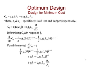
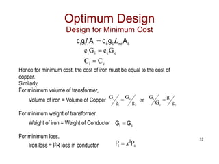
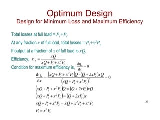
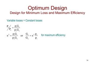
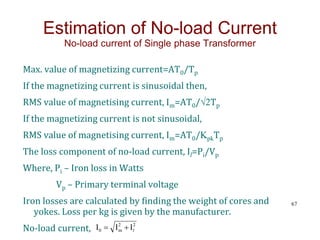
Design for Minimum Cost
c
i
m
c
i
m
A
A
B
2
2
A
A
B
r
)
2
(
r
B
2
A
A
B
2
A
A
r
m
c
i
m
c
i
β is the function of r alone [δ & Bm – Constant]
From (1) & (2),
29
M
A
&
M
A c
i
2
M
A
A i
c
](https://image.slidesharecdn.com/transformers-240614055703-04ffeaff/85/Transformers-design-and-coooling-methods-29-320.jpg)
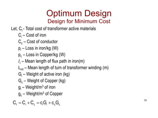
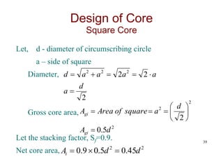
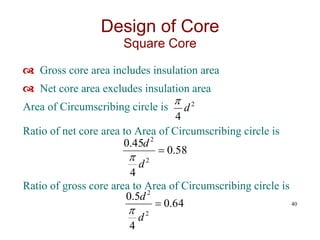
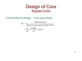
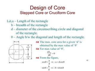
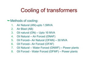

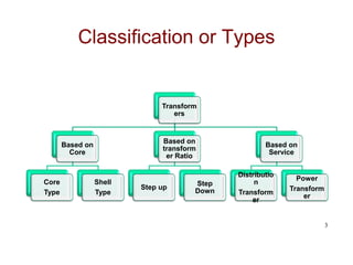
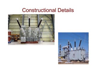
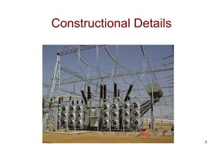
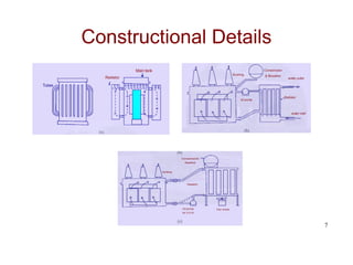
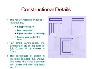
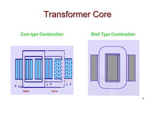
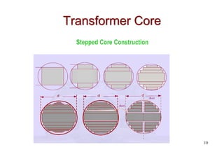
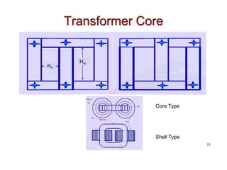
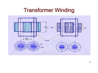
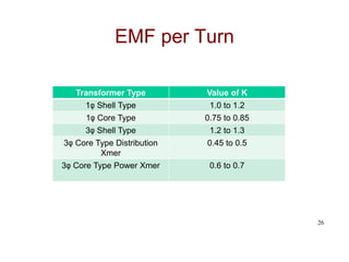
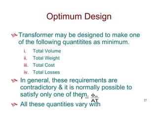
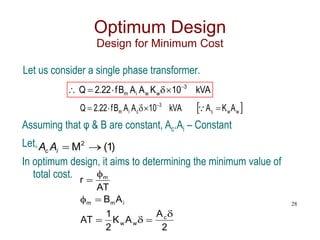
The document provides a comprehensive overview of transformer design, detailing its components, types, and classifications based on cores, service, and construction. It outlines the requirements for magnetic materials, types of windings, insulation methods, and construction techniques. Additionally, the document discusses optimum design principles, including minimizing cost, volume, weight, and losses, along with equations relating to transformer output and efficiency.