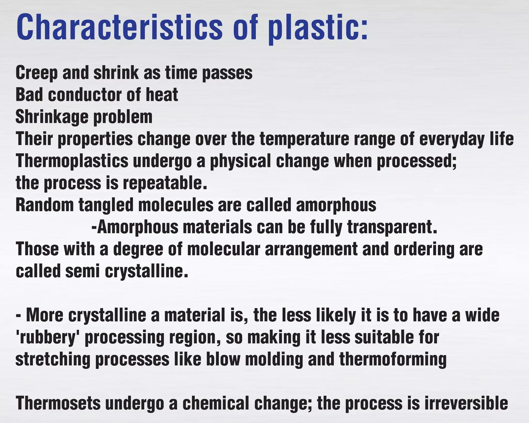
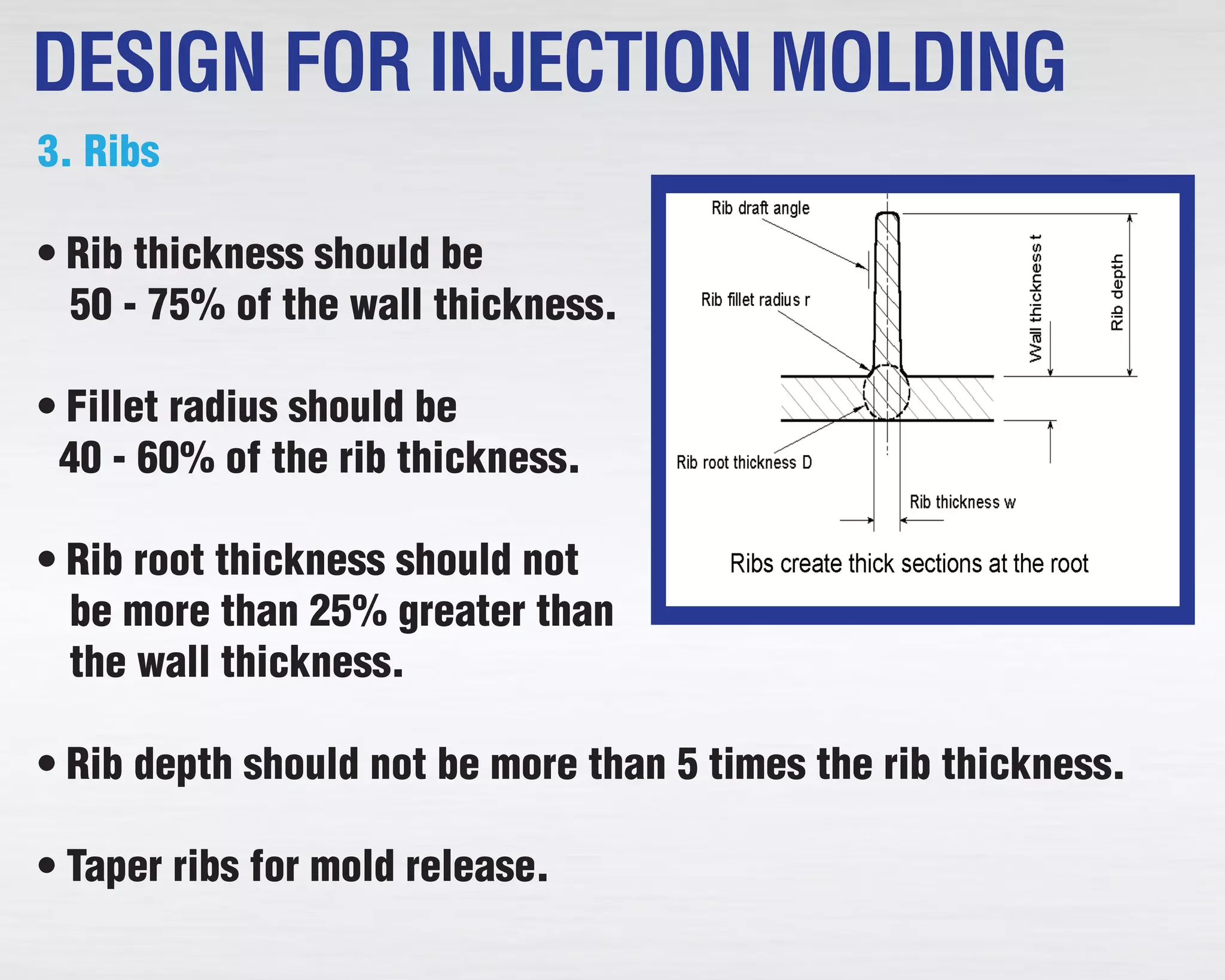
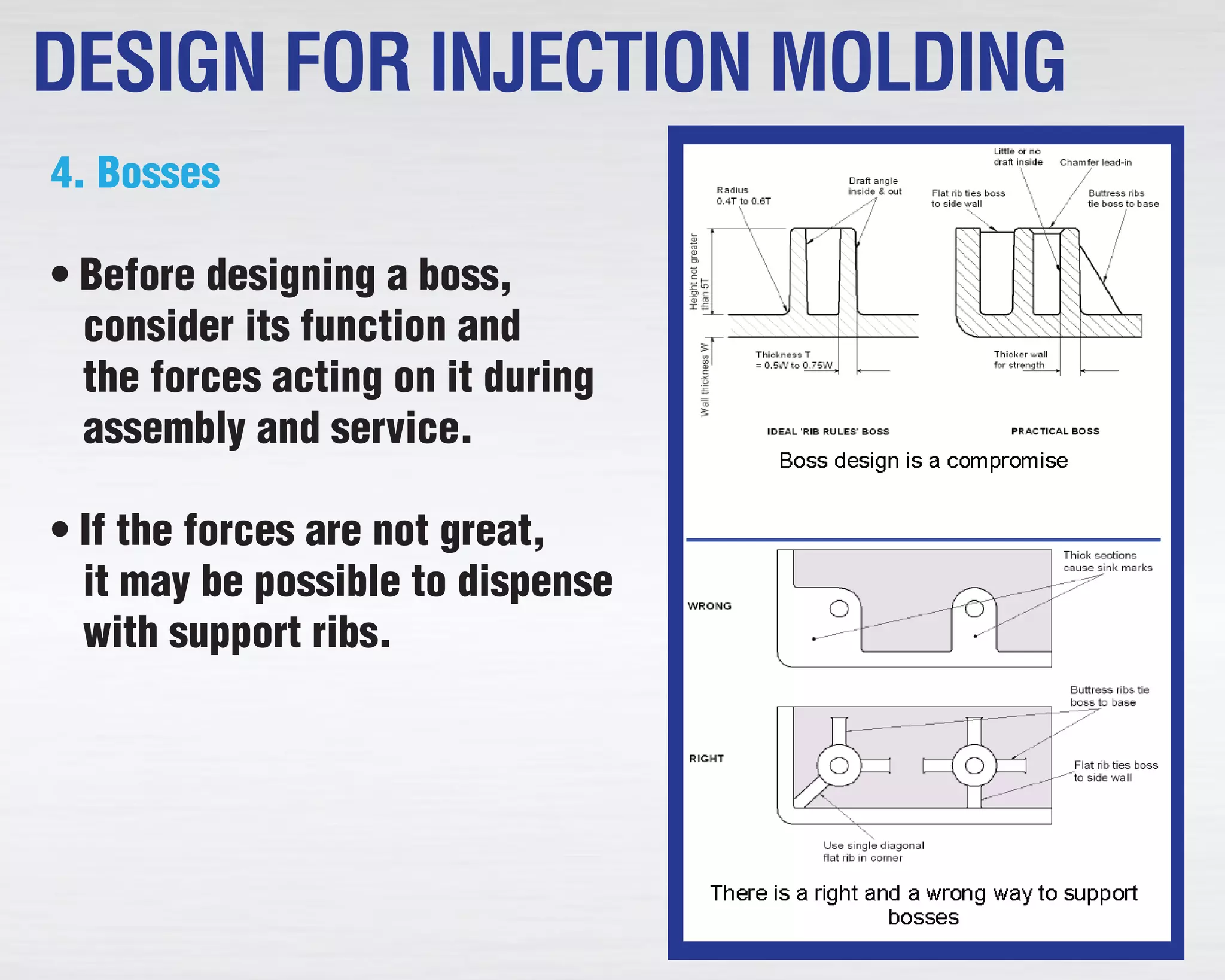
DESIGN FOR PLATICSDESIGN FOR PLATICS
A manufactured material produced using an extensive variety of
natural polymers for example, polyethylene, PVC, nylon, and so
on., that can be shaped into shape while delicate, and after
that set into an unbending or marginally flexible frame.
POLYMERISATION:- Polymerization is the way toward joining
together an expansive number of little particles to make a littler
number of expansive particles. The reactants (i.e. the little
particles from which the polymer is developed) are called
Monomers and results of the polymerization procedure are
called Polymers.
WHAT IS PLASTIC?
THERMOPLASTICS: Describes a substance which becomes flexible
when heated and hardens on cooling with no change in its
properties.
Examples:
Polyethylene: packaging, electrical insulation, milk and bottles,
packaging film
Polypropylene: carpet fibers, automotive bumpers, microwave
Polyvinyl chloride (PVC): electrical cables cover, credit cards.
Polystyrene: disposable spoons, forks, Styrofoam™
Acrylics (PMMA: polymethyl methacrylate): paints, fake fur
Polyamide (nylon): textiles and fabrics, gears, bushing and washers
PET (polyethylene terephthalate): bottles for acidic foods like juices
PTFE (polytetrafluoroethylene): non-stick coating, dental floss
TYPES OF THERMOPLASTICS
THERMOSETTING:-Thermosetting plastics are polymer materials
which are liquid or malleable at low temperatures, but which
change irreversibly to become hard at high temperatures.
Examples:
Polyurethanes: mattress, cushion, insulation, toys
Silicones: surgical gloves, oxygen masks in medical applications,
joint seals
Characteristics of plastic:
Creep and shrink as time passes
Bad conductor of heat
Shrinkage problem
Their properties change over the temperature range of everyday life
Thermoplastics undergo a physical change when processed;
the process is repeatable.
Random tangled molecules are called amorphous
-Amorphous materials can be fully transparent.
Those with a degree of molecular arrangement and ordering are
called semi crystalline.
- More crystalline a material is, the less likely it is to have a wide
'rubbery' processing region, so making it less suitable for
stretching processes like blow molding and thermoforming
Thermosets undergo a chemical change; the process is irreversible
DESIGN RULES FOR PLASTIC PARTS
• Allow for shrinkage subsequent to embellishment.
• Allow draft of at any rate ½ or 1°.
• Avoid under cut which requires centers or split depression form.
• Locate opening part in one plane.
• Locate openings at right point to part surface. Diagonal
openings include to shape cost.
• Design grille component parallel to the stream of plastic shape.
• UTS go from 2000 to15000 psi, must be checked.
• Locate gaps at right point to part surface.
• Arrange ejector stick so marks will happen on hid
surfaces.
• Design grille components parallel to the stream of plastic in form.
APPROCH TO DESIGN WITH PLASTIC
Each plastic material disfigures under outside load.
Metals particularly steels are great spring materials since they
have high quality and strength.
R = (1/2Sy Ey) = (1/2 Sy2/E)
Where Sy and Ey are stress and strain individually.
Plastics are unsatisfactory as spring material since they come to the
yield point at low estimation of stress and carry on viscoelastically.
A brief span of load is basic plan criteria for plastic
spring because of "Crawl" inclination of plastics.
VISCOELASTIC BEHAVIOR OF PLASTICS
The modulus of flexibility is not steady and relies on upon the rate
of stacking.
At steady stress, the strain will increment with time. This stream
impact called crawl.
A plastic material with a background marked by bolted up stresses
tends to open and achieves bring down estimation of stress.
1. Wall Thickness
• Keep wall thickness as
uniform as could reasonably be
expected.
• Use steady moves
amongst thick and thin
areas.
• Wall thickness must suit both
capacity and process.
• Wall thickness control range is:
- 0.75 mm to 3 mm for strengthened materials
- 0.5 mm to 5 mm for unreinforced materials
DESIGN FOR INJECTION MOLDING
2. Corners
• Avoid sharp inward corners.
• Internal radii ought to be at
minimum 0.5 and ideally 0.6
to 0.75 times the wall
thickness.
• Keep corner wall thickness
as close as conceivable to the ostensible divider thickness.
Preferably, outer radii ought to be equivalent to the inside radii
furthermore the wall thickness.
DESIGN FOR INJECTION MOLDING
3. Ribs
• Rib thickness ought to be
50 - 75% of the divider thickness.
• Filet sweep ought to be
40 - 60% of the rib thickness.
• Rib root thickness ought not
be over 25% more prominent than
the wall thickness.
• Rib profundity ought not be more than 5 times the rib thickness.
• Taper ribs for form discharge.
DESIGN FOR INJECTION MOLDING
4. Bosses
• Before designing a boss,
consider its function and
the forces acting on it during
assembly and service.
• If the forces are not great,
it may be possible to dispense
with support ribs.
DESIGN FOR INJECTION MOLDING
MOLDING OF PLASTICS
Pressure Molding:- The embellishment material, by and large
preheated, is first put in an open, warmed shape cavity. The
form is shut with a top compel or fitting part, weight is connected
to constrain the material into contact with all form regions, while
warm and weight are kept up until the
forming material has cured.
Exchange forming:- Transfer
embellishment is an assembling
procedure where throwing material is
constrained into a shape.
The material most generally utilized for
exchange trim is a thermoset
polymer.
Blow Molding
heated glass
3-piece mold
(a) The hollow piece of heated glass (parison)
is first created by a blow mold
(see text-book Fig 17.25)
(b) The mold is put together
(c) Plunger and hot air push the
glass up
(d) Hot air blows the glass out towards
the mold surface
(e) Mold comes apart, bottle is removed
heated glass
3-piece mold
(a) The hollow piece of heated glass (parison)
is first created by a blow mold
(see text-book Fig 17.25)
(b) The mold is put together
(c) Plunger and hot air push the
glass up
(d) Hot air blows the glass out towards
the mold surface
(e) Mold comes apart, bottle is removed
Injection Molding: designing injection molds
1. forming bearings - number of supplements/cams required
2. separating lines
3. separating planes - by amplifying the separating line outwards
4. gating plan - where to find the gate(s) ?
5. different pit form - settle relative places of the various parts
6. runners: stream of plastic into the cavity
7. sprue found:
8. useful parts of the form
- launch framework: to discharge the formed part
- frameworks to discharge the cemented runners
- arrangement bars: to keep all shape segments adjusted
Living Hinges
• Gate position is important.
• Flow must take place across
the hinge lines.
• Beware of hesitation effects,
weld lines, and over packing.
• Provide a separate hinge
cooling circuit.
• Flex the hinge immediately after ejection from the mold.
Bearings
• For metal shafts, the harder
and smoother the better.
• Keep within the PV limit.
• Use specific grade data for
K-factor and PV limit.
• Except for slow-running and
lightly loaded bearings, verify
the design by testing prototypes.
Gears
• Consider conditions of service
before selecting the material.
• Design for symmetry and avoid
excessive variations in
thickness.
• Make the center web
symmetrical and avoid ribs,
spokes and holes.
Design for Recycling
• Thermoplastics are preferable for reusing over cross-connected
thermosets.
• Prefer flexible materials that have an extensive variety of uses.
• Use perfect materials together to limit disassembling and
sorting.
• The material of produce ought to be set apart on every single
plastic part, utilizing standard images and shortened forms
• Eliminate the utilization of non-plastic parts
• Welded joints are useful for reusing however hard to disassemble
• Design for reusing, however not to the detriment of capacity or
benefit life
SPI RESIN IDENTIFICATION CODE
Contact Us
www.quality-mold.com
931-668-3876
QualityMoldShop,Inc.

Design for Plastics

  • 1.
  • 2.
    A manufactured materialproduced using an extensive variety of natural polymers for example, polyethylene, PVC, nylon, and so on., that can be shaped into shape while delicate, and after that set into an unbending or marginally flexible frame. POLYMERISATION:- Polymerization is the way toward joining together an expansive number of little particles to make a littler number of expansive particles. The reactants (i.e. the little particles from which the polymer is developed) are called Monomers and results of the polymerization procedure are called Polymers. WHAT IS PLASTIC?
  • 3.
    THERMOPLASTICS: Describes asubstance which becomes flexible when heated and hardens on cooling with no change in its properties. Examples: Polyethylene: packaging, electrical insulation, milk and bottles, packaging film Polypropylene: carpet fibers, automotive bumpers, microwave Polyvinyl chloride (PVC): electrical cables cover, credit cards. Polystyrene: disposable spoons, forks, Styrofoam™ Acrylics (PMMA: polymethyl methacrylate): paints, fake fur Polyamide (nylon): textiles and fabrics, gears, bushing and washers PET (polyethylene terephthalate): bottles for acidic foods like juices PTFE (polytetrafluoroethylene): non-stick coating, dental floss TYPES OF THERMOPLASTICS
  • 4.
    THERMOSETTING:-Thermosetting plastics arepolymer materials which are liquid or malleable at low temperatures, but which change irreversibly to become hard at high temperatures. Examples: Polyurethanes: mattress, cushion, insulation, toys Silicones: surgical gloves, oxygen masks in medical applications, joint seals
  • 5.
    Characteristics of plastic: Creepand shrink as time passes Bad conductor of heat Shrinkage problem Their properties change over the temperature range of everyday life Thermoplastics undergo a physical change when processed; the process is repeatable. Random tangled molecules are called amorphous -Amorphous materials can be fully transparent. Those with a degree of molecular arrangement and ordering are called semi crystalline. - More crystalline a material is, the less likely it is to have a wide 'rubbery' processing region, so making it less suitable for stretching processes like blow molding and thermoforming Thermosets undergo a chemical change; the process is irreversible
  • 6.
    DESIGN RULES FORPLASTIC PARTS • Allow for shrinkage subsequent to embellishment. • Allow draft of at any rate ½ or 1°. • Avoid under cut which requires centers or split depression form. • Locate opening part in one plane. • Locate openings at right point to part surface. Diagonal openings include to shape cost. • Design grille component parallel to the stream of plastic shape. • UTS go from 2000 to15000 psi, must be checked. • Locate gaps at right point to part surface. • Arrange ejector stick so marks will happen on hid surfaces. • Design grille components parallel to the stream of plastic in form.
  • 7.
    APPROCH TO DESIGNWITH PLASTIC Each plastic material disfigures under outside load. Metals particularly steels are great spring materials since they have high quality and strength. R = (1/2Sy Ey) = (1/2 Sy2/E) Where Sy and Ey are stress and strain individually. Plastics are unsatisfactory as spring material since they come to the yield point at low estimation of stress and carry on viscoelastically. A brief span of load is basic plan criteria for plastic spring because of "Crawl" inclination of plastics.
  • 8.
    VISCOELASTIC BEHAVIOR OFPLASTICS The modulus of flexibility is not steady and relies on upon the rate of stacking. At steady stress, the strain will increment with time. This stream impact called crawl. A plastic material with a background marked by bolted up stresses tends to open and achieves bring down estimation of stress.
  • 9.
    1. Wall Thickness •Keep wall thickness as uniform as could reasonably be expected. • Use steady moves amongst thick and thin areas. • Wall thickness must suit both capacity and process. • Wall thickness control range is: - 0.75 mm to 3 mm for strengthened materials - 0.5 mm to 5 mm for unreinforced materials DESIGN FOR INJECTION MOLDING
  • 10.
    2. Corners • Avoidsharp inward corners. • Internal radii ought to be at minimum 0.5 and ideally 0.6 to 0.75 times the wall thickness. • Keep corner wall thickness as close as conceivable to the ostensible divider thickness. Preferably, outer radii ought to be equivalent to the inside radii furthermore the wall thickness. DESIGN FOR INJECTION MOLDING
  • 11.
    3. Ribs • Ribthickness ought to be 50 - 75% of the divider thickness. • Filet sweep ought to be 40 - 60% of the rib thickness. • Rib root thickness ought not be over 25% more prominent than the wall thickness. • Rib profundity ought not be more than 5 times the rib thickness. • Taper ribs for form discharge. DESIGN FOR INJECTION MOLDING
  • 12.
    4. Bosses • Beforedesigning a boss, consider its function and the forces acting on it during assembly and service. • If the forces are not great, it may be possible to dispense with support ribs. DESIGN FOR INJECTION MOLDING
  • 13.
    MOLDING OF PLASTICS PressureMolding:- The embellishment material, by and large preheated, is first put in an open, warmed shape cavity. The form is shut with a top compel or fitting part, weight is connected to constrain the material into contact with all form regions, while warm and weight are kept up until the forming material has cured. Exchange forming:- Transfer embellishment is an assembling procedure where throwing material is constrained into a shape. The material most generally utilized for exchange trim is a thermoset polymer.
  • 14.
    Blow Molding heated glass 3-piecemold (a) The hollow piece of heated glass (parison) is first created by a blow mold (see text-book Fig 17.25) (b) The mold is put together (c) Plunger and hot air push the glass up (d) Hot air blows the glass out towards the mold surface (e) Mold comes apart, bottle is removed heated glass 3-piece mold (a) The hollow piece of heated glass (parison) is first created by a blow mold (see text-book Fig 17.25) (b) The mold is put together (c) Plunger and hot air push the glass up (d) Hot air blows the glass out towards the mold surface (e) Mold comes apart, bottle is removed
  • 15.
    Injection Molding: designinginjection molds 1. forming bearings - number of supplements/cams required 2. separating lines 3. separating planes - by amplifying the separating line outwards 4. gating plan - where to find the gate(s) ? 5. different pit form - settle relative places of the various parts 6. runners: stream of plastic into the cavity 7. sprue found: 8. useful parts of the form - launch framework: to discharge the formed part - frameworks to discharge the cemented runners - arrangement bars: to keep all shape segments adjusted
  • 16.
    Living Hinges • Gateposition is important. • Flow must take place across the hinge lines. • Beware of hesitation effects, weld lines, and over packing. • Provide a separate hinge cooling circuit. • Flex the hinge immediately after ejection from the mold.
  • 17.
    Bearings • For metalshafts, the harder and smoother the better. • Keep within the PV limit. • Use specific grade data for K-factor and PV limit. • Except for slow-running and lightly loaded bearings, verify the design by testing prototypes.
  • 18.
    Gears • Consider conditionsof service before selecting the material. • Design for symmetry and avoid excessive variations in thickness. • Make the center web symmetrical and avoid ribs, spokes and holes.
  • 19.
    Design for Recycling •Thermoplastics are preferable for reusing over cross-connected thermosets. • Prefer flexible materials that have an extensive variety of uses. • Use perfect materials together to limit disassembling and sorting. • The material of produce ought to be set apart on every single plastic part, utilizing standard images and shortened forms • Eliminate the utilization of non-plastic parts • Welded joints are useful for reusing however hard to disassemble • Design for reusing, however not to the detriment of capacity or benefit life
  • 20.
  • 21.