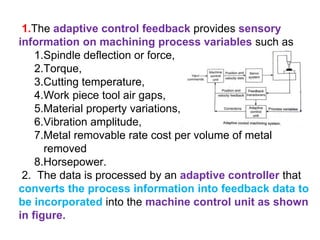
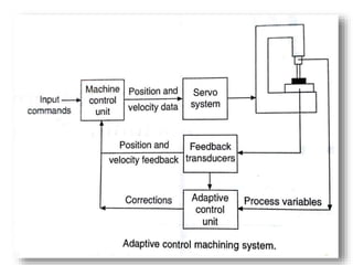
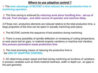
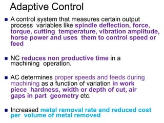
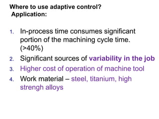
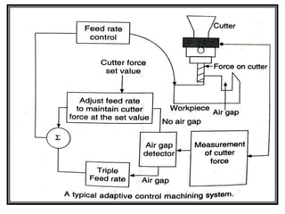
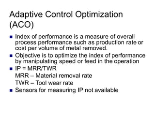
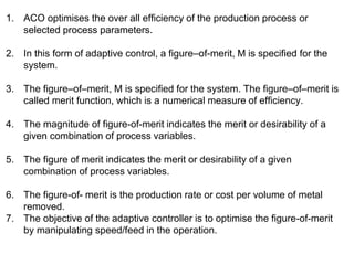
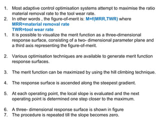
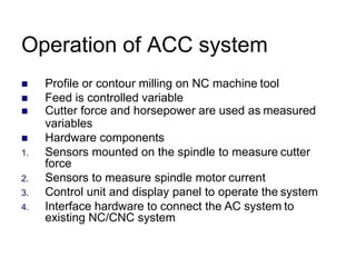
Adaptive Control Machining systems, Introduction, Where to use adaptive control ?.Adaptive Control, Elements of an adaptive control machining system, Types of Adaptive controls, Benefits of AC
3. Introduction
1. Adaptive control machining has been developed to
optimize machining characteristics
2. The AC machining is an evolutionary out growth of
numerical control.
3. It is a control system that measures certain output
process variables and uses these to control speed and
/ or feed.
4. Some of the process variables that have been used in
adaptive control machining systems include spindle
deflection or force, torque , cutting temperature,
vibration amplitude , metal removable rate cost per
volume of metal removed and horse power.
4. 1.The adaptive control feedback provides sensory
information on machining process variables such as
1.Spindle deflection or force,
2.Torque,
3.Cutting temperature,
4.Work piece tool air gaps,
5.Material property variations,
6.Vibration amplitude,
7.Metal removable rate cost per volume of metal
removed
8.Horsepower.
2. The data is processed by an adaptive controller that
converts the process information into feedback data to
be incorporated into the machine control unit as shown
in figure.
5.
6. 1. The main advantage of NC/CNC is that reduces the non-productive time in
machining operation.
2. This time saving is achieved by reducing work piece handling time , set-up of
the job, Tool changes , and other source of operator and machine delay.
3.If these non- productive elements are reduced relative to the total production time, a
large proportion of the time can be spent in actually machining work piece.
4. The NC/CNC controls the sequence of tool positions during machining.
5. There is every possibility of spindle deflection or increasing of cutting temperature,
or work piece tool air gaps, or material property variations or machine tool vibration,
this process parameters waste production time
5. The most promising means of reducing the productive time is
the USE OF ADAPTIVE CONTROL
6. AC determines proper speed and feed during machining as functions of variations
in process variables such as Work-material hardness ,width or depth cut , air gaps in
the part geometry
Where to use adaptive control ?
7. Adaptive Control
A control system that measures certain output
process variables like spindle deflection, force,
torque, cutting temperature, vibration amplitude,
horse power and uses them to control speed or
feed
NC reduces non productive time in a
machining operation.
AC determines proper speeds and feeds during
machining as a function of variation in work
piece hardness, width or depth of cut, air
gaps in part geometry etc.
Increased metal removal rate and reduced cost
per volume of metal removed
8. Where to use adaptive control?
Application:
1. In-process time consumes significant
portion of the machining cycle time.
(>40%)
2. Significant sources of variability in the job
3. Higher cost of operation of machine tool
4. Work material – steel, titanium, high
strengh alloys
9. Sources of variability in
machining
1. Variable depth/width of cut
2. Variable workpiece hardness and
variable machinability
3. Variable workpiece rigidity
4. Toolwear
5. Air gaps during cutting
10.
11. Elements of an adaptive control machining system.
1. The machining process is affected by many process variables.
2. In addition to cutting to cutting forces and position and velocity
feedback, the AC monitors vibrations, cutting temperature and spindle
horse power
3. In order to fulfill these requirements , AC requires sophisticated
transducers and sensor.
4. Strain gauges are used to sense the cutting force, tool deflection and
torque.
5. Typical strain gauges is shown in figure which are bonded to the tool
holding structure so that both horizontal and vertical forces cause
corresponding tool stains, which can be measured
12.
13. 1. Motor house power input is determined by measuring motor current. The
cutting temperature is measured by using the thermocouple principle (Figure
below).
The e.m.f. in a thermo-electric circuit is ascribed to the following tow
phenomena:
Peltier effect: This governs the e.m.f. resulting solely from the contact of two
different metals and magnitude varying with the temperature of this contact.
Thomson effect: This is the e.m.f. resulting from the temperature gradient
along the single sire and is less predominant.
14. 1. Tool vibration is determined by mounting an accelerometer on the spindle
housing (Figure below).
The air gap can be sensed by a tool force sensor. For an air gap, the tool
force sensor indicates zero force reading.
15. 1. Figure represents a typical adaptive control machining system. It
operates on the principle of maintaining a constant cutter force during
the machining operation.
2. When the force increases due to increased work piece harness or
the depth or width of cut, the feed rate is reduced to compensate for
this.
3. When the force decreases owing to decreases in the forgoing
variables or air gaps in the part, the feed rate is increased to
maximize the rate of the metal removed.
16. 1. Figure shows the presence of an air gap over-ride feature which monitor
the cutter force and determines if the cutter is moving through air or
through metal.
2. This is usually sensed by means of a low threshold value of cutter force. If
the actual cutter force is below this threshold level, the controller assumes
that the cutter is passing through an air gap, the feed reverts to the cutter
force mode of control.
3. More than one process variable may be measured in an AC machining
system.
4. Originally, attempts were made to employ three measured signals in the
Bendix system: temperature, torque, and vibration.
5. The Mactech system has used both cutter load and horsepower generated
at the machine motor.
6. The purpose of the power sensor is to protect the motor from the overload
when the metal removal rate is constrained by spindle horsepower rather
than spindle force.
17. Types of Adaptive controls
1. Adaptive control Optimisation (ACO)
2. Adaptive control Constraint (ACC)
18. Adaptive Control Optimization
(ACO)
Index of performance is a measure of overall
process performance such as production rate or
cost per volume of metal removed.
Objective is to optimize the index of performance
by manipulating speed or feed in the operation
IP = MRR/TWR
MRR – Material removal rate
TWR – Tool wear rate
Sensors for measuring IP not available
19. 1. ACO optimises the over all efficiency of the production process or
selected process parameters.
2. In this form of adaptive control, a figure–of-merit, M is specified for the
system.
3. The figure–of–merit, M is specified for the system. The figure–of–merit is
called merit function, which is a numerical measure of efficiency.
4. The magnitude of figure-of-merit indicates the merit or desirability of a
given combination of process variables.
5. The figure of merit indicates the merit or desirability of a given
combination of process variables.
6. The figure-of- merit is the production rate or cost per volume of metal
removed.
7. The objective of the adaptive controller is to optimise the figure-of-merit
by manipulating speed/feed in the operation.
20. 1. Most adaptive control optimisation systems attempt to maximise the ratio
material removal rate to the tool wear rate.
2. In other words , the figure-of-merit is: M=f(MRR,TWR) where
MRR=material removal rate
TWR=tool wear rate
1. It is possible to visualize the merit function as a three-dimensional
response surface, consisting of a two- dimensional parameter plane and
a third axis representing the figure-of-merit.
2. Various optimisation techniques are available to generate merit function
response surfaces.
3. The merit function can be maximized by using the hill climbing technique.
4. The response surface is ascended along the steepest gradient.
5. At each operating point, the local slope is evaluated and the next
operating point is determined one step closer to the maximum.
6. A three- dimensional response surface is shown in figure
7. The procedure is repeated till the slope becomes zero.
21.
22. Adaptive control Constraint (ACC)
Nearly all AC systems is of this type
Less sophisticated and less expensive
than research ACO systems
Objective is to manipulate speed or feed
so that measured process variables are
maintained at or below their constraint limit
values.
23. Adaptive control constraint (ACC)
1. The objective of the controller is to manipulate speed/feed to maintain
the measured variables at or below their constraint limit values.
2. Constraints define the permissible range of operation.
3. The constraints violation detection logic determines whether the process
variable exceeded the pre- defined limit or not.
4. If constraint violation has occurred, the ACU logic sub- system
increments or decrements the value of the ACU output such that the
process variable is within the pre- defined limits.
5. The flowchart of a constraint violation detection system is shown in
figure.
6. If dangerous conditions are found the constraint violation detection
system stops the machining operations and shuts down the machine
tool.
24.
25. Operation of ACC system
Profile or contour milling on NC machine tool
Feed is controlled variable
Cutter force and horsepower are used as measured
variables
Hardware components
1. Sensors mounted on the spindle to measure cutter
force
2. Sensors to measure spindle motor current
3. Control unit and display panel to operate the system
4. Interface hardware to connect the AC system to
existing NC/CNC system
27. Benefits of AC
1. Increased production rate
2. Increased tool life
3. Greater part protection
4. Increases machine life
5. Less operator intervention
6. Easier part programming