Downloaded 461 times


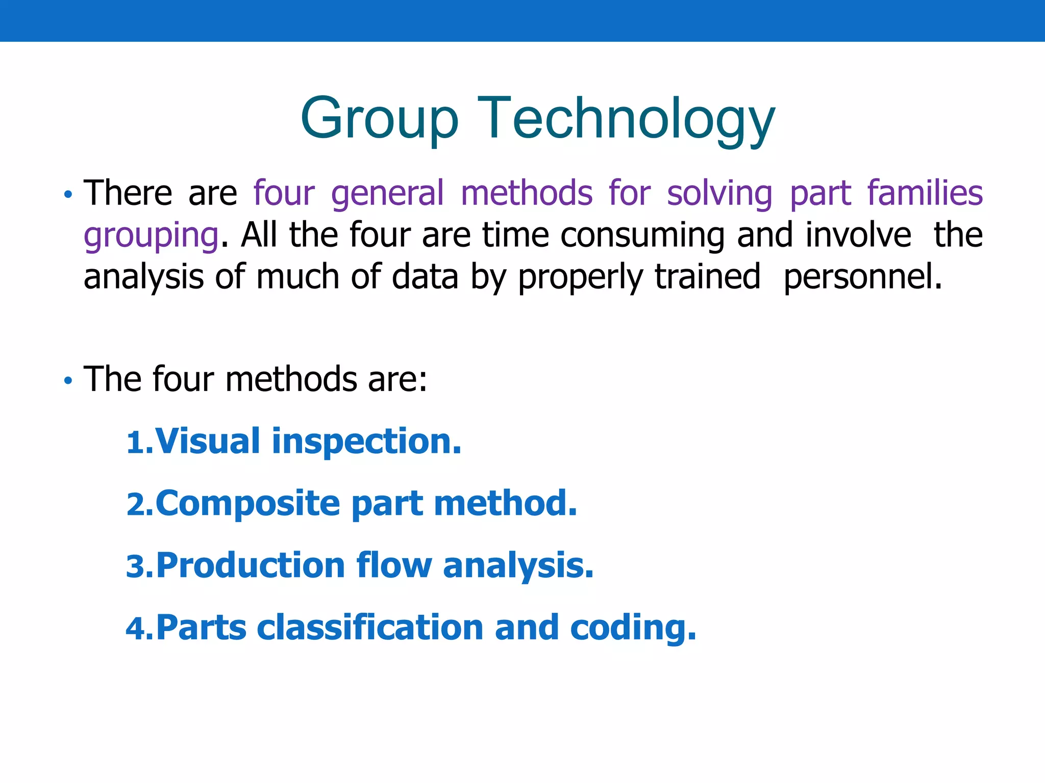


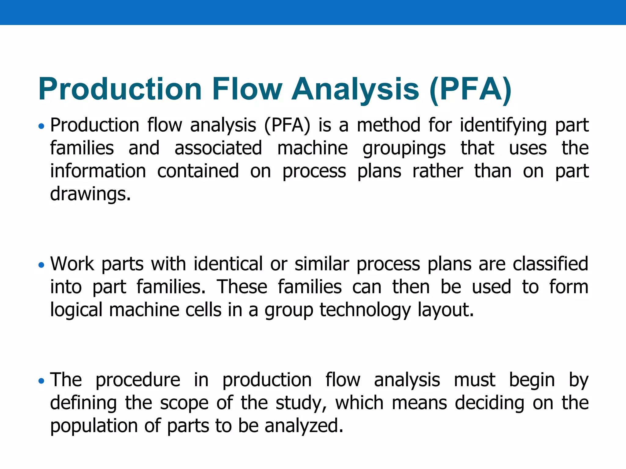
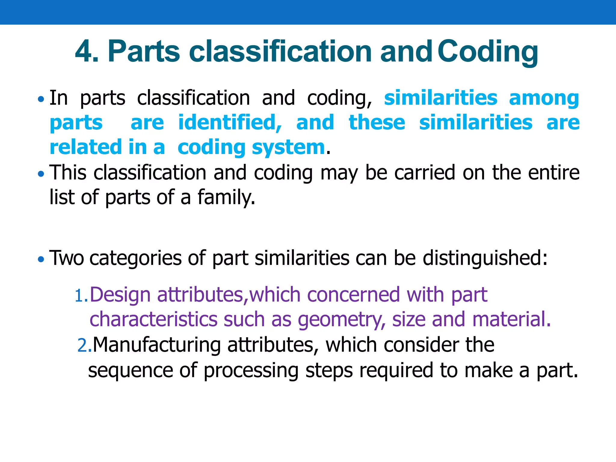


Group technology (GT) is a manufacturing philosophy that groups similar parts to enhance integration between design and manufacturing. Implementing GT involves identifying part families and rearranging machines into cells, which can be time-consuming and costly. Various methods for grouping parts include visual inspection, composite part method, production flow analysis, and parts classification and coding, each with their own advantages for standardization and efficiency in manufacturing processes.