Downloaded 657 times


![20
MACHINING TIME
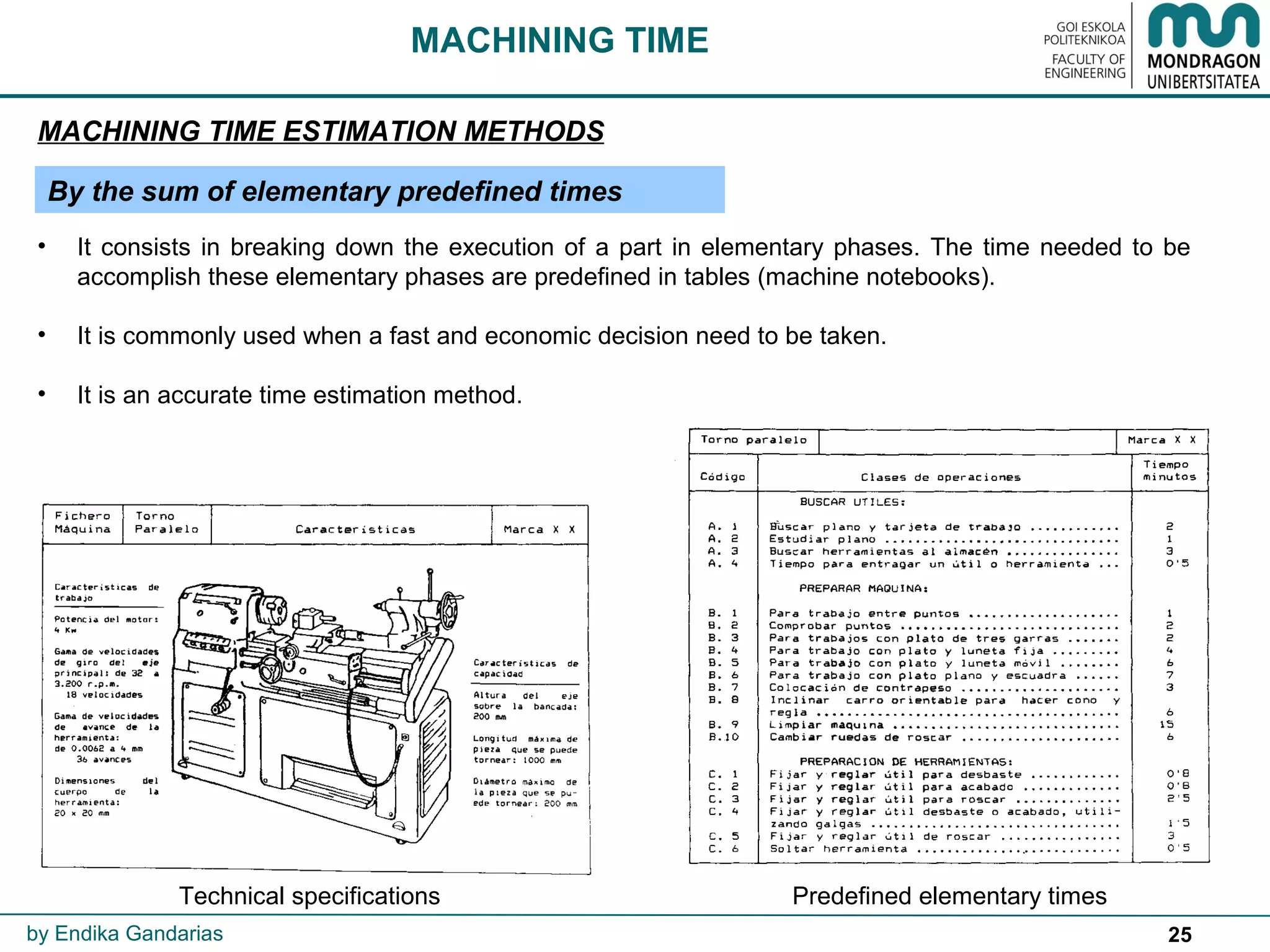
MACHINING TIME ESTIMATION METHODS
by Endika Gandarias
• The TOTAL MACHINING TIME (TT) calculus is very important to determine:
• Manufacturing costs: Machine rate [€/h] * TT [h]
• Machine work loads
• Personnel needs.
• Delivery time
• The cutting time (TCUTTING) is the only one that can be accurately calculated.
Rest of the times need to be estimated.
• Most commonly used TIME ESTIMATION methods are:
1. By estimation.
2. By comparison.
3. By timing.
4. By the sum of elementary predefined times.](https://image.slidesharecdn.com/6machiningtimeandcosts-170204222154/75/Machining-time-and-costs-20-2048.jpg)


The document details machining cost and time estimation methods essential for manufacturing. It outlines the relationship between cost, material, design, and process, emphasizing the need for accurate estimations to maintain competitiveness. Various estimation techniques, including analytical and parametric methods, as well as specific cutting time calculations, are discussed to facilitate efficient manufacturing practices.