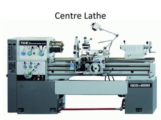
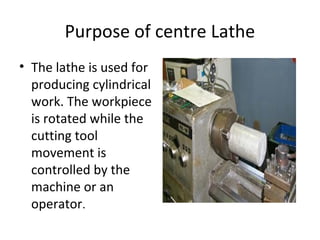
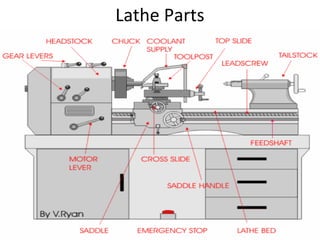
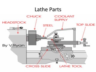
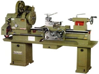
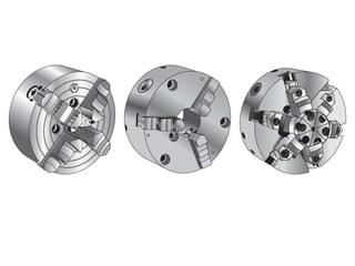
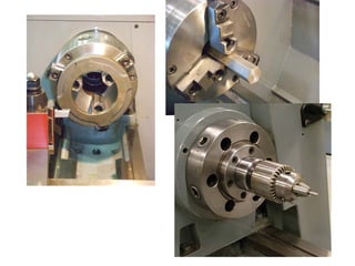
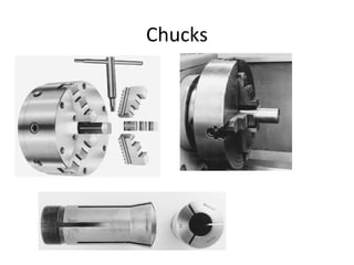
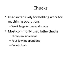
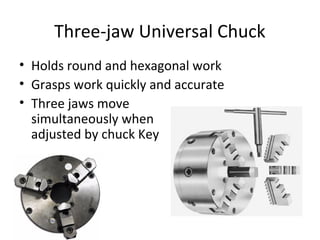
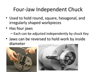
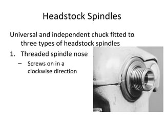
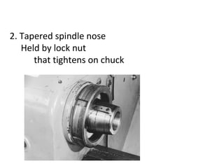
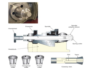
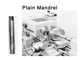
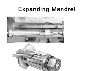
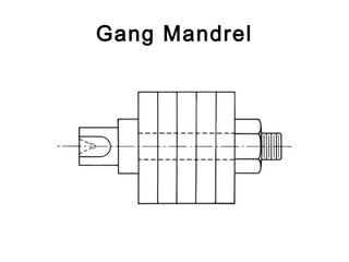
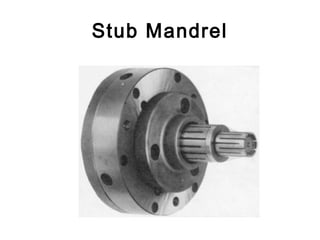
This document provides information about mechanical engineering and the centre lathe. It discusses the main parts and functions of the lathe, including the headstock, bed, carriage, cross-slide, apron, tailstock, tool post, and quick-change gearbox. It also covers lathe safety, types of lathes, cutting speeds, lathe accessories such as centers, chucks, faceplates, and work holding methods. The objectives are to identify lathe parts and their purposes, discuss safety procedures, calculate cutting speeds, and describe various lathe accessories.
Producing hole is one of the most common machining operation on a machining center.
Machining center have many hole making cycles such as Spot Drilling, Reaming, Deep Hole drilling, Peck drilling etc.
in this Ppt all canned cycle are explained i;e G70 G71 G72 G73 G75 G76 G81
Unit 2 Machinability, Cutting Fluids, Tool Life & Wear, Tool MaterialsMechbytes
Concept of machinability, machinability index, factors affecting machinability
Different mechanism of tool wear types of tool wear (crater, flank etc.), Measurement and control of tool wear
Concept of tool life, Taylor's tool life equation (including modified version)
Different tool materials and their applications including effect of tool coating
Introduction to economics of machining
Cutting fluids: types, properties, selection and application methods
Surface roughness metrology deals with basic terminology of surface,surface roughness indication methods,analysis of surface traces, measurement methods,surface roughness measuring instruments such as Stylus Probe Instrument, Profilometer, Tomlinson Surface Meter ,The Taylor-Hobson Talysurf etc.This is very useful for diploma,degree engineering students of mechanical,production,automobile branch
PPT IS IMPORTANT FOR FE PUNE UNIVERSITY STUDENTS FOR SUBJECT BME. DETAILED DESCRIPTION IS GIVEN ABOUT LATHE MACHINE, DRILLING MACHINE AND GRINDING MACHINE
this file is about the types of dies and also its manufacturing procedure.this is important for the industry and for the industrial and manufacturing engineering..are of this field is manufacturing engineering and die designalso for the blanking dies and punches
AI and Machine Learning Demystified by Carol Smith at Midwest UX 2017Carol Smith
What is machine learning? Is UX relevant in the age of artificial intelligence (AI)? How can I take advantage of cognitive computing? Get answers to these questions and learn about the implications for your work in this session. Carol will help you understand at a basic level how these systems are built and what is required to get insights from them. Carol will present examples of how machine learning is already being used and explore the ethical challenges inherent in creating AI. You will walk away with an awareness of the weaknesses of AI and the knowledge of how these systems work.
IN THIS PRESENTATION CONSIST ON LATHE AND ITS TYPES EXPLAIN SHORT &
SWEET WITH GRAPHICAL REPRESENTATION
Note : PART-A CONTINUOUS..... Remaining Unit Update soon ...WIsh you Happy Learning.....
Centre lathe, constructional features, specification, operations – taper turning methods, thread
cutting methods, special attachments, machining time and power estimation. Capstan and turret
lathes- tool layout – automatic lathes: semi automatic – single spindle : Swiss type, automatic
screw type – multi spindle:
The Indian economy is classified into different sectors to simplify the analysis and understanding of economic activities. For Class 10, it's essential to grasp the sectors of the Indian economy, understand their characteristics, and recognize their importance. This guide will provide detailed notes on the Sectors of the Indian Economy Class 10, using specific long-tail keywords to enhance comprehension.
For more information, visit-www.vavaclasses.com
2024.06.01 Introducing a competency framework for languag learning materials ...Sandy Millin
http://sandymillin.wordpress.com/iateflwebinar2024
Published classroom materials form the basis of syllabuses, drive teacher professional development, and have a potentially huge influence on learners, teachers and education systems. All teachers also create their own materials, whether a few sentences on a blackboard, a highly-structured fully-realised online course, or anything in between. Despite this, the knowledge and skills needed to create effective language learning materials are rarely part of teacher training, and are mostly learnt by trial and error.
Knowledge and skills frameworks, generally called competency frameworks, for ELT teachers, trainers and managers have existed for a few years now. However, until I created one for my MA dissertation, there wasn’t one drawing together what we need to know and do to be able to effectively produce language learning materials.
This webinar will introduce you to my framework, highlighting the key competencies I identified from my research. It will also show how anybody involved in language teaching (any language, not just English!), teacher training, managing schools or developing language learning materials can benefit from using the framework.
Ethnobotany and Ethnopharmacology:
Ethnobotany in herbal drug evaluation,
Impact of Ethnobotany in traditional medicine,
New development in herbals,
Bio-prospecting tools for drug discovery,
Role of Ethnopharmacology in drug evaluation,
Reverse Pharmacology.
How to Create Map Views in the Odoo 17 ERPCeline George
The map views are useful for providing a geographical representation of data. They allow users to visualize and analyze the data in a more intuitive manner.
Welcome to TechSoup New Member Orientation and Q&A (May 2024).pdfTechSoup
In this webinar you will learn how your organization can access TechSoup's wide variety of product discount and donation programs. From hardware to software, we'll give you a tour of the tools available to help your nonprofit with productivity, collaboration, financial management, donor tracking, security, and more.
How to Make a Field invisible in Odoo 17Celine George
It is possible to hide or invisible some fields in odoo. Commonly using “invisible” attribute in the field definition to invisible the fields. This slide will show how to make a field invisible in odoo 17.
How to Split Bills in the Odoo 17 POS ModuleCeline George
Bills have a main role in point of sale procedure. It will help to track sales, handling payments and giving receipts to customers. Bill splitting also has an important role in POS. For example, If some friends come together for dinner and if they want to divide the bill then it is possible by POS bill splitting. This slide will show how to split bills in odoo 17 POS.
This is a presentation by Dada Robert in a Your Skill Boost masterclass organised by the Excellence Foundation for South Sudan (EFSS) on Saturday, the 25th and Sunday, the 26th of May 2024.
He discussed the concept of quality improvement, emphasizing its applicability to various aspects of life, including personal, project, and program improvements. He defined quality as doing the right thing at the right time in the right way to achieve the best possible results and discussed the concept of the "gap" between what we know and what we do, and how this gap represents the areas we need to improve. He explained the scientific approach to quality improvement, which involves systematic performance analysis, testing and learning, and implementing change ideas. He also highlighted the importance of client focus and a team approach to quality improvement.
The French Revolution, which began in 1789, was a period of radical social and political upheaval in France. It marked the decline of absolute monarchies, the rise of secular and democratic republics, and the eventual rise of Napoleon Bonaparte. This revolutionary period is crucial in understanding the transition from feudalism to modernity in Europe.
For more information, visit-www.vavaclasses.com
3. objectives
• Main purpose of the centre lathe
• Safety precautions on the centre lathe
• Types of Lathe
• Identify main parts of the centre lathe
• State the purpose of each main parts
• Method of Holding work
• Method of cutting tapers
• Cutting speed on the Lathe
4. Purpose of centre Lathe
• The lathe is used for
producing cylindrical
work. The workpiece
is rotated while the
cutting tool
movement is
controlled by the
machine or an
operator.
5. Centre Lathe
• lathes may be operated directly by
people (manual lathes) or computer
controlled lathes (CNC machines) that
have been programmed to carry out a
particular task.
6. Safety Precautions
• Always wear approved safety glasses
• Rollup sleeves, remove tie and tuck in loose
clothing
• Never operate machine if safety guards
removed
• Stop lathe before measure work or clean, oil
or adjust machine
• Always remove chuck key after use
• Always remove chips with brush
7. Types of Lathe
Engine Lathe
The most common form
of lathe, motor driven
and comes in large
variety of sizes and
shapes. Not production
lathe, found in school
shops.
.
8. Types of Lathe
Bench Lathe
A bench top
model usually of
low power used
to make
precision machine
small work pieces.
9. Types of Lathe
Tracer Lathe
a lathe that has
the ability to
follow a template
to copy a shape
or contour
10. Types of Lathe
Automatic Lathe
A lathe in which the
work piece is
automatically fed
and removed
without use of an
operator.
11. Types of Lathe
–Turret Lathe
lathe which have
multiple tools
mounted on turret
either attached to the
tailstock or the cross-
slide, which allows for
quick changes in
tooling and cutting
operations.
12. Types of lathe
Computer Controlled
Lathe
–A highly automated
lathe, where both
cutting, loading, tool
changing, and part
unloading are
automatically
controlled by
computer coding.
17. Headstock
• Clamped on left-hand end of bed
• Headstock spindle
–Hollow cylindrical shaft supported by
bearings
• Provides drive through gears to work-
holding devices
–Live center, faceplate, or chuck fitted to
spindle nose to hold and drive work
• Driven by stepped pulley or transmission
gears
19. Lathe Bed
• Heavy, rugged casting
• Made to support working parts of lathe
• On top section are machined ways
–Guide and align major parts of lathe
21. Carriage
• Used to move cutting tool along lathe bed
• Consists of three main parts
–Saddle
• H-shaped casting mounted on top of
lathe ways, provides means of
mounting cross-slide and apron
–Cross-slide
–Apron
23. Cross-slide
• Mounted on top of saddle
• Provides manual or automatic cross
movement for cutting tool
• Compound rest (fitted on top of cross-
slide)
–Used to support cutting tool
–Swiveled to any angle for taper-turning
–Has graduated collar that ensure
accurate cutting-tool settings (.001 in.)
(also cross-slide)
25. Apron
• Fastened to saddle
• Houses gears and mechanism required to
move carriage or cross-slide automatically
• Locking-off lever inside apron prevents
engaging split-nut lever and automatic
feed lever at same time
• Apron handwheel turned manually to
move carriage along lathe bed
27. Tailstock
• Upper and lower tailstock castings
• Adjusted for taper or parallel turning by
two screws set in base
• Tailstock clamp locks tailstock in any
position along bed of lathe
• Tailstock spindle has internal taper to
receive dead center
–Provides support for right-hand end of
work
28. Tool post
• There are three main types of tool post used
for holding lathe cutting tools:
Ring and rocker
Four-way turret
Quick -change
29. Ring and Rocker
• With this type, tools are
quickly adjusted at
centre height by moving
the rocker, which beds
on the loose ring
around the main post.
30. Four-way tool post
• It has four ways, or
sides, which allow four
cutting tools to be held
at the same time.
31. Quick-change
• No need for packing.
The adjustment is done
by means of screw.
There are separate tool
holders that fit the four
faces of the main block
and are easily removed
and returned to exactly
the same setting.
32. Compound slide/ Top slide
• It is fixed on top of the
cross-slide, and can be
turned (set) to any
desired angle. The
compound slide is
useful for turning and
boring short tapers and
chamfers.
34. Quick-Change Gearbox
• Contains number of different-size gears
• Provides feed rod and lead-screw with
various speeds for turning and thread-
cutting operations
– Feed rod advances carriage when automatic
feed lever engaged
– Lead screw advances the carriage for thread-
cutting operations when split-nut lever
engaged
35. Quiz points
• Produce cylindrical work
• Type of lathe Programme to
carry out task
• Use to tighten the chuck
• Types of lathe use in school
workshops
• Use to make precision work
and small work pieces.
• lathe which have multiple
tools
• Tool post that doesn’t need
packing
• Use to produce short tapers
• Made to support working
parts of lathe
• Found at the left side of the
bed
• Found at the right side of
the bed
• Hold four tools at the same
time
• Used to move cutting tool
along lathe bed
• Parts of the machine use
when facing off
36. Lathe Size and Capacity
• Designated by largest work diameter that can
be swung over lathe ways and generally the
maximum distance between centers
41. Cutting speed
• Cutting speed for turning is the speed at
which the work rotates. This is also known as
surface speed
42. 47-42
Cutting Speed
• Rate at which point on work circumference
travels past cutting tool
• expressed in meters per minute (m/min)
• Important to use correct speed for material
–Too high: cutting-tool breaks down
rapidly
–Too low: time lost, low production rates
44. • The hardness of the cutting tool material has a
great deal to do with the recommended cutting
speed. The harder the cutting tool material, the
faster the cutting speed. The softer the cutting
tool material, the slower the recommended
cutting speed
45. • The depth of the cut and the feed rate will also
affect the cutting speed, but not to as great an
extent as the work hardness
46. Factors that Determine cutting speed
• The material being cut
• The rigidity and condition of the machine
• The material of which the tool is made from
• The depth of cut and the feed rate
• Availability of coolant (cutting fluid)
47. Setting Speeds on a Lathe
• Speeds measured in revolutions per minute
– Changed by stepped pulleys or gear levers
• Belt-driven lathe
– Various speeds obtained by changing flat belt
and back gear drive
• Geared-head lathe
– Speeds changed by moving speed levers into
proper positions according to r/min chart
fastened to headstock
Safety Note!! NEVER change speeds
when lathe is running.
48. 48
Setting Speeds on a
Lathe• Speeds measured in revolutions per
minute
– Changed by stepped pulleys or gear
levers
• Belt-driven lathe
– Various speeds obtained by changing flat
belt and back gear drive
• Geared-head lathe
– Speeds changed by moving speed levers
into proper positions according to r/min
chart fastened to headstock
49. Lathe Cutting Speeds
Material being cut Cutting speed (metres/minute
Mild steel 20 to 28
Cast iron 18 to 25
High carbon steel 12 to 18
Brass 45 to 90
Bronze 15 to 21
Aluminium Upto 300
47-49
50. 47-50
Calculating Lathe cutting speed
• Given in metres per minute
• spindle speed of machine (N) and diameter
of work must be known
• S (m/min)= πDN/1000
• Where π= 22/7 or 3.142
• D= diameter of material
• N= Spindle speed(rev/min)
51. Calculating Lathe Spindle speed
(rev/min)
D
xS1000
rev/min
π
=
S (m/min)= cutting speed
Where π= 22/7 or 3.142
D= diameter of material
N= Spindle speed(rev/min
52. Examples
• Calculate rev/min required to rough-turn
150mm diameter piece of machine steel (CS
90)
• Find the cutting speed of a 50mm diameter
bar being turned with a spindle of 178
rev/min.
53. Exercise
• Calculate the spindle speed required to turn
200mm diameter piece of high speed steel, if the
cutting speed is 28 m/min.
• Find the cutting speed of a 15mm diameter bar
being turned with a spindle of 955 rev/min.
• Determine the lathe speed to cut a 40mm
diameter at 30 m/min
47-53
54. Class work
1. What is cutting speed for turning?
2. State the unit for cutting speed.
3. Which of the following materials have the
highest cutting speed.
1. Brass 2. Bronze 3. mild steel.
Give reasons for your choice.
4. List four factors that determine the cutting
speed. Explain any two factors.
Continue on next slide.
56. Objectives
• Explain what is lathe accessories
• Identify and explain lathe accessories
used in the metal work shop.
57. Lathe Accessories
• What is Lathe accessories?
• Equipment or tools used on the lathe to
assist in performing an operation.
58. Lathe Accessories
• Divided into two categories
– Work-holding, -supporting, and –driving
devices
• Lathe centers, chucks, faceplates
• Mandrels, steady and follower rests
• Lathe dogs, drive plates
– Cutting-tool-holding devices
• Straight and offset toolholders
• Threading toolholders, boring bars
• Turret-type toolposts
59. Lathe Centers
• Work to be turned between centers must
have center hole drilled in each end
• Support during cutting
• Most common have
solid Morse taper shank
60º centers, steel with carbide tips
• Care to adjust and lubricate occasionally
61. Type of Lathe Centres
• Lathe centres is used as a support at the end
of a work. It is usually made from carbon tool
steel. There are three (3) main types of Lathe
centres:
• Live centre (Revolving centre)
• Dead centre
• Half centre
62. Live centre (Revolving Centre)
• It is constructed so that the 60° center runs in its
own bearings .
• The live centre fits in the spindle (headstock)and
rotates with the spindle.
• Used when turning between centres
64. Dead centre
• Fits in the tailstock spindle, remains stationary
while the work rotates on its point
65. Half Centre
• A centre that is cut away almost to its point. It
is often used in the tailstock for facing up to or
for turning close to the end of the work.
69. Chucks
• Used extensively for holding work for
machining operations
– Work large or unusual shape
• Most commonly used lathe chucks
– Three-jaw universal
– Four-jaw independent
– Collet chuck
70. Three-jaw Universal Chuck
• Holds round and hexagonal work
• Grasps work quickly and accurate
• Three jaws move
simultaneously when
adjusted by chuck Key
71. Four-Jaw Independent Chuck
• Used to hold round, square, hexagonal, and
irregularly shaped workpieces
• Has four jaws
– Each can be adjusted independently by chuck Key
• Jaws can be reversed to hold work by inside
diameter
72. Headstock Spindles
Universal and independent chuck fitted to
three types of headstock spindles
1. Threaded spindle nose
– Screws on in a
clockwise direction
74. 3. Cam-lock spindle nose
• Held by tightening cam-locks
using T-wrench
• Chuck aligned by taper
on spindle nose
75. Collet Chuck
• Collet chuck is used to hold smallCollet chuck is used to hold small
workpieces.workpieces.
• Used for high-precision work
• Spring collets available to hold round, square,
or hexagon-shaped workpieces
• Each collet has range of only few thousandths
of an inch over or under size stamped on
collet
76.
77. |
Collet Chuck
Special adapter fitted into taper of headstock
spindle, and hollow draw bar having internal
thread inserted in opposite end of headstock
spindle. It draws collet into tapered adapter
causing collet to tighten on workpiece.
78.
79. Lathe Dogs /Carrier
• A lathe dog ( lathe carrier) is a device that
clamps around the workpiece and allows the
rotary motion of the machine's spindle to be
transmitted to the workpiece.
• A carrier is most often used when turning
between centers on a lathe.
80. Types of Lathe Dogs
• Standard bent-tail lathe dog
– Most commonly used for round workpieces
– Available with square-head setscrews of headless
setscrews
• Straight-tail lathe dog
– Driven by stud in driveplate
– Used in precision turning
81. Types of Lathe Dogs
• Safety clamp lathe dog
– Used to hold variety of work
– Wide range of adjustment
• Clamp lathe dog
– Wider range
than others
– Used on all shapes
84. Face plate
• A faceplate is the basic workholding accessory
for a lathe. It is a circular metal plate which
fixes to the end of the lathe spindle. The
workpiece is then clamped to the faceplate,
typically using t-nuts in slots in the faceplate,
or less commonly threaded holes in the
faceplate itself.
85. Faceplate
• Used to hold work too large or shaped so
it cannot be held in chuck or between
centers
• Usually equipped with several slots to
permit use of bolts to secure work
87. Steady Rest / Fixed Steady
• Used to support long work held in chuck or
between lathe centers
– Prevent springing
• Located on and aligned by ways of the
lathe
• Positioned at any point along lathe bed
• Three jaws tipped with plastic, bronze or
rollers may be adjusted to support any
work diameter with steadyrest capacity
90. Travelling Steady/Follower Rest
• Mounted on saddle
• Travels with carriage to prevent work from
springing up and away from cutting tool
– Cutting tool generally positioned just ahead of
follower rest
– Provide smooth bearing surface for two jaws
of follower rest
93. Mandrel
• Holds internally machined workpiece
between centers so further machining
operations are concentric with bore
• Several types, but most common
– Plain mandrel
– Expanding mandrel
– Gang mandrel
– Stub mandrel
98. Taper Turning
• Tapers
Uniform change in diameter of workpiece
measured along its axis
Provides rapid and accurate method of
aligning machine parts and easy method of
holding tools
99. Types of Tapers
• Machine Tapers
–Self-holding tapers
–Steep or self-releasing tapers
• Self-Holding Tapers
• Remain in position because of the wedging
action of the small taper angle
• Steep Tapers
• Used mainly for alignment of milling
machine arbors and accessories
100. Types of Tapers
• Standard Tapers
• Used for drills, reamers, and lathe center
shanks
• Used for positioning and holding parts
together
101. Method of Cutting Tapers
• Using the tool angle
• Setting the angle on the compound slide
• Off set the tailstock
• Using the taper turning attachment
102. Assignment 1.
Do a presentation on any of the following
method using any of the following in group
of three:
a. Video
b. Picture
c. Acting
d. PowerPoint (picture and detail)
e. movie
103. Assignment 2
• State and explain the process involve in
knurling
• Three method of holding work on the lathe
• The procedure involve in facing and parallel
turning
• Four method of holding work on the drill press
• Using the same presentation format
104. 104
Metric Tailstock Offset
Calculations
• If taper turned by offsetting tailstock, amount
of offset O is calculated as follows:
where D = large diameter
d = small diameter
l = length of taper
L = length of work
Lx
x2
d-D
Offset
l
=
105. 105
Metric Taper Calculations
d = small diameter
k = unit length of taper
l = total length of taper
D = large diameter
If know d, k, and l, D may be calculated. D
equal to small dia + amount of taper.
Amount of taper is equal to 1÷k, so total
taper equals l÷k.
D = d + total taper
D = d + l/k
107. Taper Turning Calculation
• Calculate tailstock offset required to turn a
1:30 taper X 60 mm long on a workpiece
300 mm long. The small diameter of
tapered section is 20 mm.
108. question
• Determine the angle at which the
compound rest would be swiveled for
cutting a taper on a workpiece having a
length of 150 mm and outside diameter
80 mm. The smallest diameter on the
tapered end of the rod should be 50 mm
and the required length of the tapered
portion is 80 mm.
109. Using the compound slide
• Calculate the taper angle for the following:
50
105
20
40
=
=
=
=
l
OL
d
D
40
100
20
50
=
=
=
=
l
OL
d
D
60
120
30
60
=
=
=
=
l
OL
d
D
10:1
40
100
20
?
=
=
=
=
=
K
l
OL
d
D