Download as PDF, PPTX
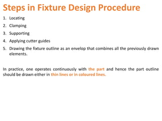
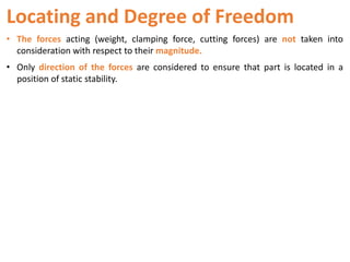
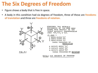
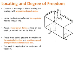
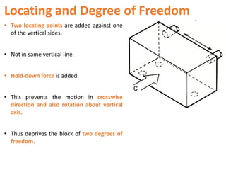
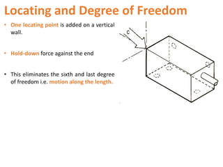
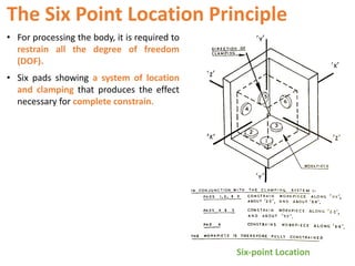
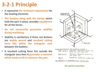
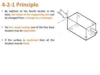


The document summarizes the key steps in the fixture design procedure: 1) locating, 2) clamping, 3) supporting, 4) applying cutter guides, and 5) drawing the fixture outline. It discusses locating and degrees of freedom, describing how locating elements are used to restrict the six degrees of freedom of an object. Specific examples are provided to illustrate how locating points can be applied to a rectangular block to restrict its motion and rotations. The document also discusses clamping elements, support, cutter guidance, and completing the fixture body. Common locating principles like six-point location, 3-2-1 principle, and 4-2-1 principle are explained.


