Download as ODP, PPTX
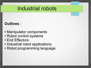


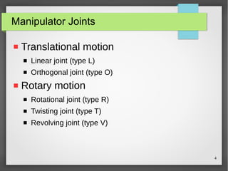


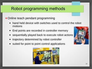


The document outlines the key components of industrial robots including manipulator components, end effectors, control systems, applications, and programming languages. It describes how manipulators consist of joints and links that provide various degrees of freedom and discusses common joint types. The document also examines different robot configurations, control system types from limited sequence to intelligent control, applications in material handling and processing, and programming methods like teach pendant and offline programming.