Downloaded 823 times
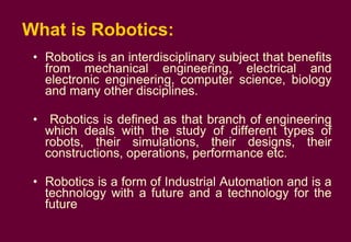
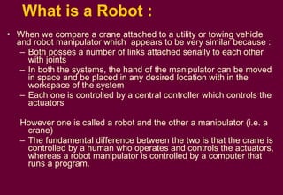
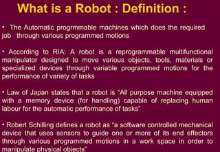
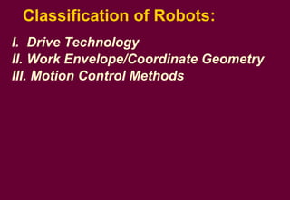
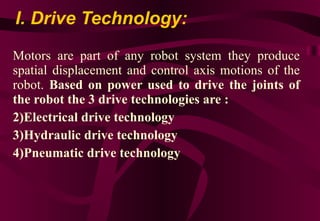
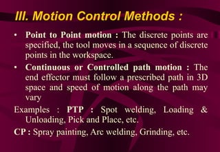
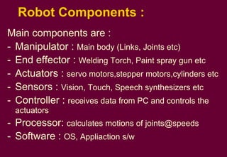
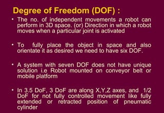
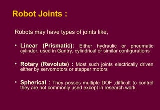
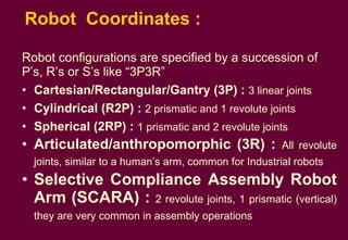
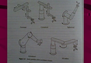

The document provides an introduction to robotics, including definitions of key terms: - A robot is an automatically controlled, reprogrammable device designed to perform tasks normally done by humans. - Robots are classified based on their drive technology, work envelope/coordinate geometry, and motion control methods. - Robotic systems have components like manipulators, end effectors, actuators, sensors, controllers, and software to allow various applications in manufacturing and other industries.