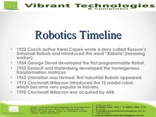
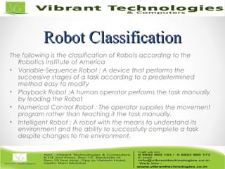
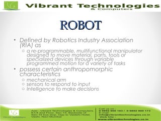
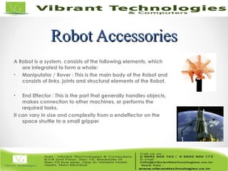
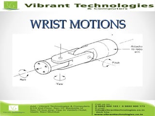
Introduction toIntroduction to
RoboticsRobotics
Robotics TimelineRobotics Timeline
• 1922 Czech author Karel Capek wrote a story called Rossum’s
Universal Robots and introduced the word “Rabota”(meaning
worker)
• 1954 George Devol developed the first programmable Robot.
• 1955 Denavit and Hartenberg developed the homogenous
transformation matrices
• 1962 Unimation was formed, first industrial Robots appeared.
• 1973 Cincinnati Milacron introduced the T3 model robot,
which became very popular in industry.
• 1990 Cincinnati Milacron was acquired by ABB
Robot ClassificationRobot Classification
The following is the classification of Robots according to the
Robotics Institute of America
• Variable-Sequence Robot : A device that performs the
successive stages of a task according to a predetermined
method easy to modify
• Playback Robot :A human operator performs the task manually
by leading the Robot
• Numerical Control Robot : The operator supplies the movement
program rather than teaching it the task manually.
• Intelligent Robot : A robot with the means to understand its
environment and the ability to successfully complete a task
despite changes to the environment.
ROBOTROBOT
• Defined by Robotics Industry Association
(RIA) as
o a re-programmable, multifunctional manipulator
designed to move material, parts, tools or
specialized devices through variable
programmed motion for a variety of tasks
• possess certain anthropomorphic
characteristics
o mechanical arm
o sensors to respond to input
o Intelligence to make decisions
Robot AccessoriesRobot Accessories
A Robot is a system, consists of the following elements, which
are integrated to form a whole:
• Manipulator / Rover : This is the main body of the Robot and
consists of links, joints and structural elements of the Robot.
• End Effector : This is the part that generally handles objects,
makes connection to other machines, or performs the
required tasks.
It can vary in size and complexity from a endeffector on the
space shuttle to a small gripper
AccessoriesAccessories
• Acutators : Actuators are the muscles of the manipulators.
Common types of actuators are servomotors, stepper motors,
pneumatic cylinders etc.
• Sensors : Sensors are used to collect information about the
internal state of the robot or to communicate with the outside
environment. Robots are often equipped with external sensory
devices such as a vision system, touch and tactile sensors etc
which help to communicate with the environment
• Controller : The controller receives data from the computer,
controls the motions of the actuator and coordinates these
motions with the sensory feedback information.
Robot ConfigurationsRobot Configurations
Some of the commonly used configurations in Robotics are
• Cartesian/Rectangular Gantry(3P) : These Robots are made of
3 Linear joints that orient the end effector, which are usually
followed by additional revolute joints.
Cartesian Robot - WorkCartesian Robot - Work
EnvelopeEnvelope
Robot ConfigurationsRobot Configurations
(cont’d)(cont’d)
• Cylindrical (R2P): Cylindrical coordinate Robots have 2
prismatic joints and one revolute joint.
Cylindrical Robot - WorkCylindrical Robot - Work
EnvelopeEnvelope
Robot ConfigurationsRobot Configurations
(cont’d)(cont’d)
• Spherical joint (2RP): They follow a spherical coordinate
system, which has one
Spherical Robot - WorkSpherical Robot - Work
EnvelopeEnvelope
Robot ConfigurationsRobot Configurations
(cont’d)(cont’d)
• Articulated/anthropomorphic(3R) :An articulated robot’s joints
are all revolute, similar to a human’s arm.
Robot ConfigurationsRobot Configurations
(cont’d)(cont’d)
• Selective Compliance Assembly Robot Arm (SCARA) (2R1P):
They have two revolute joints that are parallel and allow the
Robot to move in a horizontal plane, plus an additional
prismatic joint that moves vertically
Robot ConfigurationsRobot Configurations
Reference FramesReference Frames
• World Reference Frame which is a universal coordinate frame, as defined
by the x-y-z axes. In this case the joints of the robot move simultaneously
so as to create motions along the three major axes.
• Joint Reference Frame which is used to specify movements of each
individual joint of the Robot. In this case each joint may be accessed
individually and thus only one joint moves at a time.
• Tool Reference Frame which specifies the movements of the Robots
hand relative to the frame attached to the hand. The x’,y’and z’ axes
attached to the hand define the motions of the hand relative to this
local frame. All joints of the Robot move simultaneously to create
coordinated motions about the Tool frame.
Robot Reference FramesRobot Reference Frames
Work Envelope conceptWork Envelope concept
• Depending on the configuration and size of
the links and wrist joints, robots can reach a
collection of points called a Workspace.
• Alternately Workspace may be found
empirically, by moving each joint through its
range of motions and combining all space it
can reach and subtracting what space it
cannot reach
Pure Spherical Jointed Arm - Work envelope
2) Parallelogram Jointed
WRISTWRIST
• typically has 3 degrees of freedom
o Roll involves rotating the wrist about the arm axis
o Pitch up-down rotation of the wrist
o Yaw left-right rotation of the wrist
• End effector is mounted on the wrist
WRIST MOTIONSWRIST MOTIONS
CONTROL METHODSCONTROL METHODS
• Non Servo Control
o implemented by setting limits or mechanical stops for each joint
and sequencing the actuation of each joint to accomplish the
cycle
o end point robot, limited sequence robot, bang-bang robot
o No control over the motion at the intermediate points, only end
points are known
24
• Programming accomplished by
o setting desired sequence of moves
o adjusting end stops for each axis accordingly
o the sequence of moves is controlled by a “squencer”,
which uses feedback received from the end stops to
index to next step in the program
• Low cost and easy to maintain, reliable
• relatively high speed
• repeatability of up to 0.01 inch
• limited flexibility
• typically hydraulic, pneumatic drives
• Servo Control
o Point to point Control
o Continuous Path Control
• Closed Loop control used to monitor position,
velocity (other variables) of each joint
Point-to-Point ControlPoint-to-Point Control
• Only the end points are programmed, the path
used to connect the end points are computed by
the controller
• user can control velocity, and may permit linear or
piece wise linear motion
• Feedback control is used during motion to ascertain
that individual joints have achieved desired
location
• Often used hydraulic drives, recent trend towards
servomotors
• loads up to 500lb and large reach
• Applications
o pick and place type operations
o palletizing
o machine loading
Continuous PathContinuous Path
ControlledControlled
• in addition to the control over the endpoints, the
path taken by the end effector can be controlled
• Path is controlled by manipulating the joints
throughout the entire motion, via closed loop
control
• Applications:
o spray painting, polishing, grinding, arc welding
ROBOTROBOT
PROGRAMMINGPROGRAMMING
• Typically performed using one of the following
o On line
• teach pendant
• lead through programming
o Off line
• robot programming languages
• task level programming
Use of Teach PendantUse of Teach Pendant
• hand held device with switches used to control the
robot motions
• End points are recorded in controller memory
• sequentially played back to execute robot actions
• trajectory determined by robot controller
• suited for point to point control applications
• Easy to use, no special programming skills required
• Useful when programming robots for wide range of
repetitive tasks for long production runs
• RAPID
Lead ThroughLead Through
ProgrammingProgramming
• lead the robot physically through the required
sequence of motions
• trajectory and endpoints are recorded, using a
sampling routine which records points at 60-80 times
a second
• when played back results in a smooth continuous
motion
• large memory requirements
Programming LanguagesProgramming Languages
• Motivation
o need to interface robot control system to external sensors, to
provide “real time” changes based on sensory equipment
o computing based on geometry of environment
o ability to interface with CAD/CAM systems
o meaningful task descriptions
o off-line programming capability
• Large number of robot languages available
o AML, VAL, AL, RAIL, RobotStudio, etc. (200+)
• Each robot manufacturer has their own robot
programming language
• No standards exist
• Portability of programs virtually non-existent
In-class ExerciseIn-class Exercise
• As a group, discuss an activity that you think could
be automated by using a robot.
• Define the tasks that the robot will perform.
• What kind of special tooling is required? Sketch if
you will use any.
• Can the activity be justified economically? Show
your development – do not simply say yes or no.
ThankThank You !!!You !!!
For More Information click below link:
Follow Us on:
http://vibranttechnologies.co.in/robotics-classes-in-mumbai.html

ROBOTICS - Introduction to Robotics

  • 2.
  • 3.
    Robotics TimelineRobotics Timeline •1922 Czech author Karel Capek wrote a story called Rossum’s Universal Robots and introduced the word “Rabota”(meaning worker) • 1954 George Devol developed the first programmable Robot. • 1955 Denavit and Hartenberg developed the homogenous transformation matrices • 1962 Unimation was formed, first industrial Robots appeared. • 1973 Cincinnati Milacron introduced the T3 model robot, which became very popular in industry. • 1990 Cincinnati Milacron was acquired by ABB
  • 4.
    Robot ClassificationRobot Classification Thefollowing is the classification of Robots according to the Robotics Institute of America • Variable-Sequence Robot : A device that performs the successive stages of a task according to a predetermined method easy to modify • Playback Robot :A human operator performs the task manually by leading the Robot • Numerical Control Robot : The operator supplies the movement program rather than teaching it the task manually. • Intelligent Robot : A robot with the means to understand its environment and the ability to successfully complete a task despite changes to the environment.
  • 5.
    ROBOTROBOT • Defined byRobotics Industry Association (RIA) as o a re-programmable, multifunctional manipulator designed to move material, parts, tools or specialized devices through variable programmed motion for a variety of tasks • possess certain anthropomorphic characteristics o mechanical arm o sensors to respond to input o Intelligence to make decisions
  • 6.
    Robot AccessoriesRobot Accessories ARobot is a system, consists of the following elements, which are integrated to form a whole: • Manipulator / Rover : This is the main body of the Robot and consists of links, joints and structural elements of the Robot. • End Effector : This is the part that generally handles objects, makes connection to other machines, or performs the required tasks. It can vary in size and complexity from a endeffector on the space shuttle to a small gripper
  • 7.
    AccessoriesAccessories • Acutators :Actuators are the muscles of the manipulators. Common types of actuators are servomotors, stepper motors, pneumatic cylinders etc. • Sensors : Sensors are used to collect information about the internal state of the robot or to communicate with the outside environment. Robots are often equipped with external sensory devices such as a vision system, touch and tactile sensors etc which help to communicate with the environment • Controller : The controller receives data from the computer, controls the motions of the actuator and coordinates these motions with the sensory feedback information.
  • 8.
    Robot ConfigurationsRobot Configurations Someof the commonly used configurations in Robotics are • Cartesian/Rectangular Gantry(3P) : These Robots are made of 3 Linear joints that orient the end effector, which are usually followed by additional revolute joints.
  • 9.
    Cartesian Robot -WorkCartesian Robot - Work EnvelopeEnvelope
  • 10.
    Robot ConfigurationsRobot Configurations (cont’d)(cont’d) •Cylindrical (R2P): Cylindrical coordinate Robots have 2 prismatic joints and one revolute joint.
  • 11.
    Cylindrical Robot -WorkCylindrical Robot - Work EnvelopeEnvelope
  • 12.
    Robot ConfigurationsRobot Configurations (cont’d)(cont’d) •Spherical joint (2RP): They follow a spherical coordinate system, which has one
  • 13.
    Spherical Robot -WorkSpherical Robot - Work EnvelopeEnvelope
  • 14.
    Robot ConfigurationsRobot Configurations (cont’d)(cont’d) •Articulated/anthropomorphic(3R) :An articulated robot’s joints are all revolute, similar to a human’s arm.
  • 15.
    Robot ConfigurationsRobot Configurations (cont’d)(cont’d) •Selective Compliance Assembly Robot Arm (SCARA) (2R1P): They have two revolute joints that are parallel and allow the Robot to move in a horizontal plane, plus an additional prismatic joint that moves vertically
  • 16.
  • 17.
    Reference FramesReference Frames •World Reference Frame which is a universal coordinate frame, as defined by the x-y-z axes. In this case the joints of the robot move simultaneously so as to create motions along the three major axes. • Joint Reference Frame which is used to specify movements of each individual joint of the Robot. In this case each joint may be accessed individually and thus only one joint moves at a time. • Tool Reference Frame which specifies the movements of the Robots hand relative to the frame attached to the hand. The x’,y’and z’ axes attached to the hand define the motions of the hand relative to this local frame. All joints of the Robot move simultaneously to create coordinated motions about the Tool frame.
  • 18.
  • 19.
    Work Envelope conceptWorkEnvelope concept • Depending on the configuration and size of the links and wrist joints, robots can reach a collection of points called a Workspace. • Alternately Workspace may be found empirically, by moving each joint through its range of motions and combining all space it can reach and subtracting what space it cannot reach
  • 20.
    Pure Spherical JointedArm - Work envelope
  • 21.
  • 22.
    WRISTWRIST • typically has3 degrees of freedom o Roll involves rotating the wrist about the arm axis o Pitch up-down rotation of the wrist o Yaw left-right rotation of the wrist • End effector is mounted on the wrist
  • 23.
  • 24.
    CONTROL METHODSCONTROL METHODS •Non Servo Control o implemented by setting limits or mechanical stops for each joint and sequencing the actuation of each joint to accomplish the cycle o end point robot, limited sequence robot, bang-bang robot o No control over the motion at the intermediate points, only end points are known 24
  • 25.
    • Programming accomplishedby o setting desired sequence of moves o adjusting end stops for each axis accordingly o the sequence of moves is controlled by a “squencer”, which uses feedback received from the end stops to index to next step in the program • Low cost and easy to maintain, reliable • relatively high speed • repeatability of up to 0.01 inch • limited flexibility • typically hydraulic, pneumatic drives
  • 26.
    • Servo Control oPoint to point Control o Continuous Path Control • Closed Loop control used to monitor position, velocity (other variables) of each joint
  • 27.
    Point-to-Point ControlPoint-to-Point Control •Only the end points are programmed, the path used to connect the end points are computed by the controller • user can control velocity, and may permit linear or piece wise linear motion • Feedback control is used during motion to ascertain that individual joints have achieved desired location
  • 28.
    • Often usedhydraulic drives, recent trend towards servomotors • loads up to 500lb and large reach • Applications o pick and place type operations o palletizing o machine loading
  • 29.
    Continuous PathContinuous Path ControlledControlled •in addition to the control over the endpoints, the path taken by the end effector can be controlled • Path is controlled by manipulating the joints throughout the entire motion, via closed loop control • Applications: o spray painting, polishing, grinding, arc welding
  • 30.
    ROBOTROBOT PROGRAMMINGPROGRAMMING • Typically performedusing one of the following o On line • teach pendant • lead through programming o Off line • robot programming languages • task level programming
  • 31.
    Use of TeachPendantUse of Teach Pendant • hand held device with switches used to control the robot motions • End points are recorded in controller memory • sequentially played back to execute robot actions • trajectory determined by robot controller • suited for point to point control applications
  • 32.
    • Easy touse, no special programming skills required • Useful when programming robots for wide range of repetitive tasks for long production runs • RAPID
  • 33.
    Lead ThroughLead Through ProgrammingProgramming •lead the robot physically through the required sequence of motions • trajectory and endpoints are recorded, using a sampling routine which records points at 60-80 times a second • when played back results in a smooth continuous motion • large memory requirements
  • 34.
    Programming LanguagesProgramming Languages •Motivation o need to interface robot control system to external sensors, to provide “real time” changes based on sensory equipment o computing based on geometry of environment o ability to interface with CAD/CAM systems o meaningful task descriptions o off-line programming capability
  • 35.
    • Large numberof robot languages available o AML, VAL, AL, RAIL, RobotStudio, etc. (200+) • Each robot manufacturer has their own robot programming language • No standards exist • Portability of programs virtually non-existent
  • 36.
    In-class ExerciseIn-class Exercise •As a group, discuss an activity that you think could be automated by using a robot. • Define the tasks that the robot will perform. • What kind of special tooling is required? Sketch if you will use any. • Can the activity be justified economically? Show your development – do not simply say yes or no.
  • 37.
    ThankThank You !!!You!!! For More Information click below link: Follow Us on: http://vibranttechnologies.co.in/robotics-classes-in-mumbai.html