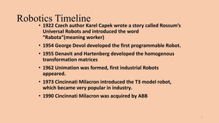
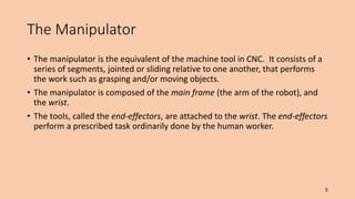
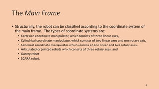
Industrial Robots
By
Asstt. Prof. Abhay S. Gore
Dept. of Mechanical Engg.
MIT (T), Aurangabad
Robotics Timeline
• 1922 Czech author Karel Capek wrote a story called Rossum’s
Universal Robots and introduced the word
“Rabota”(meaning worker)
• 1954 George Devol developed the first programmable Robot.
• 1955 Denavit and Hartenberg developed the homogenous
transformation matrices
• 1962 Unimation was formed, first industrial Robots
appeared.
• 1973 Cincinnati Milacron introduced the T3 model robot,
which became very popular in industry.
• 1990 Cincinnati Milacron was acquired by ABB
2
The Three Laws of Robotics
• A robot may not injure a human being, or, through inaction, allow a
human being to come to harm.
• A robot must obey the orders given it by human beings except where
such orders would conflict with the First Law.
• A robot must protect its own existence as long as such protection
does not conflict with the First or Second Law.
3
• A programmable device equipped with a tool that can move along several
directions.
4
Stand-Alone
Operation: once a
program is entered,
the robot can function
with or without further
human intervention.
The Manipulator
• The manipulator is the equivalent of the machine tool in CNC. It consists of a
series of segments, jointed or sliding relative to one another, that performs
the work such as grasping and/or moving objects.
• The manipulator is composed of the main frame (the arm of the robot), and
the wrist.
• The tools, called the end-effectors, are attached to the wrist. The end-effectors
perform a prescribed task ordinarily done by the human worker.
5
The Main Frame
• Structurally, the robot can be classified according to the coordinate system of
the main frame. The types of coordinate systems are:
• Cartesian coordinate manipulator, which consists of three linear axes,
• Cylindrical coordinate manipulator, which consists of two linear axes and one rotary axis,
• Spherical coordinate manipulator which consists of one linear and two rotary axes,
• Articulated or jointed robots which consists of three rotary axes, and
• Gantry robot
• SCARA robot.
6
Cartesian Robot
7
Cylindrical Robot
8
Spherical Robot
9
Articulated (Jointed) Robot
10
Gantry Robot
11
SCARA Robot (Selective Compliant Articulated
Robot Assembly)
12
Work Envelope concept
• Depending on the configuration and size of the links and wrist joints,
robots can reach a collection of points called a Workspace.
• Alternately Workspace may be found empirically, by moving each
joint through its range of motions and combining all space it can
reach and subtracting what space it cannot reach
13
Pure Spherical Jointed Arm - Work envelope
14
2) Parallelogram Jointed
15
The Wrist
• The end-effectors is connected to the main frame of the robot through the
wrist.
• The wrist has three rotary axes -- roll, bend (pitch), and swivel (yaw).
• The end-effectors. Attached to the wrist is the end-effectors. The end-
effectors is the robot's “hand.” The most common end-effectors is the
gripper, which is a device by which a robot may grasp and hold external
objects.
• Other standard end-effectors include welding torch, magnetic vacuum, gun
mounts for spray painting or coating operations, hydraulic toggle, and custom
made tools.
16
Key Terms
• Repeatability - Variability in returning to the same previously taught
position/configuration
• Accuracy - Variability in moving to a target in space that has not been
previously taught
• Tool speed - Linear speed capability when tool moving along a curvilinear
path
• Screw speed - Rotational speed when tool is being rotated about an axis in
space
• Joint interpolated motion - Motion where joint taking longest time to
make the joint change governs the motion and the other joints are slowed in
proportion so that all joint accomplish their joint changes simultaneously
with the slowest joint
Key Terms (cont...)
• TCF - Tool or terminal control frame
• TCP - Tool /terminal control point
• Joint limits - Either the software or physical hardware limits which constrain
the operating range of a joint on a robot. The software limits have a smaller range
than the hardware limits.
• Joint speed limits - Speed limit for robot joints, which limit how fast the links
of a robot may translate or rotate.
• Point-to-point motion- Characterized by starting and stopping between
configurations or as the tool is moved between targets.
18
Key Terms (cont..)
• Continuous path motion- Characterized by blending of motion between
configurations or targets, usually with the loss of path accuracy at the target
transitions, as the robot moves between configurations/targets.
• Interpolation (kinematic) capabilities - Robot usually capable of both
forward and inverse kinematics. Both combine to give the robot the capability to
move in joint space and in Cartesian space. We typically refer to the
moves as joint, linear, or circular interpolation.
• Forward kinematics - Specifying the joint values to accomplish a robot
move to a new configuration in space. These may not be simple as it seems
because secondary joints such as four-bar linkages, ball screws, etc. may be
required to accomplish this motion.
19
Key Terms (cont..)
• Inverse kinematics - Solving a mathematical model of the robot kinematics
to determine the necessary joint values to move the tool to a desired target
(frame) in space. This is accomplished by frame representation whereby a triad
(xyz axes) is attached to the tool on the robot and a target frame is attached to the
part or operating point in the workcell. The inverse kinematics determine the
joint values required to align the tool triad with the target triad.
• I/O - Input/output which consist of ON/OFF signal values, threshold values, or
analog signal values which allow the control of or response to external
devices/sensors as required to sequence workcell operations.
• Programming language - The language and logical constructs used to
program the set of operational instructions used to control robot movement and
interact with sensors and other cell devices.
• Multi-tasking - Ability to process more than one program at a time or process
I/O concurrently.
20
Key Terms (cont..)
• Load capability - Force and torque capability of the robot at its tool interface
• Teach Pendant - Operator interface device used to teach/save robot
configurations and program simple instructions.
21
Resolution,Accuracy,Repeatability
• Resolution is the smallest increment of distance that can be read and acted
upon by an automatic control system of a robot.
• The unit of measure is the basic resolution unit (BRU).
• The accuracy of an industrial robot is the ability of the robot to make a motion
with an end point as specified by a program.
• The closeness of agreement of repeated position movement under the same
conditions to the same location is called the repeatability of the robot.
22
Programming
• An industrial robot can be programmed using the
• Manual teaching method,
• Lead-through method, or a
• Programming language.
23
Applications
• Perhaps the most extensive applications of industrial robots are in
jobs involving repetitive tasks. Industrial robots installed to-date are
in
• Material handling (about 40%),
• Painting and arc welding (45%),
• Inspection, assembly and
• Other operations (15%).
24
• Operations that require precise positioning control.
• For example, in spray painting where severe articulation is required.
• Use of industrial robots in sand blasting is on the rise not only because of the
abrasive environment, but the severe articulation requirements of the
process.
25
• In areas where hazardous working conditions exist and/or where
heavy parts are involved.
• For example, in unloading of die casting machines, the workplace is dirty and
hot (molten metal); in spot welding operations, the welding guns are heavy
and the work cycles rigorous; and in investment casting, the environment is
abrasive and of the loads heavy.
• Industrial robots are also replacing the human operator in corrosive
environment, such as handling of dangerous chemicals.
26
• Hazards, operator tasks, inspection, quality, part presentation, part weight,
product variation, product runs, frequency of changeover, process variables,
process equipment, floor space, and cycle time, are some of the variable that
must be examined in justifying the use of industrial robots.
• However, industrial robots should not be treated simply as an emulation of
human work. More importantly, the justification process should reflect an
accurate implementation of corporate manufacturing plans for competitive
advantage and productivity improvement.
27
The Course at a Glimpse: Kinematics
F(robot variables) = world coordinates
x = x(1,, n)
y = y(1,, n)
z = z(1,, n)
• In a “cascade” robot, Kinematics is a single-valued
mapping.
• “Easy” to compute.
28
Kinematics: Example
1= , 2=r
1 r  4.5
0   50o

x = r cos 
y = r sin 
workspace
29
Inverse Kinematics
• G(world coordinates) = robot variables
1 = 1(x,y,z)

N = N(x,y,z)
• The inverse problem has a lot of geometrical difficulties
• inversion may not be unique!
30
Inverse Kinematics: Example
2
1
Make unique by constraining angles
31
Trajectory Planning
• Get from (xo, yo, zo) to (xf, yf, zf)
• In robot coordinates: o  f
• Planning in robot coordinates is easier, but we loose
visualization.
• Additional constraints may be desirable:
• smoothness
• dynamic limitations
• obstacles
32
Programming Languages
• Motivation
• need to interface robot control system to external sensors, to provide “real
time” changes based on sensory equipment
• computing based on geometry of environment
• ability to interface with CAD/CAM systems
• meaningful task descriptions
• off-line programming capability
33
• Large number of robot languages available
• AML, VAL, AL, RAIL, RobotStudio, etc. (200+)
• Each robot manufacturer has their own robot programming language
• No standards exist
• Portability of programs virtually non-existent
34
Advantages
• Greater flexibility, re-programmability, kinematics dexterity
• Greater response time to inputs than humans
• Improved product quality
• Maximize capital intensive equipment in multiple work shifts
• Accident reduction
• Reduction of hazardous exposure for human workers
• Automation less susceptible to work stoppages
35
Disadvantages
• Replacement of human labor
• Greater unemployment
• Significant retraining costs for both unemployed and
users of new technology
• Advertised technology does not always disclose some of
the hidden disadvantages
• Hidden costs because of the associated technology that
must be purchased and integrated into a functioning
cell. Typically, a functioning cell will cost 3-10 times
the cost of the robot.
36
Limitations
• Assembly dexterity does not match that of human beings,
particularly where eye-hand coordination required.
• Payload to robot weight ratio is poor, often less than 5%.
• Robot structural configuration may limit joint movement.
• Work volumes can be constrained by parts or tooling/sensors
added to the robot.
• Robot repeatability/accuracy can constrain the range of
potential applications.
• Closed architectures of modern robot control systems make it
difficult to automate cells.
37

Industrial_Robots_pptx.pptx

  • 1.
    Industrial Robots By Asstt. Prof.Abhay S. Gore Dept. of Mechanical Engg. MIT (T), Aurangabad
  • 2.
    Robotics Timeline • 1922Czech author Karel Capek wrote a story called Rossum’s Universal Robots and introduced the word “Rabota”(meaning worker) • 1954 George Devol developed the first programmable Robot. • 1955 Denavit and Hartenberg developed the homogenous transformation matrices • 1962 Unimation was formed, first industrial Robots appeared. • 1973 Cincinnati Milacron introduced the T3 model robot, which became very popular in industry. • 1990 Cincinnati Milacron was acquired by ABB 2
  • 3.
    The Three Lawsof Robotics • A robot may not injure a human being, or, through inaction, allow a human being to come to harm. • A robot must obey the orders given it by human beings except where such orders would conflict with the First Law. • A robot must protect its own existence as long as such protection does not conflict with the First or Second Law. 3
  • 4.
    • A programmabledevice equipped with a tool that can move along several directions. 4 Stand-Alone Operation: once a program is entered, the robot can function with or without further human intervention.
  • 5.
    The Manipulator • Themanipulator is the equivalent of the machine tool in CNC. It consists of a series of segments, jointed or sliding relative to one another, that performs the work such as grasping and/or moving objects. • The manipulator is composed of the main frame (the arm of the robot), and the wrist. • The tools, called the end-effectors, are attached to the wrist. The end-effectors perform a prescribed task ordinarily done by the human worker. 5
  • 6.
    The Main Frame •Structurally, the robot can be classified according to the coordinate system of the main frame. The types of coordinate systems are: • Cartesian coordinate manipulator, which consists of three linear axes, • Cylindrical coordinate manipulator, which consists of two linear axes and one rotary axis, • Spherical coordinate manipulator which consists of one linear and two rotary axes, • Articulated or jointed robots which consists of three rotary axes, and • Gantry robot • SCARA robot. 6
  • 7.
  • 8.
  • 9.
  • 10.
  • 11.
  • 12.
    SCARA Robot (SelectiveCompliant Articulated Robot Assembly) 12
  • 13.
    Work Envelope concept •Depending on the configuration and size of the links and wrist joints, robots can reach a collection of points called a Workspace. • Alternately Workspace may be found empirically, by moving each joint through its range of motions and combining all space it can reach and subtracting what space it cannot reach 13
  • 14.
    Pure Spherical JointedArm - Work envelope 14
  • 15.
  • 16.
    The Wrist • Theend-effectors is connected to the main frame of the robot through the wrist. • The wrist has three rotary axes -- roll, bend (pitch), and swivel (yaw). • The end-effectors. Attached to the wrist is the end-effectors. The end- effectors is the robot's “hand.” The most common end-effectors is the gripper, which is a device by which a robot may grasp and hold external objects. • Other standard end-effectors include welding torch, magnetic vacuum, gun mounts for spray painting or coating operations, hydraulic toggle, and custom made tools. 16
  • 17.
    Key Terms • Repeatability- Variability in returning to the same previously taught position/configuration • Accuracy - Variability in moving to a target in space that has not been previously taught • Tool speed - Linear speed capability when tool moving along a curvilinear path • Screw speed - Rotational speed when tool is being rotated about an axis in space • Joint interpolated motion - Motion where joint taking longest time to make the joint change governs the motion and the other joints are slowed in proportion so that all joint accomplish their joint changes simultaneously with the slowest joint
  • 18.
    Key Terms (cont...) •TCF - Tool or terminal control frame • TCP - Tool /terminal control point • Joint limits - Either the software or physical hardware limits which constrain the operating range of a joint on a robot. The software limits have a smaller range than the hardware limits. • Joint speed limits - Speed limit for robot joints, which limit how fast the links of a robot may translate or rotate. • Point-to-point motion- Characterized by starting and stopping between configurations or as the tool is moved between targets. 18
  • 19.
    Key Terms (cont..) •Continuous path motion- Characterized by blending of motion between configurations or targets, usually with the loss of path accuracy at the target transitions, as the robot moves between configurations/targets. • Interpolation (kinematic) capabilities - Robot usually capable of both forward and inverse kinematics. Both combine to give the robot the capability to move in joint space and in Cartesian space. We typically refer to the moves as joint, linear, or circular interpolation. • Forward kinematics - Specifying the joint values to accomplish a robot move to a new configuration in space. These may not be simple as it seems because secondary joints such as four-bar linkages, ball screws, etc. may be required to accomplish this motion. 19
  • 20.
    Key Terms (cont..) •Inverse kinematics - Solving a mathematical model of the robot kinematics to determine the necessary joint values to move the tool to a desired target (frame) in space. This is accomplished by frame representation whereby a triad (xyz axes) is attached to the tool on the robot and a target frame is attached to the part or operating point in the workcell. The inverse kinematics determine the joint values required to align the tool triad with the target triad. • I/O - Input/output which consist of ON/OFF signal values, threshold values, or analog signal values which allow the control of or response to external devices/sensors as required to sequence workcell operations. • Programming language - The language and logical constructs used to program the set of operational instructions used to control robot movement and interact with sensors and other cell devices. • Multi-tasking - Ability to process more than one program at a time or process I/O concurrently. 20
  • 21.
    Key Terms (cont..) •Load capability - Force and torque capability of the robot at its tool interface • Teach Pendant - Operator interface device used to teach/save robot configurations and program simple instructions. 21
  • 22.
    Resolution,Accuracy,Repeatability • Resolution isthe smallest increment of distance that can be read and acted upon by an automatic control system of a robot. • The unit of measure is the basic resolution unit (BRU). • The accuracy of an industrial robot is the ability of the robot to make a motion with an end point as specified by a program. • The closeness of agreement of repeated position movement under the same conditions to the same location is called the repeatability of the robot. 22
  • 23.
    Programming • An industrialrobot can be programmed using the • Manual teaching method, • Lead-through method, or a • Programming language. 23
  • 24.
    Applications • Perhaps themost extensive applications of industrial robots are in jobs involving repetitive tasks. Industrial robots installed to-date are in • Material handling (about 40%), • Painting and arc welding (45%), • Inspection, assembly and • Other operations (15%). 24
  • 25.
    • Operations thatrequire precise positioning control. • For example, in spray painting where severe articulation is required. • Use of industrial robots in sand blasting is on the rise not only because of the abrasive environment, but the severe articulation requirements of the process. 25
  • 26.
    • In areaswhere hazardous working conditions exist and/or where heavy parts are involved. • For example, in unloading of die casting machines, the workplace is dirty and hot (molten metal); in spot welding operations, the welding guns are heavy and the work cycles rigorous; and in investment casting, the environment is abrasive and of the loads heavy. • Industrial robots are also replacing the human operator in corrosive environment, such as handling of dangerous chemicals. 26
  • 27.
    • Hazards, operatortasks, inspection, quality, part presentation, part weight, product variation, product runs, frequency of changeover, process variables, process equipment, floor space, and cycle time, are some of the variable that must be examined in justifying the use of industrial robots. • However, industrial robots should not be treated simply as an emulation of human work. More importantly, the justification process should reflect an accurate implementation of corporate manufacturing plans for competitive advantage and productivity improvement. 27
  • 28.
    The Course ata Glimpse: Kinematics F(robot variables) = world coordinates x = x(1,, n) y = y(1,, n) z = z(1,, n) • In a “cascade” robot, Kinematics is a single-valued mapping. • “Easy” to compute. 28
  • 29.
    Kinematics: Example 1= ,2=r 1 r  4.5 0   50o  x = r cos  y = r sin  workspace 29
  • 30.
    Inverse Kinematics • G(worldcoordinates) = robot variables 1 = 1(x,y,z)  N = N(x,y,z) • The inverse problem has a lot of geometrical difficulties • inversion may not be unique! 30
  • 31.
    Inverse Kinematics: Example 2 1 Makeunique by constraining angles 31
  • 32.
    Trajectory Planning • Getfrom (xo, yo, zo) to (xf, yf, zf) • In robot coordinates: o  f • Planning in robot coordinates is easier, but we loose visualization. • Additional constraints may be desirable: • smoothness • dynamic limitations • obstacles 32
  • 33.
    Programming Languages • Motivation •need to interface robot control system to external sensors, to provide “real time” changes based on sensory equipment • computing based on geometry of environment • ability to interface with CAD/CAM systems • meaningful task descriptions • off-line programming capability 33
  • 34.
    • Large numberof robot languages available • AML, VAL, AL, RAIL, RobotStudio, etc. (200+) • Each robot manufacturer has their own robot programming language • No standards exist • Portability of programs virtually non-existent 34
  • 35.
    Advantages • Greater flexibility,re-programmability, kinematics dexterity • Greater response time to inputs than humans • Improved product quality • Maximize capital intensive equipment in multiple work shifts • Accident reduction • Reduction of hazardous exposure for human workers • Automation less susceptible to work stoppages 35
  • 36.
    Disadvantages • Replacement ofhuman labor • Greater unemployment • Significant retraining costs for both unemployed and users of new technology • Advertised technology does not always disclose some of the hidden disadvantages • Hidden costs because of the associated technology that must be purchased and integrated into a functioning cell. Typically, a functioning cell will cost 3-10 times the cost of the robot. 36
  • 37.
    Limitations • Assembly dexteritydoes not match that of human beings, particularly where eye-hand coordination required. • Payload to robot weight ratio is poor, often less than 5%. • Robot structural configuration may limit joint movement. • Work volumes can be constrained by parts or tooling/sensors added to the robot. • Robot repeatability/accuracy can constrain the range of potential applications. • Closed architectures of modern robot control systems make it difficult to automate cells. 37