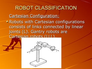
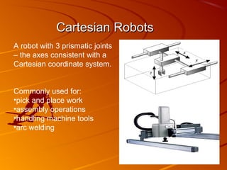
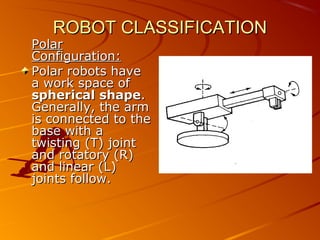
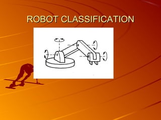
ROBOTICS
           Industrial Robots Definition
         A robot is a programmable arm simulator

“A robot is a re-programmable, multifunction manipulator
designed to move material, parts, tools, or special devices
through variable programmed motions for the performance of
a variety of tasks”
                                  Robot Institute of America
Main Components of Industrial Robots

– Arm or Manipulator
– End effectors
– Drive Mechanism
– Controller
– Custom features: e.g. sensors and transducers
Robotics Terminology
Link: A rigid piece of material connecting joints in a robot.

Joint: The device which allows relative motion between two adjoining
   links in a robot.


A robot joint is a mechanism that
permits relative movement between
parts of a robot arm. The joints of a
robot are designed to enable the
robot to move its end-effectors along
a path from one position to another
as desired.
The Robotic Movements
The basic movements required for a
desired motion of most industrial robots
are:

Rotational movement: This enables the
robot to place its arm in any direction on a
horizontal plane.


Radial movement: This enables the robot to
move its end-effectors radially to reach distant
points.

Vertical movement: This enables the robot
The Robotic Joints
Types of JOINTS
                                                               A robot joint
1) Linear Joint (L)     2) Rotational Joint (R)
  3) Twisting Joint (T)      4) Revolving Joint (V)

 1) Linear Joints are also known as sliding as well as Prismatic joints (L)

    They are called prismatic because the cross section of the joint is
    considered as a generalized prism. They permit links to move in a linear
    relationship.

 Revolute joints permit only angular motion between links. Their variations
   include:
        Rotational joint (R)
        Twisting joint (T)
        Revolving joint (V)
A rotational joint (R)

is identified by its motion, rotation about
antwisting joint (T) the adjoining
A axis perpendicular to
links.
is also a rotational joint, where the
rotation takes place about an axis
that is parallel to both adjoining
links.
A revolving joint (V)
is another rotational joint, where the rotation
takes place perpendicular to one another at
this kind of joint. The rotation involves
revolution of one link about another.
Wrist Movement
The Wrist movement is designed to enable the robot to orient the end
   effector properly with respect to the task to be performed.
Eg. Human hand
To solve the orientation problem, the wrist is normally provided with upto 3
   DOF.
1) Wrist Roll- which involves rotation of the wrist mechanism about the
   arm axis. Also called as wrist swivel.
2) Wrist Pitch- If the wrist roll is in its center position , the pitch would
   involve the up and down rotation of the wrist. Also called as wrist bend.
3) Wrist Yaw- If the wrist roll is in its center position of its range, wrist yaw
   would involve the right or left rotation of the wrist.
Robotics Terminology
DOF degrees-of-freedom: can be defined as the number
of independent motions a device can make. (Also called
mobility)


                 five degrees of freedom
Accuracy
  •The ability of a robot to go to the specified position
  without making a mistake.
  •It is impossible to position a machine exactly.
  •Accuracy is therefore defined as the ability of the robot to
  position itself to the desired location with the minimal
  error (usually 25 µm).

Repeatability
  •The ability of a robot to repeatedly position itself when
  asked to perform a task multiple times.
  •Accuracy is an absolute concept, repeatability is relative.
  •A robot that is repeatable may not be very accurate, visa
  versa.
Joint Notation Scheme
Physical configuration of the robot manipulator can be described by
means of a joint notation scheme .
Considering the arm and body joints first, the letters can be used to
designate the particular robot configuration starting with the joint
closest to the base and proceeding to the joint configuration that
connects to the wrist.

        Robot configuration                  Symbol

        Polar configuration                  TRL

        Cylindrical configuration TLL,LTL,LVL

        Cartesian configuration              LLL

        Joint arm configuration              TRR, VVR
ROBOT CLASSIFICATION
1) Depending on Configuration
2) Depending on type of control system
3) Fixed or variable sequence robot
4) Depending upon generation
5) Servo / nonservo robots
6) Point to Point or continuous controlling robots
ROBOT CLASSIFICATION
Classification Based on Physical
Configuration:
  1. Cartesian configuration
 2.   Cylindrical configuration
 3.   Polar configuration
 4.   Joint-arm configuration
 5.   SCARA
ROBOT CLASSIFICATION
Cartesian Configuration:
Robots with Cartesian configurations
consists of links connected by linear
joints (L). Gantry robots are
Cartesian robots (LLL).
Cartesian Robots
A robot with 3 prismatic joints
– the axes consistent with a
Cartesian coordinate system.


Commonly used for:
•pick and place work
•assembly operations
•handling machine tools
•arc welding
Cartesian Robots
Advantages:
  ability to do straight line insertions into furnaces.
  easy computation and programming.
  most rigid structure for given length.

Disadvantages:
  requires large operating volume.
  exposed guiding surfaces require covering in
  corrosive or dusty environments.
  can only reach front of itself
  axes hard to seal
ROBOT CLASSIFICATION
Cylindrical Configuration:
Robots with cylindrical configuration
have one rotary ( R) joint at the base
and linear (L) joints succeeded to
connect the links.
Cylindrical Robots
A robot with 2 prismatic joints
and a rotary joint – the axes
consistent with a cylindrical
coordinate system.


Commonly used for:
•handling at die-casting
machines
•assembly operations
•handling machine tools
•spot welding
Cylindrical Robots
Advantages:
  can reach all around itself
  rotational axis easy to seal
  relatively easy programming
  rigid enough to handle heavy loads through large working
  space
  good access into cavities and machine openings

Disadvantages:
   can't reach above itself
   linear axes is hard to seal
   won’t reach around obstacles
   exposed drives are difficult to cover from dust and liquids
ROBOT CLASSIFICATION
Polar
Configuration:
Polar robots have
a work space of
spherical shape.
Generally, the arm
is connected to the
base with a
twisting (T) joint
and rotatory (R)
and linear (L)
joints follow.
ROBOT CLASSIFICATION
The designation of the arm for this
configuration can be TRL or TRR.
Robots with the designation TRL are
also called spherical robots. Those
with the designation TRR are also
called articulated robots. An
articulated robot more closely
resembles the human arm.
ROBOT CLASSIFICATION
Joint-arm Configuration:
The jointed-arm is a combination of
cylindrical and articulated
configurations. The arm of the robot
is connected to the base with a
twisting joint. The links in the arm
are connected by rotatory joints.
Many commercially available robots
have this configuration.
ROBOT CLASSIFICATION
Articulated Robots
A robot with at least 3 rotary
joints.


Commonly used for:
•assembly operations
•welding
•weld sealing
•spray painting
•handling at die casting or
fettling machines
Articulated Robots
Advantages:
  all rotary joints allows for maximum flexibility
  any point in total volume can be reached.
  all joints can be sealed from the environment.

Disadvantages:
  extremely difficult to visualize, control, and
  program.
  restricted volume coverage.
  low accuracy
SCARA (Selective Compliance
         Articulated Robot Arm) Robots
A robot with at least 2 parallel
rotary joints.


Commonly used for:
•pick and place work
•assembly operations
SCARA (Selective Compliance
     Articulated Robot Arm) Robots
Advantages:
  high speed.
  height axis is rigid
  large work area for floor space
  moderately easy to program.

Disadvantages:
  limited applications.
  2 ways to reach point
  difficult to program off-line
  highly complex arm
Spherical/Polar Robots
A robot with 1 prismatic joint
and 2 rotary joints – the axes
consistent with a polar
coordinate system.


Commonly used for:
•handling at die casting or
fettling machines
•handling machine tools
•arc/spot welding
Spherical/Polar Robots
Advantages:
  large working envelope.
  two rotary drives are easily sealed against
  liquids/dust.

Disadvantages:
  complex coordinates more difficult to visualize,
  control, and program.
  exposed linear drive.
  low accuracy.
ROBOT CLASSIFICATION
Classification Based on Control
Systems:
– 1. Point-to-point (PTP) control robot
– 2. Continuous-path (CP) control robot
– 3. Controlled-path robot
Point to Point Control Robot
            (PTP):
The PTP robot is capable of moving from
one point to another point.
The locations are recorded in the control
memory. PTP robots do not control the
path to get from one point to the next
point.
Common applications include:
–   component insertion
–   spot welding
–   hole drilling
–   machine loading and unloading
–   assembly operations
Continuous-Path Control Robot (CP):
The CP robot is capable of performing movements
along the controlled path. With CP from one
control, the robot can stop at any specified point
along the controlled path.
All the points along the path must be stored
explicitly in the robot's control memory.
Applications Straight-line motion is the simplest
example for this type of robot. Some continuous-
path controlled robots also have the capability to
follow a smooth curve path that has been defined
by the programmer. In such cases the
programmer manually moves the robot arm
through the desired path and the controller unit
stores a large number of individual point locations
along the path in memory (teach-in).
Continuous-Path Control Robot (CP):

Typical applications include:
– spray painting
– finishing
– gluing
– arc welding operations
Controlled-Path Robot:

In controlled-path robots, the control equipment
can generate paths of different geometry such as
straight lines, circles, and interpolated curves
with a high degree of accuracy. Good accuracy
can be obtained at any point along the specified
path.

Only the start and finish points and the path
definition function must be stored in the robot's
control memory. It is important to mention that
all controlled-path robots have a servo capability
to correct their path.
Robot Specifications

Characteristics        Units
No of Axes             Numbers(eg 1,2)
Max speed/cycle        mm/sec
time
Load carrying          Kg
capacity (pay load)
Reach & stroke         mm
Total orientation      Degrees
Repeatability          --
Precision & Accuracy   mm
Tushar ppt

Tushar ppt

  • 1.
    ROBOTICS Industrial Robots Definition A robot is a programmable arm simulator “A robot is a re-programmable, multifunction manipulator designed to move material, parts, tools, or special devices through variable programmed motions for the performance of a variety of tasks” Robot Institute of America
  • 2.
    Main Components ofIndustrial Robots – Arm or Manipulator – End effectors – Drive Mechanism – Controller – Custom features: e.g. sensors and transducers
  • 3.
    Robotics Terminology Link: Arigid piece of material connecting joints in a robot. Joint: The device which allows relative motion between two adjoining links in a robot. A robot joint is a mechanism that permits relative movement between parts of a robot arm. The joints of a robot are designed to enable the robot to move its end-effectors along a path from one position to another as desired.
  • 4.
    The Robotic Movements Thebasic movements required for a desired motion of most industrial robots are: Rotational movement: This enables the robot to place its arm in any direction on a horizontal plane. Radial movement: This enables the robot to move its end-effectors radially to reach distant points. Vertical movement: This enables the robot
  • 5.
    The Robotic Joints Typesof JOINTS A robot joint 1) Linear Joint (L) 2) Rotational Joint (R) 3) Twisting Joint (T) 4) Revolving Joint (V) 1) Linear Joints are also known as sliding as well as Prismatic joints (L) They are called prismatic because the cross section of the joint is considered as a generalized prism. They permit links to move in a linear relationship. Revolute joints permit only angular motion between links. Their variations include: Rotational joint (R) Twisting joint (T) Revolving joint (V)
  • 6.
    A rotational joint(R) is identified by its motion, rotation about antwisting joint (T) the adjoining A axis perpendicular to links. is also a rotational joint, where the rotation takes place about an axis that is parallel to both adjoining links.
  • 7.
    A revolving joint(V) is another rotational joint, where the rotation takes place perpendicular to one another at this kind of joint. The rotation involves revolution of one link about another.
  • 8.
    Wrist Movement The Wristmovement is designed to enable the robot to orient the end effector properly with respect to the task to be performed. Eg. Human hand To solve the orientation problem, the wrist is normally provided with upto 3 DOF. 1) Wrist Roll- which involves rotation of the wrist mechanism about the arm axis. Also called as wrist swivel. 2) Wrist Pitch- If the wrist roll is in its center position , the pitch would involve the up and down rotation of the wrist. Also called as wrist bend. 3) Wrist Yaw- If the wrist roll is in its center position of its range, wrist yaw would involve the right or left rotation of the wrist.
  • 9.
    Robotics Terminology DOF degrees-of-freedom:can be defined as the number of independent motions a device can make. (Also called mobility) five degrees of freedom
  • 10.
    Accuracy •Theability of a robot to go to the specified position without making a mistake. •It is impossible to position a machine exactly. •Accuracy is therefore defined as the ability of the robot to position itself to the desired location with the minimal error (usually 25 µm). Repeatability •The ability of a robot to repeatedly position itself when asked to perform a task multiple times. •Accuracy is an absolute concept, repeatability is relative. •A robot that is repeatable may not be very accurate, visa versa.
  • 12.
    Joint Notation Scheme Physicalconfiguration of the robot manipulator can be described by means of a joint notation scheme . Considering the arm and body joints first, the letters can be used to designate the particular robot configuration starting with the joint closest to the base and proceeding to the joint configuration that connects to the wrist. Robot configuration Symbol Polar configuration TRL Cylindrical configuration TLL,LTL,LVL Cartesian configuration LLL Joint arm configuration TRR, VVR
  • 13.
    ROBOT CLASSIFICATION 1) Dependingon Configuration 2) Depending on type of control system 3) Fixed or variable sequence robot 4) Depending upon generation 5) Servo / nonservo robots 6) Point to Point or continuous controlling robots
  • 14.
    ROBOT CLASSIFICATION Classification Basedon Physical Configuration: 1. Cartesian configuration 2. Cylindrical configuration 3. Polar configuration 4. Joint-arm configuration 5. SCARA
  • 15.
    ROBOT CLASSIFICATION Cartesian Configuration: Robotswith Cartesian configurations consists of links connected by linear joints (L). Gantry robots are Cartesian robots (LLL).
  • 16.
    Cartesian Robots A robotwith 3 prismatic joints – the axes consistent with a Cartesian coordinate system. Commonly used for: •pick and place work •assembly operations •handling machine tools •arc welding
  • 17.
    Cartesian Robots Advantages: ability to do straight line insertions into furnaces. easy computation and programming. most rigid structure for given length. Disadvantages: requires large operating volume. exposed guiding surfaces require covering in corrosive or dusty environments. can only reach front of itself axes hard to seal
  • 18.
    ROBOT CLASSIFICATION Cylindrical Configuration: Robotswith cylindrical configuration have one rotary ( R) joint at the base and linear (L) joints succeeded to connect the links.
  • 19.
    Cylindrical Robots A robotwith 2 prismatic joints and a rotary joint – the axes consistent with a cylindrical coordinate system. Commonly used for: •handling at die-casting machines •assembly operations •handling machine tools •spot welding
  • 20.
    Cylindrical Robots Advantages: can reach all around itself rotational axis easy to seal relatively easy programming rigid enough to handle heavy loads through large working space good access into cavities and machine openings Disadvantages: can't reach above itself linear axes is hard to seal won’t reach around obstacles exposed drives are difficult to cover from dust and liquids
  • 21.
    ROBOT CLASSIFICATION Polar Configuration: Polar robotshave a work space of spherical shape. Generally, the arm is connected to the base with a twisting (T) joint and rotatory (R) and linear (L) joints follow.
  • 22.
    ROBOT CLASSIFICATION The designationof the arm for this configuration can be TRL or TRR. Robots with the designation TRL are also called spherical robots. Those with the designation TRR are also called articulated robots. An articulated robot more closely resembles the human arm.
  • 23.
    ROBOT CLASSIFICATION Joint-arm Configuration: Thejointed-arm is a combination of cylindrical and articulated configurations. The arm of the robot is connected to the base with a twisting joint. The links in the arm are connected by rotatory joints. Many commercially available robots have this configuration.
  • 24.
  • 25.
    Articulated Robots A robotwith at least 3 rotary joints. Commonly used for: •assembly operations •welding •weld sealing •spray painting •handling at die casting or fettling machines
  • 26.
    Articulated Robots Advantages: all rotary joints allows for maximum flexibility any point in total volume can be reached. all joints can be sealed from the environment. Disadvantages: extremely difficult to visualize, control, and program. restricted volume coverage. low accuracy
  • 27.
    SCARA (Selective Compliance Articulated Robot Arm) Robots A robot with at least 2 parallel rotary joints. Commonly used for: •pick and place work •assembly operations
  • 28.
    SCARA (Selective Compliance Articulated Robot Arm) Robots Advantages: high speed. height axis is rigid large work area for floor space moderately easy to program. Disadvantages: limited applications. 2 ways to reach point difficult to program off-line highly complex arm
  • 29.
    Spherical/Polar Robots A robotwith 1 prismatic joint and 2 rotary joints – the axes consistent with a polar coordinate system. Commonly used for: •handling at die casting or fettling machines •handling machine tools •arc/spot welding
  • 30.
    Spherical/Polar Robots Advantages: large working envelope. two rotary drives are easily sealed against liquids/dust. Disadvantages: complex coordinates more difficult to visualize, control, and program. exposed linear drive. low accuracy.
  • 31.
    ROBOT CLASSIFICATION Classification Basedon Control Systems: – 1. Point-to-point (PTP) control robot – 2. Continuous-path (CP) control robot – 3. Controlled-path robot
  • 32.
    Point to PointControl Robot (PTP): The PTP robot is capable of moving from one point to another point. The locations are recorded in the control memory. PTP robots do not control the path to get from one point to the next point. Common applications include: – component insertion – spot welding – hole drilling – machine loading and unloading – assembly operations
  • 33.
    Continuous-Path Control Robot(CP): The CP robot is capable of performing movements along the controlled path. With CP from one control, the robot can stop at any specified point along the controlled path. All the points along the path must be stored explicitly in the robot's control memory. Applications Straight-line motion is the simplest example for this type of robot. Some continuous- path controlled robots also have the capability to follow a smooth curve path that has been defined by the programmer. In such cases the programmer manually moves the robot arm through the desired path and the controller unit stores a large number of individual point locations along the path in memory (teach-in).
  • 34.
    Continuous-Path Control Robot(CP): Typical applications include: – spray painting – finishing – gluing – arc welding operations
  • 35.
    Controlled-Path Robot: In controlled-pathrobots, the control equipment can generate paths of different geometry such as straight lines, circles, and interpolated curves with a high degree of accuracy. Good accuracy can be obtained at any point along the specified path. Only the start and finish points and the path definition function must be stored in the robot's control memory. It is important to mention that all controlled-path robots have a servo capability to correct their path.
  • 36.
    Robot Specifications Characteristics Units No of Axes Numbers(eg 1,2) Max speed/cycle mm/sec time Load carrying Kg capacity (pay load) Reach & stroke mm Total orientation Degrees Repeatability -- Precision & Accuracy mm