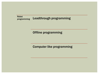
SlideShare a Scribd company logo
by
Dr Vishaldatt
Kohir
Professor
Subject: Computer Integrated Manufacturing
Module 4
ROBOT TECHNOLOGY
Topic : Robot programming , accuracy ,repeatability
and application
Part 3 Robot Application
Part 2 Accuracy, Repeatability
Part 1 Robot programming
Robot
programming Leadthrough programming
Offline programming
Computer like programming
A robot program can be defined as a path in space to be followed by the
manipulator, combined with peripheral actions that support the work cycle.
(1) Lead through programming,
(2) Computer-like robot
(3) Off-line programming.
Lead through programming
The robot is physically moved through the various motions needed to perform a
given task, recording the motions into the robot’s computer memory. This can be
done either by physically (manually) moving the manipulator through the motion
sequence or by using a control box (teach pendent) to drive the manipulator
through the sequence.
Robots use two coordinate system to record the motion
(1) world-coordinate system and (2) tool-coordinate system.
Lead through programming
In straight line interpolation, the control computer calculates the sequence of
addressable points in space through which the wrist end must move to achieve a
straight line path between two points.
In joint interpolation robot is commanded to move its wrist end between
two points , it actuates each of the joints simultaneously at its own constant speed such
that all of the joints start and stop at the same time.
Advantages
 It can be readily learned by shop personnel.
 The robot programmer to possess knowledge of computer programming.
 The work cycle can be taught no need to write separate program
Disadvantages.
 Regular production must be interrupted during the lead through programming
procedures.
 Limited in terms of the decision-making logic that can be incorporated into the
program.
 It is not readily compatible with modern computer-based technologies such as
CAD/CAM, manufacturing databases, and local communications networks.
Above method is also known as on line programming
Off-line programming permits the robot program to be prepared at a remote
computer terminal and downloaded to the robot controller for execution without
interrupting production.
They use graphical simulation to construct a three-dimensional model of the robot cell
which consist of the robot, machine tools, conveyors, and other hardware.
The simulator displays these cell components on the graphics monitor and shows
the robot performing its work cycle in animated computer graphics.
It is then converted into the textual language corresponding to the particular robot
employed in the cell.
Some adjustment must be performed to account for geometric differences between
the three-dimensional model in the computer and the actual physical cell.
Off-line programming
Computer-like robot
The use of method became an appropriate programming method as digital
computers took over the control function in robotics.
This method of programming is sometimes referred to as on-line/off-line programming.
The textual statements are used to describe the motion, and the lead through methods
are used to define the position and orientation of the robot
To illustrate, the basic motion statement is
MOVE P1
which commands the robot to move from its current position to a position and
orientation defined by the variable name P1.
P1 is defined using either powered leadthrough or manual leadthrough
HERE P1 or LEARN P1
Statements are used in the lead through procedure to indicate the variable name for
the point and is recorded into the robot’s control memory is the set of joint positions or
coordinates used by the controller to define the point.
V
ariableAssembly Language (VAL) i
computer-based control system and language designed specifically for use
with Unimation Inc. industrial robots
Machine Control Language (MCL)
developed by McDonnell Douglas corporation
Cand C++ , MA
TLab, Python
Robot
position
and
orientation
Resolution
Accuracy
Repeatability
The capacity of a robot to position and orient the end of its wrist depends on the
1) Resolution
2) Accuracy
3) Repeatability
In robotics, the characteristics are defined at the end of
the wrist and in the absence of any end effector attached to the wrist.
Example:
Assembly
Spot welding
The objects be located within 0.05 mm
Require accuracies of 0.5–1.0 mm
Control Resolution –
This is the smallest change that can be measured by the feedback sensors, or
caused by the actuators, whichever is larger.
It is the distance between adjacent addressable points by the controller
It depends on (1) limitations of the electromechanical components that make
up each joint-link combination
(2) the controller’s bit storage capacity for that joint.
Example:
If a rotary joint has an encoder that measures every 0.01 degree of rotation,
and a direct drive servo motor is used to drive the joint, with a resolution of 0.5
degrees,
worst case resolution is 0.5+0.01 degrees
Repeatability andAccuracy
Repeatability
It ability to position robot’s end-of-wrist at a previously taught point in the
work volume.
The mechanical errors are principal source for variation in repeatability.
Re = {3}
where  = standard deviation of the error distribution
Accuracy
It is the robot’s ability to position the end of its wrist at a desired location in
the work volume. For a single axis, using the same reasoning as in NC,
Ac = (CR / 2 )+ 3
where CR = control resolution
Industrial
robot
application Material handling
Processing operations
Assembly
The robot must have following features to facilitate material
handling:
1. The manipulator must be able to lift the parts safely.
2. The robot must have the reach needed.
3. The robot must have cylindrical coordinate type.
4. The robot’s controller must have a large enough memory
to store all the programmed points so that the robot can
move from one location to another.
5. The robot must have the speed necessary for meeting the
transfer cycle of the operation.
MA
TERIAL-HANDLINGAPPLICA
TIONS
Material-
handling
(1) Part Placement
(2) Palletizing or de-
palletizing
(3) Machine loading or
unloading
(4)Stacking and insertion
operation
Part Placement:
• The basic operation in this category is the relatively simple pick-and-place operation.
• This application needs a low-technology robot of the cylindrical coordinate type.
• Only two, three or four joints are required for most of the applications.
• Pneumatically powered robots are often utilized.
Palletizingand/ orDe-palletizing:
Robot has to pick the parts from one location and deposits them onto a pallet or
other container at multiple positions on the pallet. This adds to the degree of
difficulty of the task.
 Robot should able recognize each position on the pallet
 using the powered-lead through method
 Compute location in x, y and z direction with pallet center
Example: Process of taking parts from the assembly line and stacking them on a
pallet or vice versa
• Die casting. The robot unloads parts from machine
and include dipping the parts into a water
•Plastic molding. unloads molded parts from the
injection molding machine.
•Forging. loads and holds during the forging strikes, and
removes it from the forge hammer.
•Press work: loads the blank into the press, and the part
falls out of the machine into a after stamping operation
Machine loading and/or unloading:
Three possible cases are
 Robot loads parts into the machine
 Robot unloads the finished parts
 Both loading of the raw work part and
unloading of the finished part by the
robot
PROCESSINGOPERA
TIONS
•In processing operations, the robot performs some
processing actions such as grinding, milling, etc. on the work
part.
•The end effector is equipped with the specialized tool
required for the process.
• The tool is moved relative to the surface of the work part.
• Robot performs a processing procedure on the part.
•Manipulates the tooling relative to the working part during
the cycle.
•Five or six axes are generally required to achieve the
required position and orientation of the endeffector/tool.
• Jointed-arm robots commonly used
processing operations include:
(1) Spot welding
(2) Continuous arc welding
(3) Spray painting
(4) Metal cutting and deburring operations
(5)Various machining operations like drilling, grinding,
laser and water jet cutting and riveting.
(6) Rotating and spindle operations
(7) Adhesives and sealant dispensing
PROCESSINGOPERA
TIONS
Spot welding
The end effector is the spot welding gun used to pinch the car panels together and
perform the resistance welding process.
Robots used for spot welding are usually large, with sufficient payload capacity to
handle the heavy welding gun
It is difficult for humans to manipulate accurately.
As a consequence, there were many instances of missed welds, poorly located
welds, and other defects in the product.
Five or six axes are generally required to achieve the required position and orientation
of the welding gun.
Arc Welding
High electrical current is used in the welding process
High temperatures expose to worker
Significant hand–eye coordination is required
Desired path with sufficient accuracy to make a good weld.
Arc-on time is 20–30% worker fatigue.
Fitter set up the job and welder welds
Because of these conditions in manual arc welding, robots are used
it is technically and economically feasible.
Spray painting
The use of industrial robots for spray coating offers a number of benefits
 Protect workers from a hazardous environment.
 Greater uniformity in applying the coating
 Reduced waste of paint,
 Lower needs for ventilating the work area
 Greater productivity.
Machiningprocesses
The robot must be strong enough to withstand these cutting forces and
maintain the required accuracy of the cut.
Grinding, Drilling, Deburring , water jet machining , laser cutting
ASSEMBLYOPERA
TIONS
 Assembly involves the combining of two or more parts
 Assembly work typically involves diverse tasks
Requires adjustments to be made in parts that don’t quite fit together.
A sense of feel is often required to achieve a close fitting of parts.
Inspection work requires human judgment to check whether a product is within quality
specifications or not.
more precise robots required with repeatabilities of {+or - 0.05 mm }
The most common configurations are jointed arm, SCARA, and Cartesian coordinate.
The simplest way to understand how cobots and industrial robots differ, is
that cobots are designed to work alongside human employees, while
industrial robotsdo work in place of those employees. ... Cobotsare also more
easily programmable than industrial robotsbecause they are capable of
“learning” on the job
This allows manufacturing to accommodate short runs with increased
efficiency. The cobot is designed to do the repetitive and precise motions to
help assist workers.
robot-pplication-200916054307.pptx

More Related Content

Similar to robot-pplication-200916054307.pptx

Industrial Robotics Chap 01 Fundamentals
Industrial  Robotics  Chap 01  FundamentalsIndustrial  Robotics  Chap 01  Fundamentals
Industrial Robotics Chap 01 FundamentalsKevin Carvalho
 
Robot work cell layout.pptx
Robot work cell layout.pptxRobot work cell layout.pptx
Robot work cell layout.pptx
SandeepSingh286037
 
Robot work cell layout
Robot work cell layoutRobot work cell layout
Robot work cell layout
rampragash ramamoorthy
 
Robotworkcelllayout 180401112215
Robotworkcelllayout 180401112215Robotworkcelllayout 180401112215
Robotworkcelllayout 180401112215
Prashant Sharma
 
Simulation of robotic positions and programming
Simulation of robotic positions and programmingSimulation of robotic positions and programming
Simulation of robotic positions and programming
Rachit Laharia
 
robot_program.ppt
robot_program.pptrobot_program.ppt
robot_program.ppt
ssuserc8fc691
 
Robotics - introduction to Robotics
Robotics -  introduction to Robotics  Robotics -  introduction to Robotics
Robotics - introduction to Robotics
Vibrant Technologies & Computers
 
Qavane_211068691__IEEE_Paper-1
Qavane_211068691__IEEE_Paper-1Qavane_211068691__IEEE_Paper-1
Qavane_211068691__IEEE_Paper-1Mandilakhe Qavane
 
07-Chapter_7_Work_Cell_and_Robot_Programming_Final.pdf
07-Chapter_7_Work_Cell_and_Robot_Programming_Final.pdf07-Chapter_7_Work_Cell_and_Robot_Programming_Final.pdf
07-Chapter_7_Work_Cell_and_Robot_Programming_Final.pdf
BenuMadhab
 
IRJET- Low Cost Industrial Paint Bot
IRJET-  	  Low Cost Industrial Paint BotIRJET-  	  Low Cost Industrial Paint Bot
IRJET- Low Cost Industrial Paint Bot
IRJET Journal
 
C0521114
C0521114C0521114
C0521114
IOSR Journals
 
Automation and Robotics 20ME51I WEEK 8 Theory notes.pdf
Automation and Robotics 20ME51I WEEK 8 Theory notes.pdfAutomation and Robotics 20ME51I WEEK 8 Theory notes.pdf
Automation and Robotics 20ME51I WEEK 8 Theory notes.pdf
Gandhibabu8
 
ROBOTICS - Introduction to Robotics
ROBOTICS -  Introduction to RoboticsROBOTICS -  Introduction to Robotics
ROBOTICS - Introduction to Robotics
Vibrant Technologies & Computers
 
Robo unit4- Robot Programming.pptx
Robo unit4- Robot Programming.pptxRobo unit4- Robot Programming.pptx
Robo unit4- Robot Programming.pptx
Priya429658
 
IRJET- Design and Fabrication of PLC and SCADA based Robotic Arm for Material...
IRJET- Design and Fabrication of PLC and SCADA based Robotic Arm for Material...IRJET- Design and Fabrication of PLC and SCADA based Robotic Arm for Material...
IRJET- Design and Fabrication of PLC and SCADA based Robotic Arm for Material...
IRJET Journal
 

Similar to robot-pplication-200916054307.pptx (20)

Industrial Robotics Chap 01 Fundamentals
Industrial  Robotics  Chap 01  FundamentalsIndustrial  Robotics  Chap 01  Fundamentals
Industrial Robotics Chap 01 Fundamentals
 
Robot work cell layout.pptx
Robot work cell layout.pptxRobot work cell layout.pptx
Robot work cell layout.pptx
 
Robot work cell layout
Robot work cell layoutRobot work cell layout
Robot work cell layout
 
Robotworkcelllayout 180401112215
Robotworkcelllayout 180401112215Robotworkcelllayout 180401112215
Robotworkcelllayout 180401112215
 
Robotics ICMMT2015
Robotics ICMMT2015Robotics ICMMT2015
Robotics ICMMT2015
 
Robotics ICMMT2015
Robotics ICMMT2015Robotics ICMMT2015
Robotics ICMMT2015
 
Simulation of robotic positions and programming
Simulation of robotic positions and programmingSimulation of robotic positions and programming
Simulation of robotic positions and programming
 
robot_program.ppt
robot_program.pptrobot_program.ppt
robot_program.ppt
 
ABB training report
ABB training reportABB training report
ABB training report
 
Robotics - introduction to Robotics
Robotics -  introduction to Robotics  Robotics -  introduction to Robotics
Robotics - introduction to Robotics
 
Qavane_211068691__IEEE_Paper-1
Qavane_211068691__IEEE_Paper-1Qavane_211068691__IEEE_Paper-1
Qavane_211068691__IEEE_Paper-1
 
07-Chapter_7_Work_Cell_and_Robot_Programming_Final.pdf
07-Chapter_7_Work_Cell_and_Robot_Programming_Final.pdf07-Chapter_7_Work_Cell_and_Robot_Programming_Final.pdf
07-Chapter_7_Work_Cell_and_Robot_Programming_Final.pdf
 
IRJET- Low Cost Industrial Paint Bot
IRJET-  	  Low Cost Industrial Paint BotIRJET-  	  Low Cost Industrial Paint Bot
IRJET- Low Cost Industrial Paint Bot
 
Project Report
Project ReportProject Report
Project Report
 
C0521114
C0521114C0521114
C0521114
 
Automation and Robotics 20ME51I WEEK 8 Theory notes.pdf
Automation and Robotics 20ME51I WEEK 8 Theory notes.pdfAutomation and Robotics 20ME51I WEEK 8 Theory notes.pdf
Automation and Robotics 20ME51I WEEK 8 Theory notes.pdf
 
Automatic P2R Published Paper P1277-1283
Automatic P2R Published Paper P1277-1283Automatic P2R Published Paper P1277-1283
Automatic P2R Published Paper P1277-1283
 
ROBOTICS - Introduction to Robotics
ROBOTICS -  Introduction to RoboticsROBOTICS -  Introduction to Robotics
ROBOTICS - Introduction to Robotics
 
Robo unit4- Robot Programming.pptx
Robo unit4- Robot Programming.pptxRobo unit4- Robot Programming.pptx
Robo unit4- Robot Programming.pptx
 
IRJET- Design and Fabrication of PLC and SCADA based Robotic Arm for Material...
IRJET- Design and Fabrication of PLC and SCADA based Robotic Arm for Material...IRJET- Design and Fabrication of PLC and SCADA based Robotic Arm for Material...
IRJET- Design and Fabrication of PLC and SCADA based Robotic Arm for Material...
 

Recently uploaded

COLLEGE BUS MANAGEMENT SYSTEM PROJECT REPORT.pdf
COLLEGE BUS MANAGEMENT SYSTEM PROJECT REPORT.pdfCOLLEGE BUS MANAGEMENT SYSTEM PROJECT REPORT.pdf
COLLEGE BUS MANAGEMENT SYSTEM PROJECT REPORT.pdf
Kamal Acharya
 
power quality voltage fluctuation UNIT - I.pptx
power quality voltage fluctuation UNIT - I.pptxpower quality voltage fluctuation UNIT - I.pptx
power quality voltage fluctuation UNIT - I.pptx
ViniHema
 
Top 10 Oil and Gas Projects in Saudi Arabia 2024.pdf
Top 10 Oil and Gas Projects in Saudi Arabia 2024.pdfTop 10 Oil and Gas Projects in Saudi Arabia 2024.pdf
Top 10 Oil and Gas Projects in Saudi Arabia 2024.pdf
Teleport Manpower Consultant
 
Event Management System Vb Net Project Report.pdf
Event Management System Vb Net  Project Report.pdfEvent Management System Vb Net  Project Report.pdf
Event Management System Vb Net Project Report.pdf
Kamal Acharya
 
Automobile Management System Project Report.pdf
Automobile Management System Project Report.pdfAutomobile Management System Project Report.pdf
Automobile Management System Project Report.pdf
Kamal Acharya
 
ASME IX(9) 2007 Full Version .pdf
ASME IX(9)  2007 Full Version       .pdfASME IX(9)  2007 Full Version       .pdf
ASME IX(9) 2007 Full Version .pdf
AhmedHussein950959
 
road safety engineering r s e unit 3.pdf
road safety engineering  r s e unit 3.pdfroad safety engineering  r s e unit 3.pdf
road safety engineering r s e unit 3.pdf
VENKATESHvenky89705
 
Pile Foundation by Venkatesh Taduvai (Sub Geotechnical Engineering II)-conver...
Pile Foundation by Venkatesh Taduvai (Sub Geotechnical Engineering II)-conver...Pile Foundation by Venkatesh Taduvai (Sub Geotechnical Engineering II)-conver...
Pile Foundation by Venkatesh Taduvai (Sub Geotechnical Engineering II)-conver...
AJAYKUMARPUND1
 
Forklift Classes Overview by Intella Parts
Forklift Classes Overview by Intella PartsForklift Classes Overview by Intella Parts
Forklift Classes Overview by Intella Parts
Intella Parts
 
block diagram and signal flow graph representation
block diagram and signal flow graph representationblock diagram and signal flow graph representation
block diagram and signal flow graph representation
Divya Somashekar
 
在线办理(ANU毕业证书)澳洲国立大学毕业证录取通知书一模一样
在线办理(ANU毕业证书)澳洲国立大学毕业证录取通知书一模一样在线办理(ANU毕业证书)澳洲国立大学毕业证录取通知书一模一样
在线办理(ANU毕业证书)澳洲国立大学毕业证录取通知书一模一样
obonagu
 
AKS UNIVERSITY Satna Final Year Project By OM Hardaha.pdf
AKS UNIVERSITY Satna Final Year Project By OM Hardaha.pdfAKS UNIVERSITY Satna Final Year Project By OM Hardaha.pdf
AKS UNIVERSITY Satna Final Year Project By OM Hardaha.pdf
SamSarthak3
 
Halogenation process of chemical process industries
Halogenation process of chemical process industriesHalogenation process of chemical process industries
Halogenation process of chemical process industries
MuhammadTufail242431
 
Standard Reomte Control Interface - Neometrix
Standard Reomte Control Interface - NeometrixStandard Reomte Control Interface - Neometrix
Standard Reomte Control Interface - Neometrix
Neometrix_Engineering_Pvt_Ltd
 
Water Industry Process Automation and Control Monthly - May 2024.pdf
Water Industry Process Automation and Control Monthly - May 2024.pdfWater Industry Process Automation and Control Monthly - May 2024.pdf
Water Industry Process Automation and Control Monthly - May 2024.pdf
Water Industry Process Automation & Control
 
DESIGN A COTTON SEED SEPARATION MACHINE.docx
DESIGN A COTTON SEED SEPARATION MACHINE.docxDESIGN A COTTON SEED SEPARATION MACHINE.docx
DESIGN A COTTON SEED SEPARATION MACHINE.docx
FluxPrime1
 
LIGA(E)11111111111111111111111111111111111111111.ppt
LIGA(E)11111111111111111111111111111111111111111.pptLIGA(E)11111111111111111111111111111111111111111.ppt
LIGA(E)11111111111111111111111111111111111111111.ppt
ssuser9bd3ba
 
Cosmetic shop management system project report.pdf
Cosmetic shop management system project report.pdfCosmetic shop management system project report.pdf
Cosmetic shop management system project report.pdf
Kamal Acharya
 
addressing modes in computer architecture
addressing modes  in computer architectureaddressing modes  in computer architecture
addressing modes in computer architecture
ShahidSultan24
 
HYDROPOWER - Hydroelectric power generation
HYDROPOWER - Hydroelectric power generationHYDROPOWER - Hydroelectric power generation
HYDROPOWER - Hydroelectric power generation
Robbie Edward Sayers
 

Recently uploaded (20)

COLLEGE BUS MANAGEMENT SYSTEM PROJECT REPORT.pdf
COLLEGE BUS MANAGEMENT SYSTEM PROJECT REPORT.pdfCOLLEGE BUS MANAGEMENT SYSTEM PROJECT REPORT.pdf
COLLEGE BUS MANAGEMENT SYSTEM PROJECT REPORT.pdf
 
power quality voltage fluctuation UNIT - I.pptx
power quality voltage fluctuation UNIT - I.pptxpower quality voltage fluctuation UNIT - I.pptx
power quality voltage fluctuation UNIT - I.pptx
 
Top 10 Oil and Gas Projects in Saudi Arabia 2024.pdf
Top 10 Oil and Gas Projects in Saudi Arabia 2024.pdfTop 10 Oil and Gas Projects in Saudi Arabia 2024.pdf
Top 10 Oil and Gas Projects in Saudi Arabia 2024.pdf
 
Event Management System Vb Net Project Report.pdf
Event Management System Vb Net  Project Report.pdfEvent Management System Vb Net  Project Report.pdf
Event Management System Vb Net Project Report.pdf
 
Automobile Management System Project Report.pdf
Automobile Management System Project Report.pdfAutomobile Management System Project Report.pdf
Automobile Management System Project Report.pdf
 
ASME IX(9) 2007 Full Version .pdf
ASME IX(9)  2007 Full Version       .pdfASME IX(9)  2007 Full Version       .pdf
ASME IX(9) 2007 Full Version .pdf
 
road safety engineering r s e unit 3.pdf
road safety engineering  r s e unit 3.pdfroad safety engineering  r s e unit 3.pdf
road safety engineering r s e unit 3.pdf
 
Pile Foundation by Venkatesh Taduvai (Sub Geotechnical Engineering II)-conver...
Pile Foundation by Venkatesh Taduvai (Sub Geotechnical Engineering II)-conver...Pile Foundation by Venkatesh Taduvai (Sub Geotechnical Engineering II)-conver...
Pile Foundation by Venkatesh Taduvai (Sub Geotechnical Engineering II)-conver...
 
Forklift Classes Overview by Intella Parts
Forklift Classes Overview by Intella PartsForklift Classes Overview by Intella Parts
Forklift Classes Overview by Intella Parts
 
block diagram and signal flow graph representation
block diagram and signal flow graph representationblock diagram and signal flow graph representation
block diagram and signal flow graph representation
 
在线办理(ANU毕业证书)澳洲国立大学毕业证录取通知书一模一样
在线办理(ANU毕业证书)澳洲国立大学毕业证录取通知书一模一样在线办理(ANU毕业证书)澳洲国立大学毕业证录取通知书一模一样
在线办理(ANU毕业证书)澳洲国立大学毕业证录取通知书一模一样
 
AKS UNIVERSITY Satna Final Year Project By OM Hardaha.pdf
AKS UNIVERSITY Satna Final Year Project By OM Hardaha.pdfAKS UNIVERSITY Satna Final Year Project By OM Hardaha.pdf
AKS UNIVERSITY Satna Final Year Project By OM Hardaha.pdf
 
Halogenation process of chemical process industries
Halogenation process of chemical process industriesHalogenation process of chemical process industries
Halogenation process of chemical process industries
 
Standard Reomte Control Interface - Neometrix
Standard Reomte Control Interface - NeometrixStandard Reomte Control Interface - Neometrix
Standard Reomte Control Interface - Neometrix
 
Water Industry Process Automation and Control Monthly - May 2024.pdf
Water Industry Process Automation and Control Monthly - May 2024.pdfWater Industry Process Automation and Control Monthly - May 2024.pdf
Water Industry Process Automation and Control Monthly - May 2024.pdf
 
DESIGN A COTTON SEED SEPARATION MACHINE.docx
DESIGN A COTTON SEED SEPARATION MACHINE.docxDESIGN A COTTON SEED SEPARATION MACHINE.docx
DESIGN A COTTON SEED SEPARATION MACHINE.docx
 
LIGA(E)11111111111111111111111111111111111111111.ppt
LIGA(E)11111111111111111111111111111111111111111.pptLIGA(E)11111111111111111111111111111111111111111.ppt
LIGA(E)11111111111111111111111111111111111111111.ppt
 
Cosmetic shop management system project report.pdf
Cosmetic shop management system project report.pdfCosmetic shop management system project report.pdf
Cosmetic shop management system project report.pdf
 
addressing modes in computer architecture
addressing modes  in computer architectureaddressing modes  in computer architecture
addressing modes in computer architecture
 
HYDROPOWER - Hydroelectric power generation
HYDROPOWER - Hydroelectric power generationHYDROPOWER - Hydroelectric power generation
HYDROPOWER - Hydroelectric power generation
 

robot-pplication-200916054307.pptx

  • 1.
  • 2. by Dr Vishaldatt Kohir Professor Subject: Computer Integrated Manufacturing Module 4 ROBOT TECHNOLOGY Topic : Robot programming , accuracy ,repeatability and application
  • 3. Part 3 Robot Application Part 2 Accuracy, Repeatability Part 1 Robot programming
  • 4. Robot programming Leadthrough programming Offline programming Computer like programming
  • 5. A robot program can be defined as a path in space to be followed by the manipulator, combined with peripheral actions that support the work cycle. (1) Lead through programming, (2) Computer-like robot (3) Off-line programming. Lead through programming The robot is physically moved through the various motions needed to perform a given task, recording the motions into the robot’s computer memory. This can be done either by physically (manually) moving the manipulator through the motion sequence or by using a control box (teach pendent) to drive the manipulator through the sequence. Robots use two coordinate system to record the motion (1) world-coordinate system and (2) tool-coordinate system.
  • 6. Lead through programming In straight line interpolation, the control computer calculates the sequence of addressable points in space through which the wrist end must move to achieve a straight line path between two points. In joint interpolation robot is commanded to move its wrist end between two points , it actuates each of the joints simultaneously at its own constant speed such that all of the joints start and stop at the same time. Advantages  It can be readily learned by shop personnel.  The robot programmer to possess knowledge of computer programming.  The work cycle can be taught no need to write separate program Disadvantages.  Regular production must be interrupted during the lead through programming procedures.  Limited in terms of the decision-making logic that can be incorporated into the program.  It is not readily compatible with modern computer-based technologies such as CAD/CAM, manufacturing databases, and local communications networks. Above method is also known as on line programming
  • 7.
  • 8. Off-line programming permits the robot program to be prepared at a remote computer terminal and downloaded to the robot controller for execution without interrupting production. They use graphical simulation to construct a three-dimensional model of the robot cell which consist of the robot, machine tools, conveyors, and other hardware. The simulator displays these cell components on the graphics monitor and shows the robot performing its work cycle in animated computer graphics. It is then converted into the textual language corresponding to the particular robot employed in the cell. Some adjustment must be performed to account for geometric differences between the three-dimensional model in the computer and the actual physical cell. Off-line programming
  • 9.
  • 10. Computer-like robot The use of method became an appropriate programming method as digital computers took over the control function in robotics. This method of programming is sometimes referred to as on-line/off-line programming. The textual statements are used to describe the motion, and the lead through methods are used to define the position and orientation of the robot To illustrate, the basic motion statement is MOVE P1 which commands the robot to move from its current position to a position and orientation defined by the variable name P1. P1 is defined using either powered leadthrough or manual leadthrough HERE P1 or LEARN P1 Statements are used in the lead through procedure to indicate the variable name for the point and is recorded into the robot’s control memory is the set of joint positions or coordinates used by the controller to define the point.
  • 11. V ariableAssembly Language (VAL) i computer-based control system and language designed specifically for use with Unimation Inc. industrial robots Machine Control Language (MCL) developed by McDonnell Douglas corporation Cand C++ , MA TLab, Python
  • 13. The capacity of a robot to position and orient the end of its wrist depends on the 1) Resolution 2) Accuracy 3) Repeatability In robotics, the characteristics are defined at the end of the wrist and in the absence of any end effector attached to the wrist. Example: Assembly Spot welding The objects be located within 0.05 mm Require accuracies of 0.5–1.0 mm
  • 14. Control Resolution – This is the smallest change that can be measured by the feedback sensors, or caused by the actuators, whichever is larger. It is the distance between adjacent addressable points by the controller It depends on (1) limitations of the electromechanical components that make up each joint-link combination (2) the controller’s bit storage capacity for that joint. Example: If a rotary joint has an encoder that measures every 0.01 degree of rotation, and a direct drive servo motor is used to drive the joint, with a resolution of 0.5 degrees, worst case resolution is 0.5+0.01 degrees
  • 16. Repeatability It ability to position robot’s end-of-wrist at a previously taught point in the work volume. The mechanical errors are principal source for variation in repeatability. Re = {3} where  = standard deviation of the error distribution Accuracy It is the robot’s ability to position the end of its wrist at a desired location in the work volume. For a single axis, using the same reasoning as in NC, Ac = (CR / 2 )+ 3 where CR = control resolution
  • 17.
  • 19. The robot must have following features to facilitate material handling: 1. The manipulator must be able to lift the parts safely. 2. The robot must have the reach needed. 3. The robot must have cylindrical coordinate type. 4. The robot’s controller must have a large enough memory to store all the programmed points so that the robot can move from one location to another. 5. The robot must have the speed necessary for meeting the transfer cycle of the operation. MA TERIAL-HANDLINGAPPLICA TIONS
  • 20. Material- handling (1) Part Placement (2) Palletizing or de- palletizing (3) Machine loading or unloading (4)Stacking and insertion operation
  • 21. Part Placement: • The basic operation in this category is the relatively simple pick-and-place operation. • This application needs a low-technology robot of the cylindrical coordinate type. • Only two, three or four joints are required for most of the applications. • Pneumatically powered robots are often utilized.
  • 22. Palletizingand/ orDe-palletizing: Robot has to pick the parts from one location and deposits them onto a pallet or other container at multiple positions on the pallet. This adds to the degree of difficulty of the task.  Robot should able recognize each position on the pallet  using the powered-lead through method  Compute location in x, y and z direction with pallet center Example: Process of taking parts from the assembly line and stacking them on a pallet or vice versa
  • 23. • Die casting. The robot unloads parts from machine and include dipping the parts into a water •Plastic molding. unloads molded parts from the injection molding machine. •Forging. loads and holds during the forging strikes, and removes it from the forge hammer. •Press work: loads the blank into the press, and the part falls out of the machine into a after stamping operation Machine loading and/or unloading: Three possible cases are  Robot loads parts into the machine  Robot unloads the finished parts  Both loading of the raw work part and unloading of the finished part by the robot
  • 24. PROCESSINGOPERA TIONS •In processing operations, the robot performs some processing actions such as grinding, milling, etc. on the work part. •The end effector is equipped with the specialized tool required for the process. • The tool is moved relative to the surface of the work part. • Robot performs a processing procedure on the part. •Manipulates the tooling relative to the working part during the cycle. •Five or six axes are generally required to achieve the required position and orientation of the endeffector/tool. • Jointed-arm robots commonly used
  • 25. processing operations include: (1) Spot welding (2) Continuous arc welding (3) Spray painting (4) Metal cutting and deburring operations (5)Various machining operations like drilling, grinding, laser and water jet cutting and riveting. (6) Rotating and spindle operations (7) Adhesives and sealant dispensing PROCESSINGOPERA TIONS
  • 26. Spot welding The end effector is the spot welding gun used to pinch the car panels together and perform the resistance welding process. Robots used for spot welding are usually large, with sufficient payload capacity to handle the heavy welding gun It is difficult for humans to manipulate accurately. As a consequence, there were many instances of missed welds, poorly located welds, and other defects in the product. Five or six axes are generally required to achieve the required position and orientation of the welding gun.
  • 27. Arc Welding High electrical current is used in the welding process High temperatures expose to worker Significant hand–eye coordination is required Desired path with sufficient accuracy to make a good weld. Arc-on time is 20–30% worker fatigue. Fitter set up the job and welder welds Because of these conditions in manual arc welding, robots are used it is technically and economically feasible.
  • 28. Spray painting The use of industrial robots for spray coating offers a number of benefits  Protect workers from a hazardous environment.  Greater uniformity in applying the coating  Reduced waste of paint,  Lower needs for ventilating the work area  Greater productivity.
  • 29. Machiningprocesses The robot must be strong enough to withstand these cutting forces and maintain the required accuracy of the cut. Grinding, Drilling, Deburring , water jet machining , laser cutting
  • 30. ASSEMBLYOPERA TIONS  Assembly involves the combining of two or more parts  Assembly work typically involves diverse tasks Requires adjustments to be made in parts that don’t quite fit together. A sense of feel is often required to achieve a close fitting of parts. Inspection work requires human judgment to check whether a product is within quality specifications or not. more precise robots required with repeatabilities of {+or - 0.05 mm } The most common configurations are jointed arm, SCARA, and Cartesian coordinate.
  • 31.
  • 32. The simplest way to understand how cobots and industrial robots differ, is that cobots are designed to work alongside human employees, while industrial robotsdo work in place of those employees. ... Cobotsare also more easily programmable than industrial robotsbecause they are capable of “learning” on the job This allows manufacturing to accommodate short runs with increased efficiency. The cobot is designed to do the repetitive and precise motions to help assist workers.
  • 33. The simplest way to understand how cobots and industrial robots differ, is that cobots are designed to work alongside human employees, while industrial robotsdo work in place of those employees. ... Cobotsare also more easily programmable than industrial robotsbecause they are capable of “learning” on the job This allows manufacturing to accommodate short runs with increased efficiency. The cobot is designed to do the repetitive and precise motions to help assist workers.