Downloaded 226 times


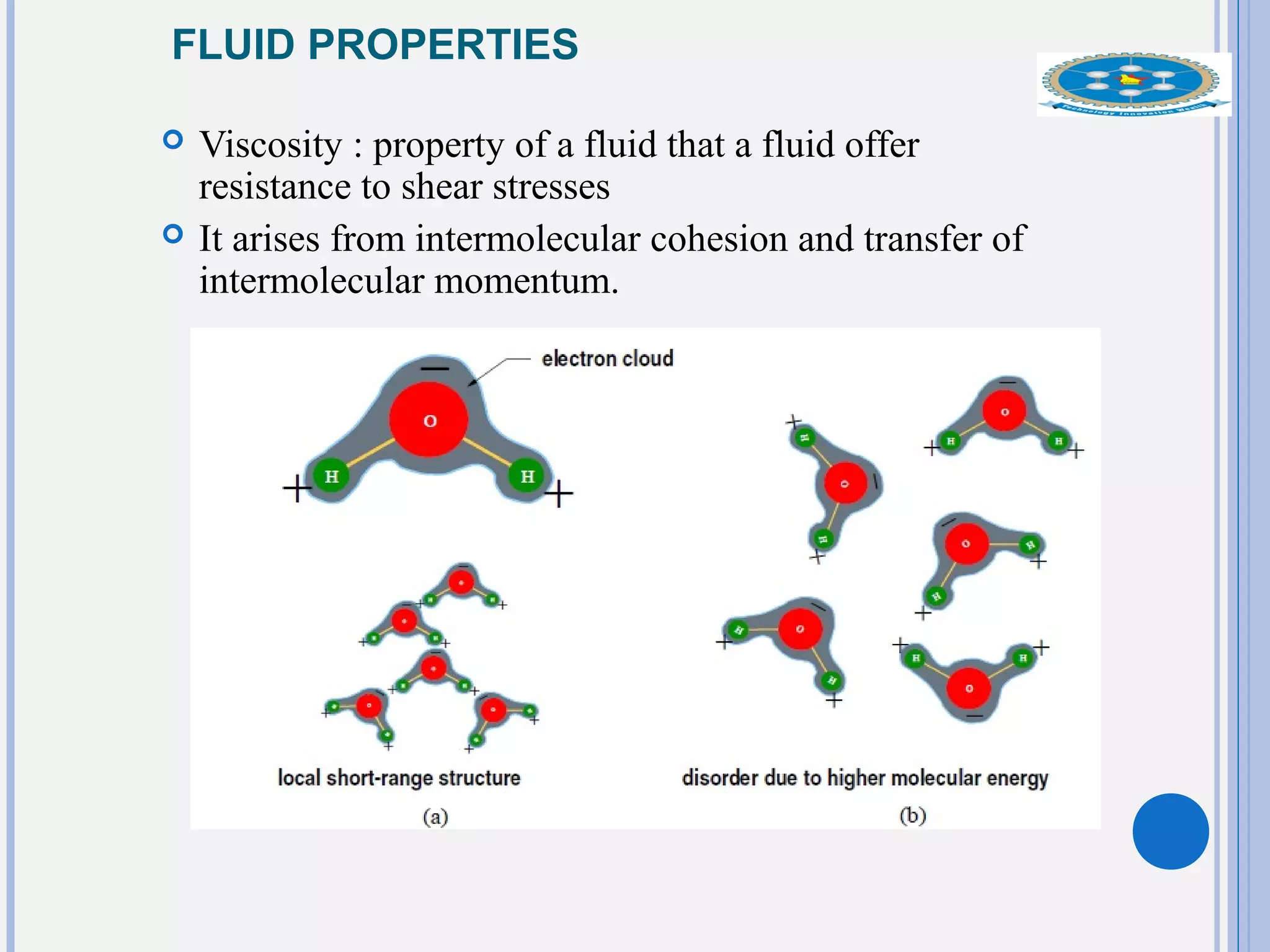
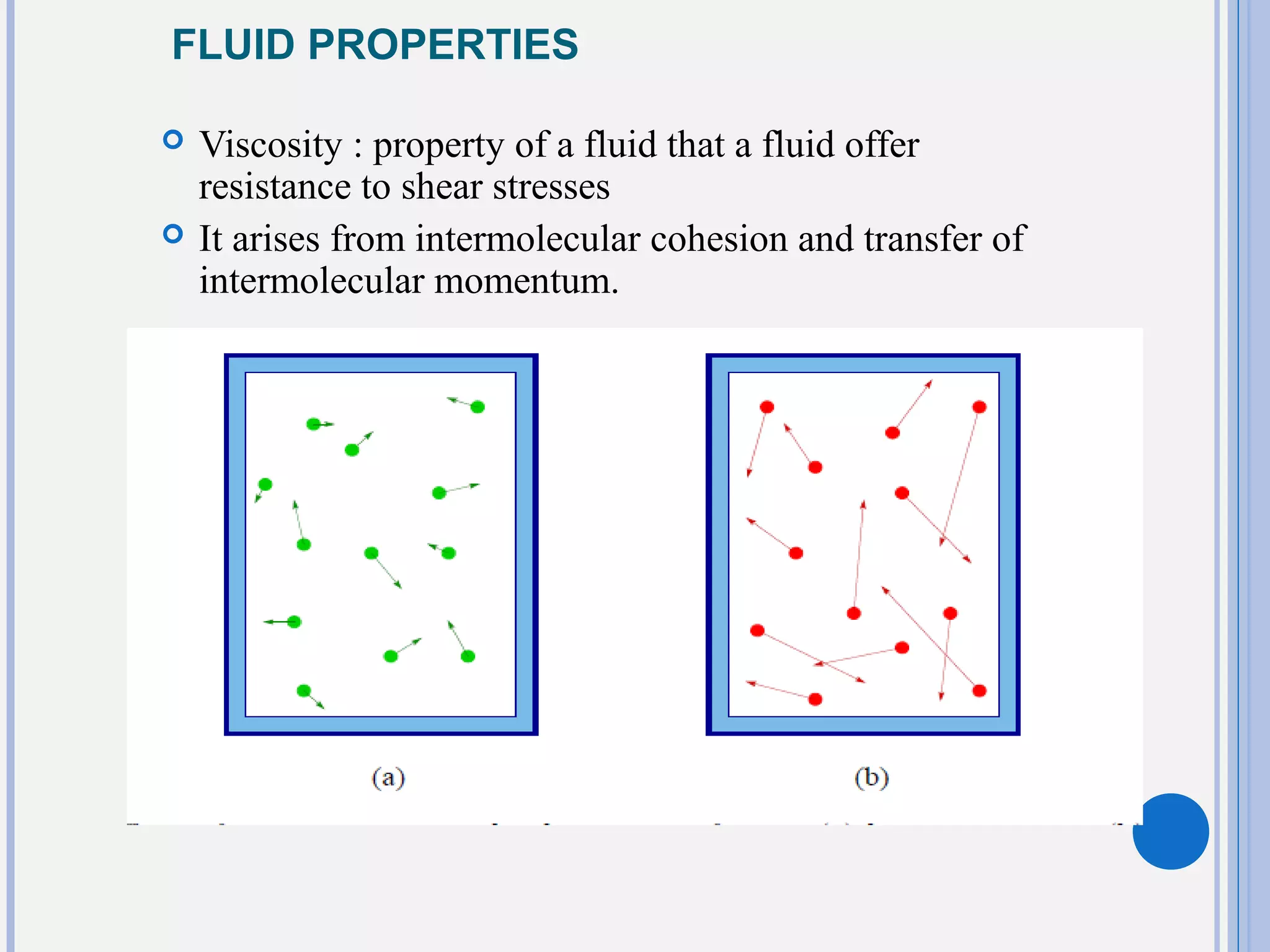


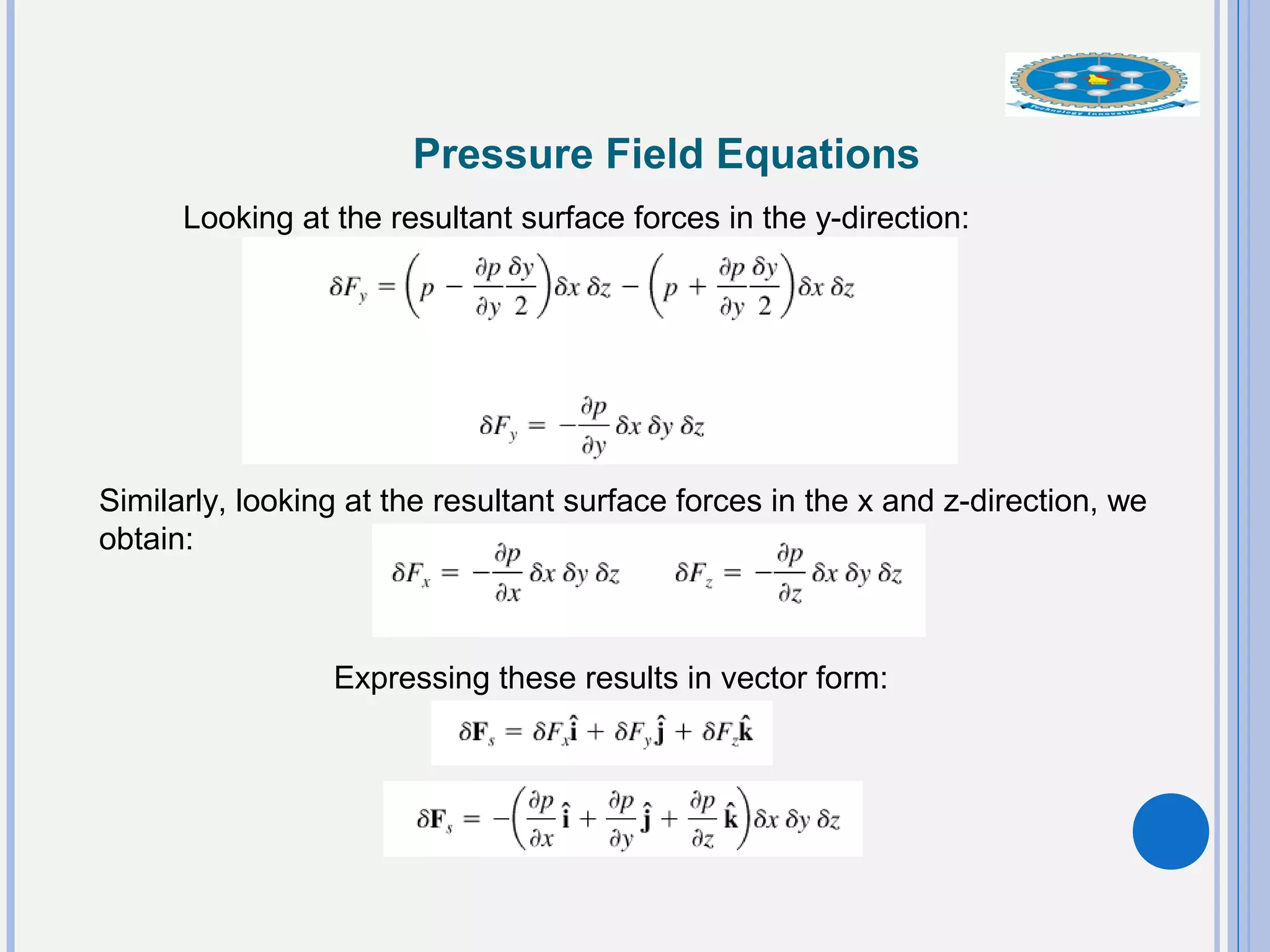


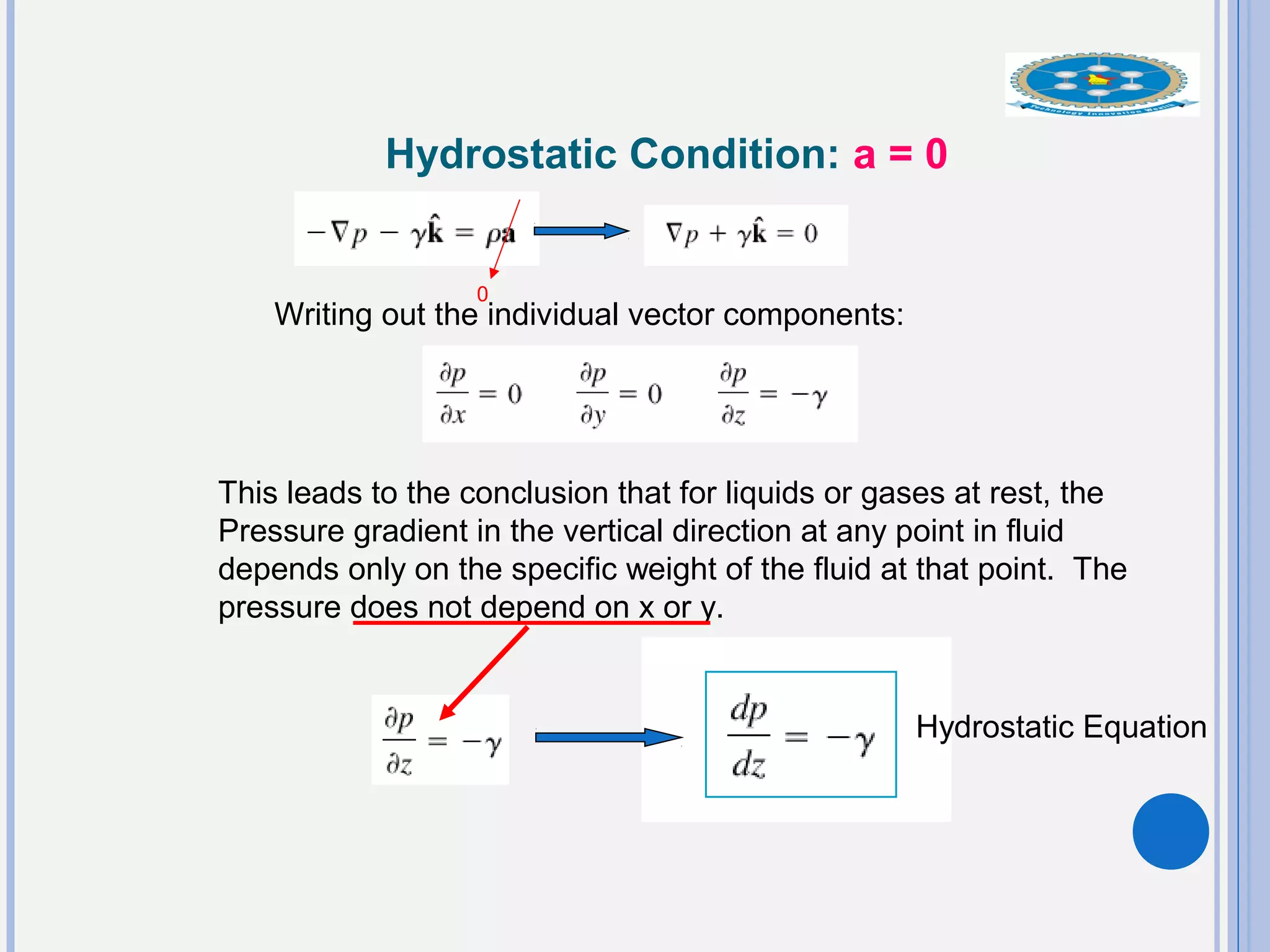
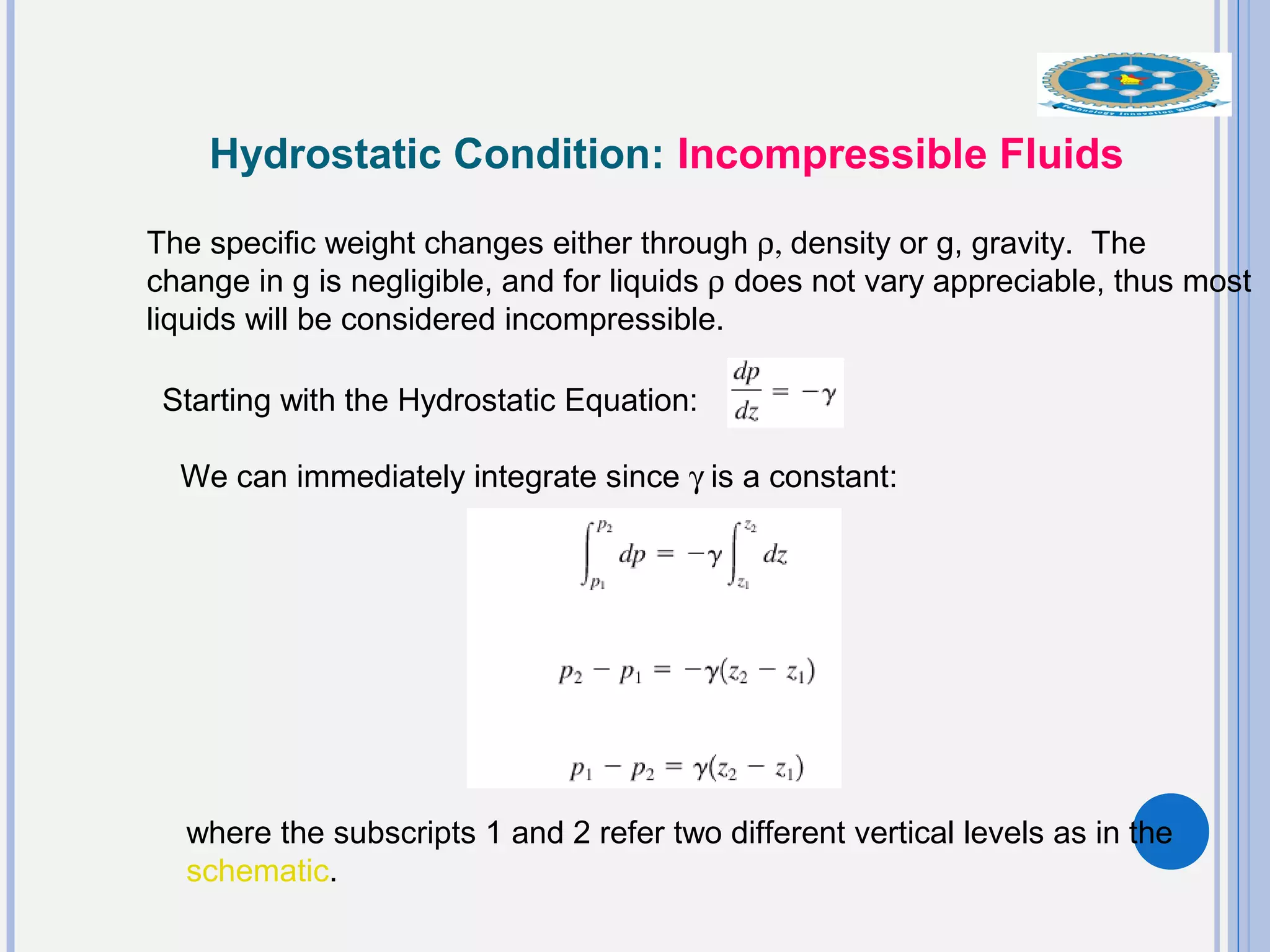


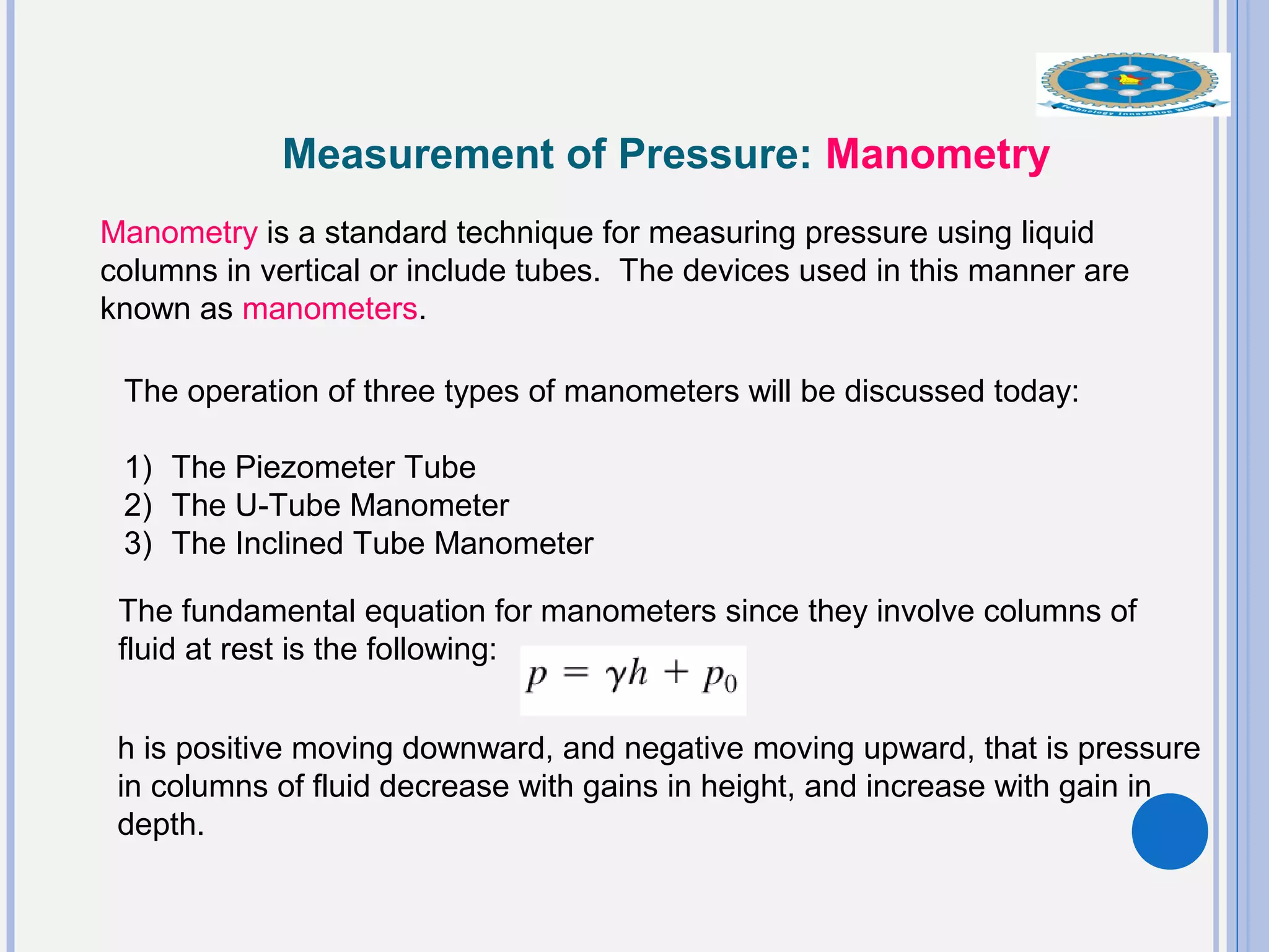
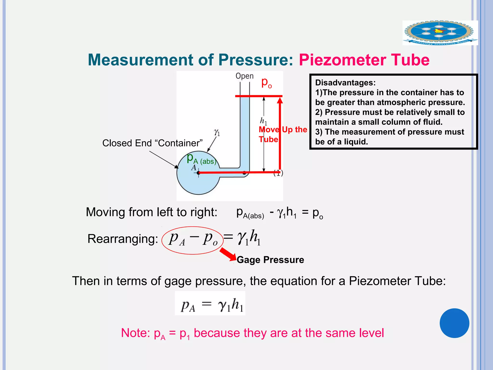


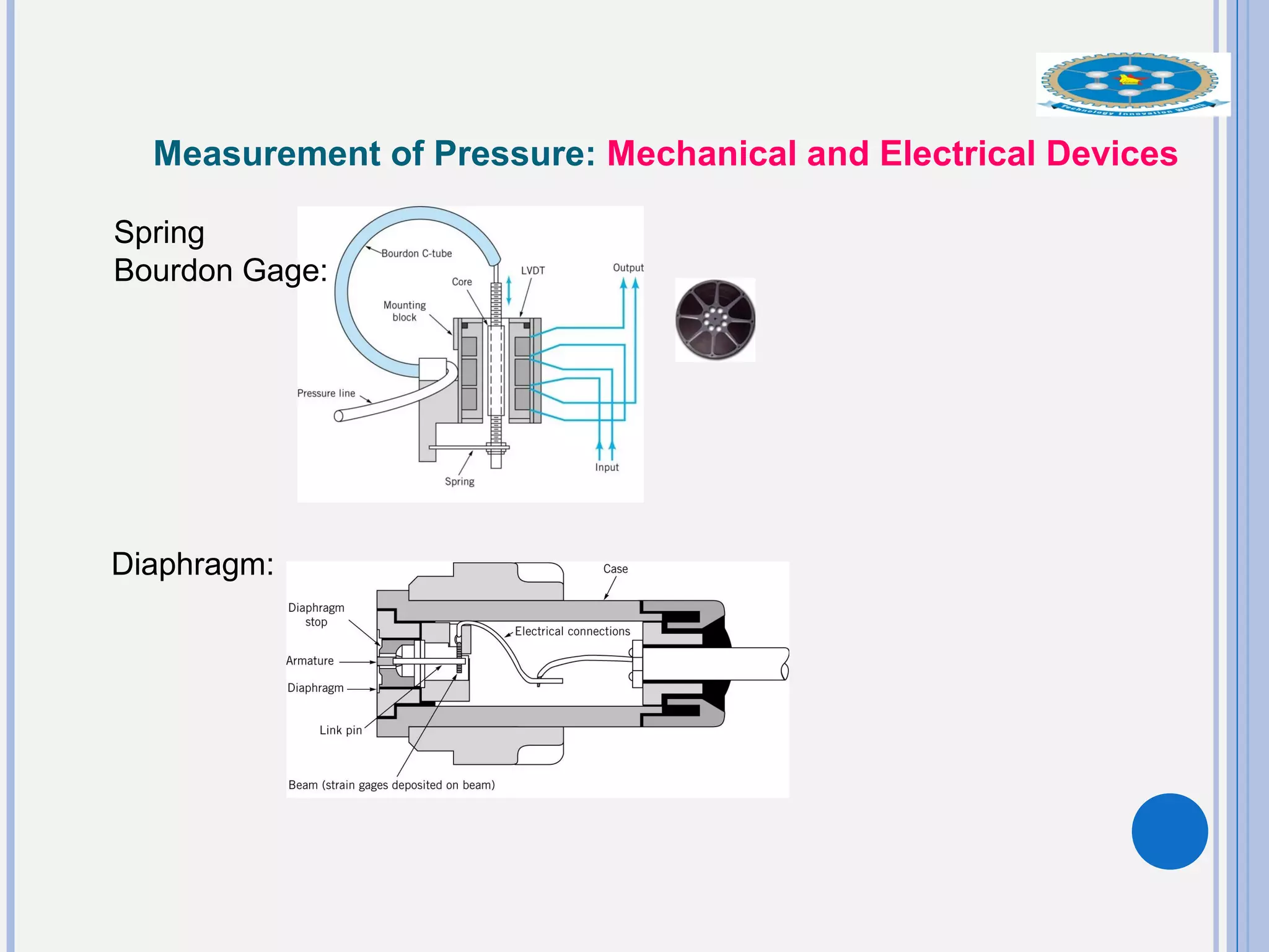


This document provides an overview of fluid statics and pressure measurements. It begins with defining key fluid properties like viscosity and continuum hypothesis. It then discusses pressure at a point using Pascal's law and basic equations for pressure fields. The hydrostatic condition of zero acceleration is examined, leading to equations for pressure variation in incompressible and compressible fluids. Standard atmospheric models and various pressure measurement techniques like manometers, barometers, and mechanical devices are also summarized. Example problems are provided to demonstrate applications of the fluid statics concepts.