This document provides comprehensive lecture notes on fluid mechanics, detailing the characteristics and properties of fluids, including their divisions into liquids and gases. It covers essential concepts such as density, viscosity, flow types, and dimensional analysis, along with units and conversion factors used in the study of fluids. Methods for analyzing fluid flow and the behavior of fluids under various conditions are also discussed.


![2
C H A P T E R 1
Fluid mechanics
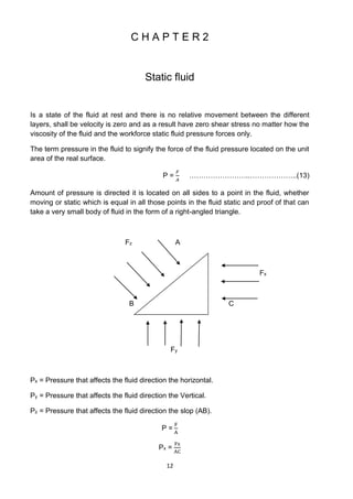
Fluid mechanics is a science in study the fluid of liquids and gases in the cases of
silence and movement and the forces acting on them can be divided materials found in
nature into two branches.
A- Solid Matters.
B-Fluid Matters:
Fluid material is divided into two parts:
1- Liquid Matters.
2- Gaseous Matters.
Fluid mechanics include fluid materials such as water, air and other while unique
science (Hydraulics) in the water as a liquid within the fluid material.
Hydrodynamics science is the study of the (Flow Fields) for materials may be not the
viscosity or compression or correlation but may even be a few special the weight
important and fluid called (Ideal fluid).
A fluid: is any substance that conforms the shape of its container and does not
permanently resist distortion. Gases, liquids and vapors are considered to have the
characteristic of fluids.
If a fluid affected by changes in pressure, it is called compressible fluid otherwise, it is
called incompressible fluid [1].
1.1 Units
The basic dimensions in fluid mechanics are below:
Property Symbol SI Unit English Unit
Force F N Ib
Length L m, cm Ft, in
Mass M Kg Slug
Time T S, min, hr S, min, hr
Temperature t Co Fo](https://image.slidesharecdn.com/lecturenotesinfluidmechanics-230129180316-82139207/85/Lecture-Notes-in-Fluid-Mechanics-2-320.jpg)
![5
Lean body mass Lbm = 454 gm
Ton = 1000 kg
Mass density (M/L3) Kg/m3 = 0.00194 slug/ft3
Weighted density ɣ (W/L3) = N.m3 = 0.006 Lbf/ ft3.
Ex.1: What all units of the system quantity:
1- Force 2- Pressure 3- Work 4-Power 5- Mass density.
Solution:
1- Force:
Force = Mass X Acceleration F = M x g F= M x Length/ time2.
2- pressure:
P = Force / area
3- Work:
W = F x Distance.
4- Power:
Power =
work
time
5- mass density:
ρ =
Mass
Volume
H.W: Find the units for viscosity, Sp.wt., pressure, mass, density.
1.3 Characteristics of flow and fluid property
1- mass density: or density [symbol: ρ (rho)]
It is ratio of mass of fluid to its volume.
ρ=
mass of fluid
volume of fluid
=
m
v
……………………..…………(1)
The common units used of density are kg/m3, g/cm3, Ib/ft3.
2- Weight density: or specific weight or: [symbol: (Sp. wt.)]
The ratio of weight of fluid to it is volume at standard temperature and pressure.
Sp. Wt. =
weight of fluid
volume of fluid
=
w
V
…………………………(2)
The common units used of density are
N
m3
,
dyne
cm3
,
Ib
ft3
.](https://image.slidesharecdn.com/lecturenotesinfluidmechanics-230129180316-82139207/85/Lecture-Notes-in-Fluid-Mechanics-5-320.jpg)
![6
The common weight density of water is 9.81
KN
𝑚3
.
Can express the relationship between the density of the equation: ɣ = ρ . g
Resulting from the Newton equation: (F = M . g). The use of the force of attraction
and accelerating (W= M. g) And dividing the parties to volume (W/V=M/V. g). We
get (ɣ=ρ. g).
3- Relative density:
is the ratio between the density of the material and the density of water at 4Co,
where the great water density under normal atmospheric pressure.
Relative density =
Density of the material
The density of water
………..…………(3)
4- Specific volume: [symbol: V]
The ratio of volume of fluid to it is mass. It is the reverse of mass density.
V =
Volume of fluid
Mass of fluid
……………………………….(4)
The common units used of density are
m3
kg
,
cm3
g
,
ft3
Ib
.
5- Compressibility
Is the portability size of the fluid to change the impact of external forces located
the fluid. Liquid its portability (Incompressibility). Gas its portability
compressibility to resize and reason is to the distances between the molecules
of the fluid.
6- Viscosity: resistance is carried out by the layers of the fluid to the external force.
That all of the fluid in nature has a viscosity resulting from fractions cohesion and
momentum exchange between the different layers of the fluid rises and these
fluids called fluid true or viscous fluid where the friction between the layers flow
when and where you get two cases of the flow:
A-laminar flow: Does not occurs blending.
B -turbulent flow: Occurs rotational blending between the fluid layers.
Ideal fluid: No viscosity they are not found in nature, but a portion of the fluid
viscosity is too small to the extent that it ignored in the calculations and the
viscosity of the types:
1- Dynamic viscosity: [symbol: µ (mu)] Dynamic viscosity: know is the shear stress
and speed slope
Change vilocity
Change distance
(
du
dy
).
µ=
Shear strain
Rate of shear strain
=
τ
du
dy
………………………..(5)
τ = µ.
du
dy
………………………………….(6)](https://image.slidesharecdn.com/lecturenotesinfluidmechanics-230129180316-82139207/85/Lecture-Notes-in-Fluid-Mechanics-6-320.jpg)
![7
shear strain: Is the force acting on a body fluid or solid in unit area of the body.
Shearing strain j =
f
A
,
force
area
……………………(7)
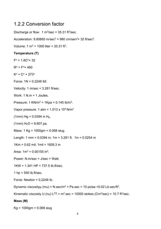
Viscosity of any fluid depends only on temperature. Vigorous and increases molecular
mixing, thus the viscosity, increases. In case of a liquid, we find that increasing. Its
temperature separates the molecules from each other, weakening. The attraction
between them so the viscosity decreases.
Thus, the relation between temperature and the viscosity is shown in figure below.
The relation between shear stress & velocity gradient (
du
dy
).
Consider a, fluid confined between two plats as shown in, figure below. Which are
situated at a very short distance (y) a part show in fig. the fluid motion is assumed to
take place in a series of infinitely then layers, free to slide one over the other is no
turbulence; the layer adjacent to the stationary plate is at rest while the layer adjacent to
the moving plate has a velocity (u).
F A
τ
u
L u
Oil
Where:
u: Velocity of the moving plate (varies linearly from at the stationary surface to maximum
at the contact surface between the moving plate and oil).
A: Contact area between the moving plate and oil.
F: Applied force to the moving plate.
L: Thickness of oil layer.
This expression for the viscous stress was first proven by Newton equation of viscosity.
Almost all fluids have a constant coefficient of proportionality and are referred to as
Newtonian fluids and the fluids that do not follow this law are non- Newtonian fluids. The
figure below shows these types of fluids.
2- Kinematic viscosity: [symbol: U (nu)]](https://image.slidesharecdn.com/lecturenotesinfluidmechanics-230129180316-82139207/85/Lecture-Notes-in-Fluid-Mechanics-7-320.jpg)
![8
The ratio of the dynamic viscosity to the fluid mass density.
U=
µ
ρ
=
M
L.T
.
L3
M
……………………….…………….(8)
The common units used of kinematic viscosity are (
m2
sec
,
cm2
sec
,
ft2
sec
, stoke).
m2
sec
= 10 stoke.
1.4 Flow Characteristics
The term flow Characteristics refers to a quantity that may change from one point to
another or from one space to another:
1- Shear stress: [symbol: τ (tau)]
It is the force per unit surface area that resists the sliding of the fluid layers.
The common units for shear stress are N/m2 = Pa, dyne/cm2.
2- Pressure: [symbol: P]
It is the force per unit cross sectional area normal to the force direction.
The common units used for pressure is N/m2 = Pa, dyne/cm2, atm, bar, psi,
The pressure difference between two points refers to (ΔP).
The pressure could be expressed as liquid height (or head).
Where: P = ρ.g.h and ΔP = ρ.g.Δh
h: is the liquid height or head, units (m, cm, and ft).
3- Velocity: [symbol: u]
is defined as average distance achieved for the time of units (
𝑚
𝑠𝑒𝑐
).
4- Discharge or Flow rate: [symbol: Q]
Discharge is the volume of fluid transferred per unit time.
Q = A. u where A: is the cross sectional area of the flow normal to the flow direction.
And the common units used for volumetric flow are m3/sec, cm3/sec, ft3/sec.
5- Force: [symbol: F]
Is all that is produced or is tries to produce or stop or change movement. Units
Newton, dyne. N = 100000 dyne.
6- Time: [symbol: T, t] the Units is second.](https://image.slidesharecdn.com/lecturenotesinfluidmechanics-230129180316-82139207/85/Lecture-Notes-in-Fluid-Mechanics-8-320.jpg)
![9
7- Acceleration: [symbol: g] is the Rate of change of speed per unit time, the Units
𝑚
𝑠𝑒𝑐2
.
1.5 Dimensional analysis
Is an important means of modern science of Fluid Mechanics is a field of mathematics
fields where deals with mathematics dimensions quantities.
The methods of dimensional analysis set out on the basis of Fourier for homogeneity
dimensional known since 1822, which show that the equation that express normal
relations between the quantities must be homogeneous and any that the dimensions of
the left side are the same dimensions right side, used to check the examples
mathematical through the dimensions of quantities required.
Analyses dimensional helps to know the way to get a lot of information from the
experiences of a few.
In order to clarification the steps we take one sporting equations, but the expressive
power equation on the surface in a liquid consonant.
F = ɣ. h. A ………………………….……………..(9)
assume that the dimensions of the specific weight and height and area known and
unknown dimensions of force.
The dimensions of the force made up of mass, length and time can be know from the
equation.
F = M. L / T2 ……………………………………..(10)
Dimensions (F) = Dimensions(ɣ). Dimensions(h). Dimensions(A).
M1. L1. T-2 = (ML-2T-2). (L1). (L2) ……………………………..(11)
Where the unknowns are (a, b, c).
If applied to the base of the homogeneity analysis ^ basic be conform on each side of
the equation.
a= 1, b= -2 + 1 + 2 = 1, c= -2.
So, the Dimensions (F) Equals.
M1. L1. T-2 = ML/T2
Equal to the force that can be the directly simplification and without mathematical
operations, but what work above is the usual way to get dimensional information for any
amount.
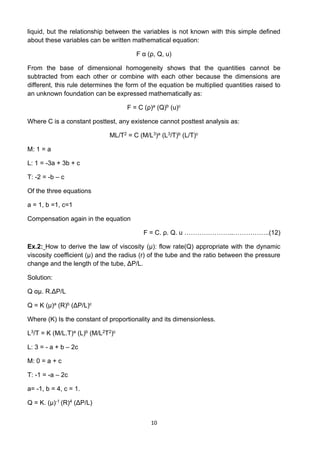
Another example of the solution assumes the force that can be received from the
circular hole depends on the flow rate Q and average speed u and mass density of the](https://image.slidesharecdn.com/lecturenotesinfluidmechanics-230129180316-82139207/85/Lecture-Notes-in-Fluid-Mechanics-9-320.jpg)
![16
with the inner tube to get the correct reading. It may be the pressure in the pipe or tank
High, improves the use of heavy liquid such as mercury, for example in Manometer to
avoid excessive for Manometer [2].
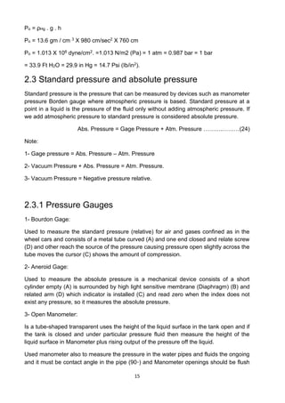
Ex.5: Measured pressure fluid tank by manometer simple open and be shaped (U) and
connect tank containing fluid to be measured pressure is being fluid in the tube and
touching mercury in manometer and the advantage of mercury high and specific weight
is calculated pressure after it gets balance level liquid ends of manometer and at (a - a).
Solution:
Patm
Tank A
h1 h2
a a
Hg
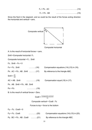
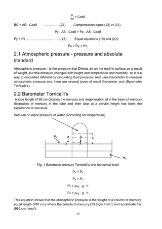
P =
F
A
=
W
A
=
M .g
A
P =
M
V
.V .g
A
=
ρ .A .h g
A
P = ρ . g . h Since the pressure at a level equal (a-a)
PA + ρA . gh1 = Patm + ρHg . gh2
PA = Patm+ ρHg . gh2 – ρA . gh1
Ex.6: Monometer normal simple open pressure when (A) less than atmospheric
pressure (unstable).
Patm
Tank A
Hg
a a
Solution:
At the level of (a-a) equal pressure.
1
h
2
h](https://image.slidesharecdn.com/lecturenotesinfluidmechanics-230129180316-82139207/85/Lecture-Notes-in-Fluid-Mechanics-16-320.jpg)
![20
C H A P T E R 3
Fluid flow
In this chapter we take the movement of fluids and the forces that affect them and cause
the flow, and depends on the laws of fluid dynamic, is:
1. Conservation of Mass: the law of conservation of mass (continuity equation
represents).
2. Conservation of Energy: Energy Conservation Act (representing the Bernoulli
equation).
Law of conservation of mass (mass not perish not born out of nowhere) This represents
the flow of fluid in the pipe or the wind etc..
3.1 Conservation of Mass
Mass Flow rate (mo): is quantity fluid flow through the unit time through the tube section
or surface.
The unit of mass flow rate in (SI) unit (Kg/sec), (g/sec).
Flow rate depends on the density and speed of the fluid passing the tube section,
whenever the velocity or density or sectional area of the pipe increased flow rate.
The flow rate of the fluid = velocity X density X sectional area of the pipe [3].
mo = ρ . u . A ……………………….………..(28)
Since the circular tube section, the cross-section area equal to the square radius:
A =
𝜋
4
. d2
mo = ρ . u . (
𝜋
4
. d2)
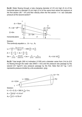
Ex.13: Find mass flow rate water in units (kg/min) flowing in a pipe diameter of 10 cm
and velocity 1 (
m
sec
).
mo = ρ . u . A
mo = 1000
Kg
m3
X 1
m
sec
X
π
4
(
10
100
)2
mo = 7,85
Kg
sec
= 471
Kg
min
3.1.1 Flow rate (Q)
Is the volume of the fluid through the unity of time and used in the case of more fluid
because the density of the liquid nearly constant with temperature change and pressure,](https://image.slidesharecdn.com/lecturenotesinfluidmechanics-230129180316-82139207/85/Lecture-Notes-in-Fluid-Mechanics-20-320.jpg)
![28
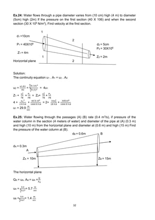
Ex.21: Find the ratio between my velocity gas pipe variable diameter if the pipe diameter in
the first section (2m) and when the second section (3m) and pressure in the first section (90
N/m2) In the second section (40 N/m2), either the temperature in the first section was (200
⸰F) and the second section (150 ⸰F).
Solution:
𝑢2
u1
=
𝑃1
P2
.
𝑇2
T1
.
𝐴1
A2
𝑢2
u1
=
90
40
.
150+460
200+460
.
π
4
X 22
π
4
X 32
𝑢2
u1
=
61
66
= 87.46
3.3.2 Fluid energy (Conservation of energy)
Energy cannot perish but transformed from one form to another equation that we get by
using this law called energy or Bernoulli equation, take different forms depending on the type
and the fluid flow and dimensions used in the analysis.
Types of energies that lead to the movement of fluids. Energy generally known as the
susceptibility to achievement work and divided into:
1 - Potential energy (Ez): This type of energy is produced often from the effect of the power
of gravity, for example, we find that the water stored in tanks high even have adequate
capacity for flow in pipelines for distribution, and downhill car from the top of the slope to the
bottom without running the engine powered underlying Depends on body mass and height
for a certain level [4].
Ez = M . g . Z ………………………..……………….(34)
2 - Energy Pressure (Ep): Energy is those owned liquid molecules as a result of pressure If
the mass of the fluid pressure (P), and density (ρ).
Ep =
𝑃 . 𝑀
ρ
= P . V
V = volume of the fluid directed pressure admitted to the system to get work.
3. Kinetic energy: Kinetic energy: is energy consisting of body mass (M) movement depends
on the velocity (u).
Eh =
1
2
M. u2 ………………………..………………(35)
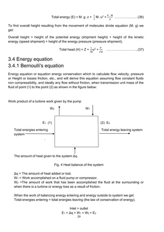
All energies measured in units of (force * Distance), (N. M) and is called the Joule. The total
energies of fluid particles in motion equal to the potential energy and kinetic energy and
pressure energy.](https://image.slidesharecdn.com/lecturenotesinfluidmechanics-230129180316-82139207/85/Lecture-Notes-in-Fluid-Mechanics-28-320.jpg)
![30
E2 – E1 = Δq + W1 + W2
Since the fluid is ideal (no friction)
There are no Add and there is no drag of the temperature of the system. (Δq = 0)
There is no pump or compressor. W1 = 0
E2 – E1 = 0 …………………………………..……(38)
Where (E1) (E2) are Total of the energies of the molecules of the fluid at the point (38)
and (36) are entering the system and leaving the system and which have been collected
at one equation:
E = M. g. z +
1
2
M. u2 +
P . M
ρ
Substitute equation (2) in (1) we get:
[M. g. z2 +
1
2
M. u2
2 +
P2 . M
ρ
] - [M. g. z1 +
1
2
M. u1
2+
P1 . M
ρ
] = 0
And dividing the equation (M. g) we get:
[Z2 +
1
2g
. u2
2 +
P2
ρg
] - [Z1 +
1
2g
. u1
2+
P1
ρg
] = 0
Z1 +
u1
2
2g
+
P1
ρg
= Z2+
u2
2
2g
+
P2
ρg
Or [ΔZ +
Δu2
2g
+
ΔP
ρg
] = 0
This equation is called the Bernoulli equation.
ΔZ = Height product (Height shipment).
Δu2
2g
= Velocity height, (shipment velocity).
ΔP
ρg
= Pressure head, (shipment Pressure).
3.4.2 Limitation of Bernoulli's equation
1 - the speed of each liquid molecules cross-section tube be regular.
2 - not the effect of external forces, except for the effect of gravity on the liquid.
3 - not part of the energy loss during the flow of the liquid.
4 - If the flow of fluid through a curved path when it should be calculated the loss of
energy as a result of centrifugal forces, and this is when using the Bernoulli equation [5].
Application examples of the Bernoulli equation:](https://image.slidesharecdn.com/lecturenotesinfluidmechanics-230129180316-82139207/85/Lecture-Notes-in-Fluid-Mechanics-30-320.jpg)
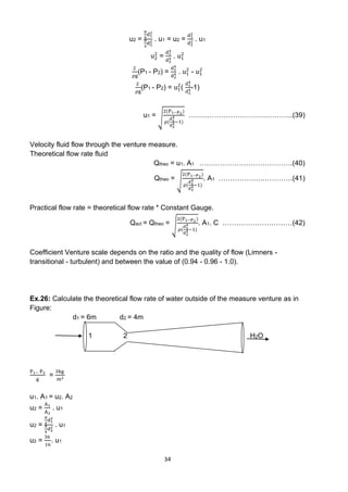
![33
ZA +
uA
2
2g
+
PA
ρg
= ZB+
uB
2
2g
+
PB
ρg
10 +
5.72
2 X 9.8
+
ρghA
1000 X 9.8
= 15+
1.42
2X 9.8
+
PB
1000 X 9.8
𝑃𝐵
𝜌𝑔
= 0.6 mH2O PB = 5880
N2
m
3.4.3 Bernoulli's equation applications
The basic equation of Bernoulli equation has many applications in fluid movement and
the most important of these applications:
1- Venturi meter.
2- Orifice meter.
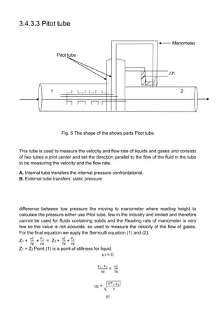
3- Pitot tube.
4- Measuring the velocity of the liquid flow of a circular hole in the tank.
5- Bernoulli's equation when there is a pump.
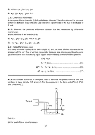
3.4.3.1 Venturi meter
Used to measure the flow rate of the liquid which consists of the following parts:
a - Convergent cone:
Is a short pipeline starts from the tube diameter associated with (d1) and take its walls
convergent to the small diameter (d2).
b - Throat
The walls are parallel and have a diameter equal to (d2) and constant.
3 - Divergent cone
Is the last part of the measure you take walls divergent the diameter (d2) to diameter
(d1), have a length of about (3-4) weaken length of the cone of convergence, when the
flow of fluid through the scale of the first section (d1) to the second section (d2) during
the convergence cone, As a result accelerate the liquid increases flow velocity at (d2)
and this increase quickly lead to a decrease in pressure, there is fixed ratio are relying
upon between (d1/d2) and preferably be (1/3) (1/2) until you get to read a set of column
manometer not get other problems, after the arrival of the liquid to the last section (cone
spacing) less speed and pressure and increases rapidly when decries the lead to break
the course of this fluid works spacing along the cone (3-4) times the length of the cone
of convergence as well as to reduce the loss due to friction [6].
To find a formula to measure the flow rate in this measure apply Bernoulli's equation
when the colon (1) (2) in the scale in its horizontal so that it is equal height (Z1 = Z2) we
get:
Z1 +
u1
2
2g
+
P1
ρg
= Z2+
u2
2
2g
+
P2
ρg
P1− P2
ρg
=
u2
2−u1
2
2g
2
ρg
(P1 - P2) = u2
2
-u1
2
u1. A1 = u2. A2
u2 =
A1
A2
. u1](https://image.slidesharecdn.com/lecturenotesinfluidmechanics-230129180316-82139207/85/Lecture-Notes-in-Fluid-Mechanics-33-320.jpg)
![35
Z1 = Z2
P1− P2
g
=
u2
2−u1
2
2g
3
kg
m2
1000
kg
m3
=
1
2x9.8
(
362
162
. u1
2
- u2
2
)
u1 = 0.12
m
sec
Qtheo = u1. A1
Qtheo =
π
4
(6)2 X 0.12
Qtheo = 3.4
m3
sec
Ex.27: Calculate the height of a column of mercury in manometer linked measure
Venturi horizontal the situation which diameter entrance (160 mm) diameter necked (80
mm) and being through which oil and weight Specific (0.8) knowing that constant
measure (C = 1) and the rate of oil flow practical (50 liters /seconds).
d1 = 160mm d2 = 80mm
1 2 H2O
h
Hg
A1 =
π
4
d1
2
=
π
4
(
160
10
)2 = 201.06 cm2
A2 =
π
4
d1
2 = π
4
(
80
10
)2 = 50.26 cm2
Qact = 50
lit
sec
X
1
1000
m3
lit
X
(100cm)3
m3
= 50 X103 cm3
lit
Qact = C.Qtheo
Qtheo = C.A √
2△P
⍴[(
A1
2
A2
2)−1]
50 X103= 1 X 201.06 √
2△𝑃
0.8[(
201.062
50.262 )−1]
△P = 3.7 X 10⁵ 𝑑𝑦𝑛𝑒
𝑐𝑚2
△P = ⍴Hg.g.h
h =
3.7 𝑋 105
13.6
𝑔
𝑐𝑚3𝑋 980 𝑐𝑚/𝑠𝑒𝑐2
= 27.8 cm Hg](https://image.slidesharecdn.com/lecturenotesinfluidmechanics-230129180316-82139207/85/Lecture-Notes-in-Fluid-Mechanics-35-320.jpg)
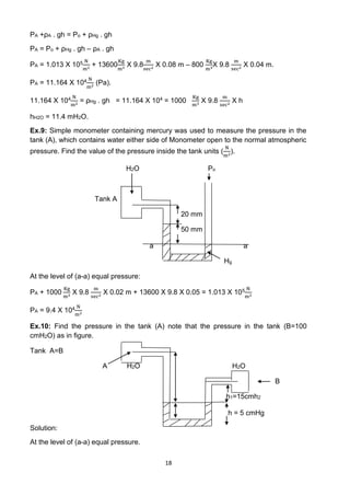
![36
3.4.3.2 Orifice meter
Advantage of this measure accuracy and simplicity and ease of installation and
maintenance and low cost, which is a plate with a small hole at its center, is placed in
the course of the fluid and the hole narrow lead to an increase in the velocity of the fluid
(according to the equation of continuity), leading to reduced pressure (according to
equation Bernoulli) and is measuring pressure by manometers the links between the two
points (1) and (2) to obtain the final the equation of continuity same the derivation
measure of Venturi by applying Bernoulli's equation and the continuity equation:
Qact= C.A √
2△P
⍴[(
D1
4
D2
4)−1]
……………..……………….(43)
Value of the constant is different in this measure, ranging from 0.61 - 0.62, and
sometimes to 0.65 depending on the type and flow according to the ratio
D2
D1
.
O Orifice plate
1 2
Manometer
h
Fig. 5 The shape of the shows parts measure of orifice
Ex.27: Calculate the flow rate of oil the practical (density 0.8 g/cm3) through a tube
diameter (20 cm) contains on Orifice plate diameter (10cm) (C=0.64) the read
manometer (10 mmHg).
d1 = 20 cm d2 = 10cm P1-P2 = ⍴gh C=0.64
Qact= C.A √
2△P
⍴[(
D1
4
D2
4)−1]
Qact = 0.64 X π/4(20)2 X√
2(13.6 X 980 X 10)
0.8[(
204
104 )−1]
Qact = 9461 cm3/sec](https://image.slidesharecdn.com/lecturenotesinfluidmechanics-230129180316-82139207/85/Lecture-Notes-in-Fluid-Mechanics-36-320.jpg)
![38
This equation is used to measure the velocity of the flow rate gas by Pitot tube, and to
calculate the flow rate theoretical = velocity X area Section of the tube [7].
Qtheo = u2.A2
Qtheo= A2 X √
2(P1−P2)
ρ
Qtheo = Qact
C = 1
Ex.28: Pitot Tube is used to measure the velocity of the flow of kerosene density (0.8
g/cm3) The read manometer (5 cmHg). Calculate the velocity u2 = √
2(P1−P2)
ρ
, u2 =
√
2(5 X 13.6 X 980)
0.8
= 182.5 cm/sec.](https://image.slidesharecdn.com/lecturenotesinfluidmechanics-230129180316-82139207/85/Lecture-Notes-in-Fluid-Mechanics-38-320.jpg)
![39
C H A P T E R 4
Real fluid flow and pressure loss in pipes
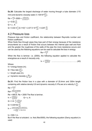
4.1 Reynolds number (Re)
Reynolds Number of a flowing fluid obtained by dividing the inertia force of the fluid
(velocity X diameter) into the kinematic viscosity (viscous force per unit length).
Re =
u.d
ν
=
ρ.u.d
μ
……………….………………(44)
Where:
d =diameter of flow section (m).
ν = kinematic viscosity (
m3
sec
).
ρ= Mass density of fluid (
kg
m3).
μ = dynamic velocity of fluid (
N.sec
m2 ). or (Pa. sec).
4.1.1 Types of flow
A. Laminar flow
This type of flow when the flow rate is slowly and velocity at any fixed point does not
change with time.
B. Turbulent flow
This type of flow when the flow rate is high and the speed at any point variable with time
and equal to the velocity [8].
Note:
We can find the flow of the fluid laminar flow or turbulent flow or transitional flow
according to Reynolds number, we depend on the following:
1- Laminar flow: Re ≤ 2000.
2- Transitional flow: 2000<Re<3000.
3- Turbulent flow: Re≥3000.
Ex.29: Determine the type of flow in a pipe with a diameter of (25.4mm) containing with
relative density (0.9) and dynamic viscosity (0.1Pa.sec) at a velocity (3
m
sec
)?
Re =
ρ.u.d
μ
Re
3X0.0254X900
0.1
Re = 685.6. Re < 2000The flow is laminar.](https://image.slidesharecdn.com/lecturenotesinfluidmechanics-230129180316-82139207/85/Lecture-Notes-in-Fluid-Mechanics-39-320.jpg)
![42
C H A P T E R 5
Pipes and valves
5.1 Pipe
Pipe is one of the transfer of liquids and gases. In chemical plants must transfer a lot of
liquids and gases, so it cannot dispense pipes, in addition to the solid material can be
transferred dust. General Pipe systems consist of a cylindrical pipe of circular section,
where it has compared to piped box-section [9].
Provides the correct conditions in the cylinders with the following circular
section:
1 - Less than the thermal Stream loss.
2 - high resistance.
3 - In an economic Production.
Before the construction of pipeline systems should provide the following:
1 - Type of material to be transferred to this system.
2 - The amount of material.
3 - Pressure in the system.
4 - Temperature.
5.1.1 Pipe industries
Pipe Industries used in the transfer of crude oil are steel pipes made of open hard steel
like electric steel furnaces.
5.1.2 Mainstream continuity equation
Q = u. A
Q =
m
⍴
………………….………………………(46)
Q = Volumetric mainstream transferred material.
m = The amount of material transferred per unit time.
⍴ = Density transferred material.
A = Section of the pipeline area.](https://image.slidesharecdn.com/lecturenotesinfluidmechanics-230129180316-82139207/85/Lecture-Notes-in-Fluid-Mechanics-42-320.jpg)
![44
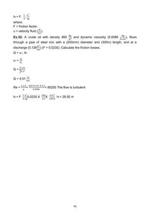
Ex.33: Pipe transfer of kerosene was designed flow rate of kerosene (12
cm3
sec
) and the
velocity of the passage of kerosene in the tube (1.5
cm
sec
) Calculate the outer diameter of
the tube and the tube of steel.
dr = √
4 .𝑄
𝜋 .𝑢
dr = √
4 𝑋 12
𝜋 𝑋 1.5
= 3.56 cm
dr = 35.6 mm
Nominal dimension from the table = 40
External diameter(de) from the table = 48.3 mm.
5.3 Types of pipes for the metal inside in its industry
1- Steel pipe: high-pressure-resistant and have a good ability to form and can be
transferred effect weak materials such as water and air.
2- Cost irons: of those pipes are made in the case of underground transport because
it has the ability to resist corrosion, and this kind be heavy and expensive at the
same time, the transfer of materials used acidic, and it is difficult to form these
tubes.
3- Plastic pipe: often used PVC pipe and be corrosion resistant and easy to operate
when heated and can be welded as well as paste them. Because of the high
resistance to corrosion fit used for the transport of gases severe reaction. Adverse
impact resistance, mechanical low temperatures [10].
5.4 Valves
Valves by which is controlled by opening and closing the gates, as well as to control the
flow of liquids and gases in the Pipe.
5.4.1 The most important purposes of valves
1- Allow total and total stop of the flow.
2- Amend flow.
3- Prevent flow in the adverse the trend.
4- Safety valve.
5.4.2 Type of valves
1- Gate valve.
2- Plug valve.
3- Diaphragm valve.
4- Ball valve
5- Globe valve.
6- Butterfly valve.
7- Check valve.
8- Safety valve.](https://image.slidesharecdn.com/lecturenotesinfluidmechanics-230129180316-82139207/85/Lecture-Notes-in-Fluid-Mechanics-44-320.jpg)