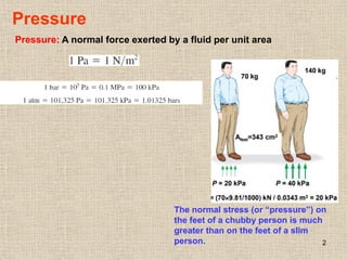
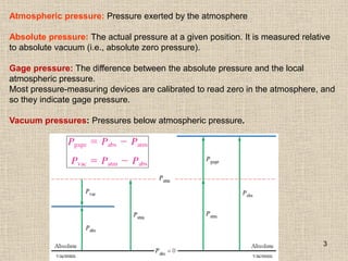
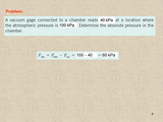
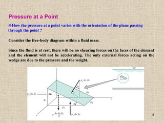
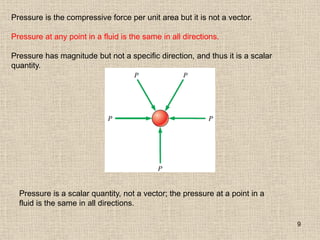
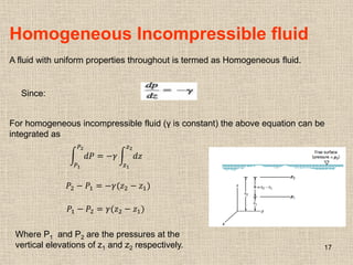
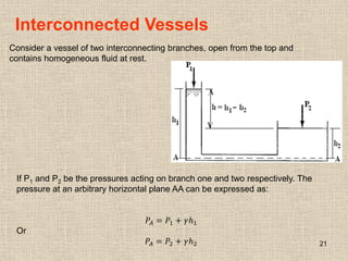
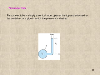
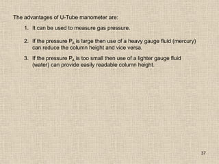
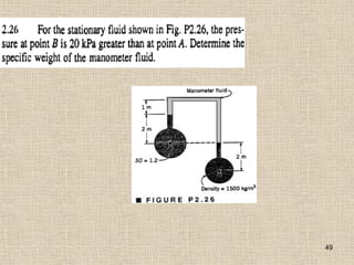
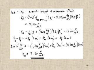
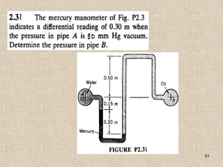
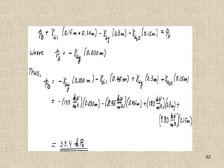
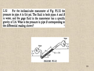
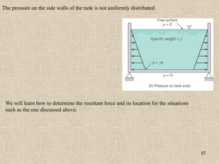
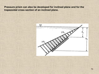
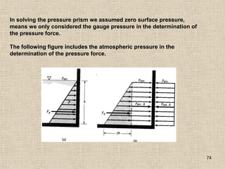
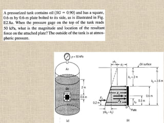
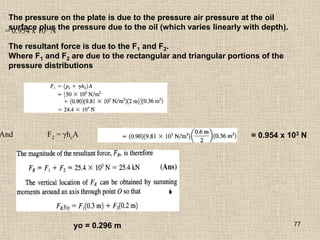
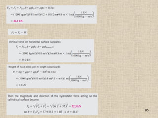
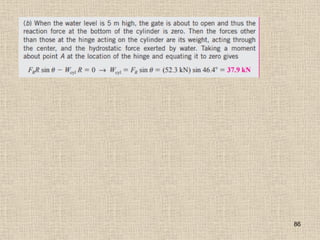
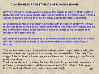
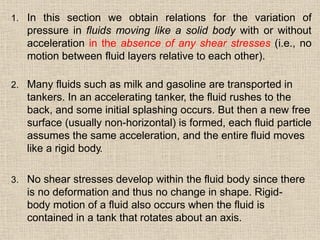
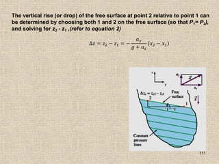
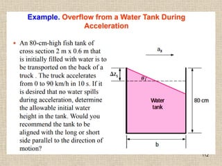
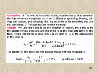
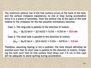
The document discusses pressure and fluid statics. It defines pressure as a normal force exerted by a fluid per unit area. Atmospheric pressure is the pressure exerted by the atmosphere, while absolute and gauge pressures are defined in relation to a vacuum. Pressure at a point in a fluid is independent of direction and is a scalar quantity. The pressure in a stationary, incompressible fluid varies with depth due to gravity and can be calculated using equations that take into account fluid density and height. Pressure also varies with temperature for compressible fluids like gases based on the ideal gas law and assumptions about temperature changes over altitude. Standard atmospheric models and various pressure measurement techniques are also covered.

![107
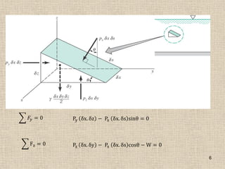
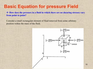
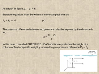
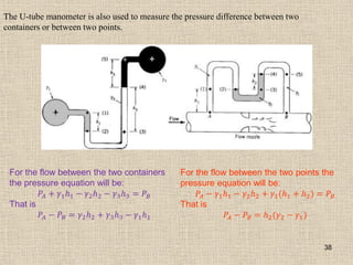
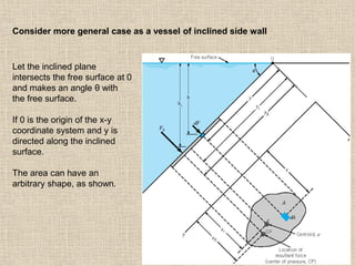
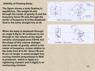
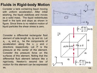
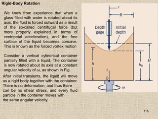
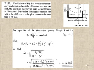
Fluids in Rigid-body Motion
𝐹𝑧 = 𝑚𝑎𝑧 𝑃 −
𝜕𝑃
𝜕𝑧
𝑑𝑧
2
𝑑𝑥𝑑𝑦 − 𝑃 +
𝜕𝑃
𝜕𝑧
𝑑𝑧
2
𝑑𝑥𝑑𝑦 − 𝜌𝑔 𝑑𝑥𝑑𝑦𝑑𝑧 = 𝜌 𝑑𝑥𝑑𝑦𝑑𝑧 𝑎𝑧
−
𝜕𝑃
𝜕𝑧
𝑑𝑥𝑑𝑦𝑑𝑧 − 𝜌𝑔 𝑑𝑥𝑑𝑦𝑑𝑧 = 𝜌(𝑑𝑥𝑑𝑦𝑑𝑧)𝑎𝑧
𝜕𝑃
𝜕𝑧
= −𝜌(𝑔 + 𝑎𝑧)
Similarly, the net surface forces in x- and y- directions are
𝜕𝑃
𝜕𝑥
= −𝜌𝑎𝑥 ;
𝜕𝑃
𝜕𝑦
= − 𝜌𝑎𝑦
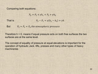
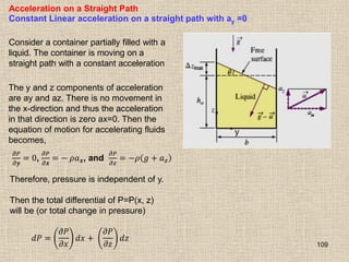
Special Case 1: Fluid at Rest
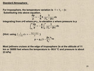
For fluid at rest or moving on a straight path at constant velocity, all components of
acceleration are zero, therefore,
𝜕𝑃
𝜕𝑥
= 0 ,
𝜕𝑃
𝜕𝑦
0 , 𝑎𝑛𝑑
𝜕𝑃
𝜕𝑧
= −𝜌𝑔
Which confirm that, in fluids at rest, the pressure remains constant in any horizontal
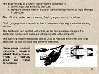
direction (P is independent of x and y) and varies in the vertical direction as a result
of gravity [ and thus P=P(z)]. These relations are applicable for both compressible
and in compressible fluids.](https://image.slidesharecdn.com/2-240405183211-4f9d0d47/85/2-Chapter-2-Pressure-Fluid-Statics-FM1-Complete-pdf-107-320.jpg)
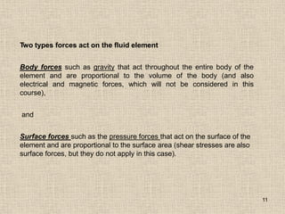
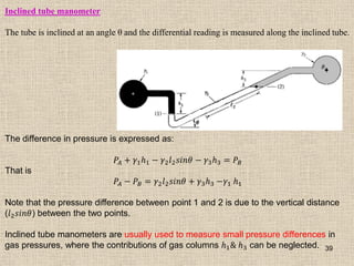
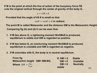
![108
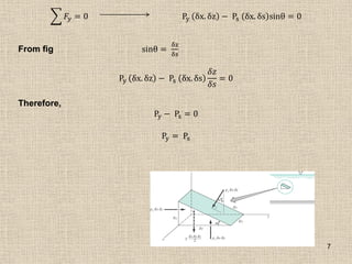
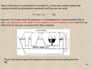
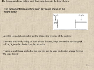
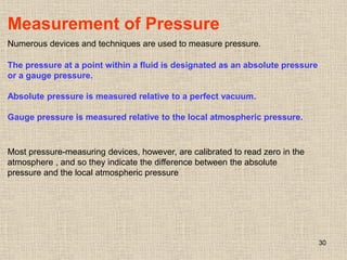
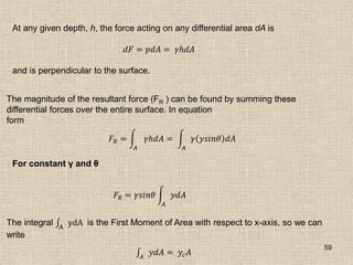
Special Case 2: Free Fall of a Fluid Body
A free falling body accelerates under the influence of gravity. When the air resistance
is negligible, the acceleration of body equals the gravitational acceleration and
acceleration in any horizontal direction is zero. Therefore, ax = ay =0 and az = -g.
Then the equations of motion for accelerating fluids becomes,
Free falling ;
𝜕𝑃
𝜕𝑥
=
𝜕𝑃
𝜕𝑦
=
𝜕𝑃
𝜕𝑧
= 0
[
𝜕𝑃
𝜕𝑧
= −𝜌 𝑔 + 𝑎𝑧 = −𝜌 𝑔 − 𝑔 = 0]
Therefore, in a frame of reference moving the fluid, it behaves like it is in an
environment with zero gravity. Also, the gage pressure in a drop of liquid in free fall
is zero throughout. (Actually the gage pressure is slightly above zero due to surface
tension which holds the drop intact).
For example, the pressure throughout a “blob” of orange juice floating in an
orbiting space shuttle (a form of free fall) is zero. The only force holding the liquid
to gather is surface tension.
When the direction of motion is reversed and the fluid is forced to accelerate
vertically with az = +g by placing the fluid container in an elevator or a space
vehicle propelled upward by a rocket engine, the pressure gradient in the z-
direction is
𝜕𝑃
𝜕𝑧
= −2𝜌𝑔. Therefore, the pressure difference across a fluid layer now
doubles relative to the stationary fluid case.](https://image.slidesharecdn.com/2-240405183211-4f9d0d47/85/2-Chapter-2-Pressure-Fluid-Statics-FM1-Complete-pdf-108-320.jpg)


![Plumbing_services [Dr. Kamakshi Memorial Hospital].pptx](https://cdn.slidesharecdn.com/ss_thumbnails/plumbingservicesdr-231001055202-fbb14ec4-thumbnail.jpg?width=640&height=640&fit=bounds)


