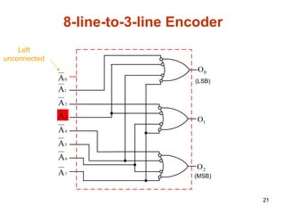
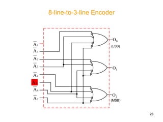
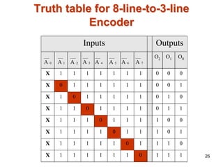
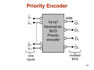
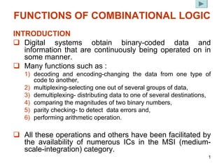
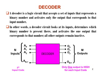
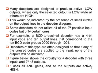
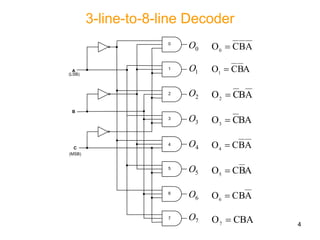
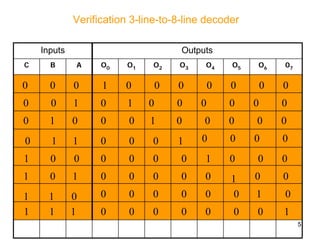
This document discusses various combinational logic functions including decoding, encoding, multiplexing, and decoding. It provides details on decoder and encoder circuits. Decoders accept a binary input and activate only one output corresponding to that input. Encoders have multiple inputs but activate only one at a time, producing a binary output code. Examples of 3-line to 8-line decoders and 8-line to 3-line encoders are shown with their truth tables.
About
Indigenized remote control interface card suitable for MAFI system CCR equipment. Compatible for IDM8000 CCR. Backplane mounted serial and TCP/Ethernet communication module for CCR remote access. IDM 8000 CCR remote control on serial and TCP protocol.
• Remote control: Parallel or serial interface.
• Compatible with MAFI CCR system.
• Compatible with IDM8000 CCR.
• Compatible with Backplane mount serial communication.
• Compatible with commercial and Defence aviation CCR system.
• Remote control system for accessing CCR and allied system over serial or TCP.
• Indigenized local Support/presence in India.
• Easy in configuration using DIP switches.
Technical Specifications
Indigenized remote control interface card suitable for MAFI system CCR equipment. Compatible for IDM8000 CCR. Backplane mounted serial and TCP/Ethernet communication module for CCR remote access. IDM 8000 CCR remote control on serial and TCP protocol.
Key Features
Indigenized remote control interface card suitable for MAFI system CCR equipment. Compatible for IDM8000 CCR. Backplane mounted serial and TCP/Ethernet communication module for CCR remote access. IDM 8000 CCR remote control on serial and TCP protocol.
• Remote control: Parallel or serial interface
• Compatible with MAFI CCR system
• Copatiable with IDM8000 CCR
• Compatible with Backplane mount serial communication.
• Compatible with commercial and Defence aviation CCR system.
• Remote control system for accessing CCR and allied system over serial or TCP.
• Indigenized local Support/presence in India.
Application
• Remote control: Parallel or serial interface.
• Compatible with MAFI CCR system.
• Compatible with IDM8000 CCR.
• Compatible with Backplane mount serial communication.
• Compatible with commercial and Defence aviation CCR system.
• Remote control system for accessing CCR and allied system over serial or TCP.
• Indigenized local Support/presence in India.
• Easy in configuration using DIP switches.
Hybrid optimization of pumped hydro system and solar- Engr. Abdul-Azeez.pdffxintegritypublishin
Advancements in technology unveil a myriad of electrical and electronic breakthroughs geared towards efficiently harnessing limited resources to meet human energy demands. The optimization of hybrid solar PV panels and pumped hydro energy supply systems plays a pivotal role in utilizing natural resources effectively. This initiative not only benefits humanity but also fosters environmental sustainability. The study investigated the design optimization of these hybrid systems, focusing on understanding solar radiation patterns, identifying geographical influences on solar radiation, formulating a mathematical model for system optimization, and determining the optimal configuration of PV panels and pumped hydro storage. Through a comparative analysis approach and eight weeks of data collection, the study addressed key research questions related to solar radiation patterns and optimal system design. The findings highlighted regions with heightened solar radiation levels, showcasing substantial potential for power generation and emphasizing the system's efficiency. Optimizing system design significantly boosted power generation, promoted renewable energy utilization, and enhanced energy storage capacity. The study underscored the benefits of optimizing hybrid solar PV panels and pumped hydro energy supply systems for sustainable energy usage. Optimizing the design of solar PV panels and pumped hydro energy supply systems as examined across diverse climatic conditions in a developing country, not only enhances power generation but also improves the integration of renewable energy sources and boosts energy storage capacities, particularly beneficial for less economically prosperous regions. Additionally, the study provides valuable insights for advancing energy research in economically viable areas. Recommendations included conducting site-specific assessments, utilizing advanced modeling tools, implementing regular maintenance protocols, and enhancing communication among system components.
Forklift Classes Overview by Intella PartsIntella Parts
Discover the different forklift classes and their specific applications. Learn how to choose the right forklift for your needs to ensure safety, efficiency, and compliance in your operations.
For more technical information, visit our website https://intellaparts.com
Cosmetic shop management system project report.pdfKamal Acharya
Buying new cosmetic products is difficult. It can even be scary for those who have sensitive skin and are prone to skin trouble. The information needed to alleviate this problem is on the back of each product, but it's thought to interpret those ingredient lists unless you have a background in chemistry.
Instead of buying and hoping for the best, we can use data science to help us predict which products may be good fits for us. It includes various function programs to do the above mentioned tasks.
Data file handling has been effectively used in the program.
The automated cosmetic shop management system should deal with the automation of general workflow and administration process of the shop. The main processes of the system focus on customer's request where the system is able to search the most appropriate products and deliver it to the customers. It should help the employees to quickly identify the list of cosmetic product that have reached the minimum quantity and also keep a track of expired date for each cosmetic product. It should help the employees to find the rack number in which the product is placed.It is also Faster and more efficient way.
Immunizing Image Classifiers Against Localized Adversary Attacksgerogepatton
This paper addresses the vulnerability of deep learning models, particularly convolutional neural networks
(CNN)s, to adversarial attacks and presents a proactive training technique designed to counter them. We
introduce a novel volumization algorithm, which transforms 2D images into 3D volumetric representations.
When combined with 3D convolution and deep curriculum learning optimization (CLO), itsignificantly improves
the immunity of models against localized universal attacks by up to 40%. We evaluate our proposed approach
using contemporary CNN architectures and the modified Canadian Institute for Advanced Research (CIFAR-10
and CIFAR-100) and ImageNet Large Scale Visual Recognition Challenge (ILSVRC12) datasets, showcasing
accuracy improvements over previous techniques. The results indicate that the combination of the volumetric
input and curriculum learning holds significant promise for mitigating adversarial attacks without necessitating
adversary training.
Water scarcity is the lack of fresh water resources to meet the standard water demand. There are two type of water scarcity. One is physical. The other is economic water scarcity.
Student information management system project report ii.pdfKamal Acharya
Our project explains about the student management. This project mainly explains the various actions related to student details. This project shows some ease in adding, editing and deleting the student details. It also provides a less time consuming process for viewing, adding, editing and deleting the marks of the students.
Student information management system project report ii.pdf
4,encoder & decoder MUX and DEMUX EEng - Copy.pdf
1. 1
FUNCTIONS OF COMBINATIONAL LOGIC
INTRODUCTION
‰ Digital systems obtain binary-coded data and
information that are continuously being operated on in
some manner.
‰ Many functions such as :
1) decoding and encoding-changing the data from one type of
code to another,
2) multiplexing-selecting one out of several groups of data,
3) demultiplexing- distributing data to one of several destinations,
4) comparing the magnitudes of two binary numbers,
5) parity checking- to detect data errors and,
6) performing arithmetic operation.
‰ All these operations and others have been facilitated by
the availability of numerous ICs in the MSI (medium-
scale-integration) category.
2. 2
DECODER
DECODER
‰A decoder is a logic circuit that accepts a set of inputs that represents a
binary number and activates only the output that corresponds to that
input number.
‰In other words, a decoder circuit looks at its inputs, determines which
binary number is present there, and activates the one output that
corresponds to that number; all other outputs remain inactive.
M-1
2
1
0
3. 3
‰ Many decoders are designed to produce active -LOW
outputs, where only the selected output is LOW while all
others are HIGH.
‰ This would be indicated by the presence of small circles
on the output lines in the decoder diagram.
‰ Some decoders do not utilize all of the 2N possible input
codes but only certain ones.
‰ For example, a BCD-to-decimal decoder has a 4-bit
input code and ten output lines that correspond to the
ten BCD code groups 0000 through 1001.
‰ Decoders of this type are often designed so that if any of
the unused codes are applied to the input, none of the
outputs will be activated.
‰ Figure below shows the circuitry for a decoder with three
inputs and 23 =8 outputs.
‰ It uses all AND gates, and so the outputs are active-
HIGH.
6. 6
Enable Inputs
‰ Some decoders have one or more ENABLE inputs that
are used to control the operation of the decoder.
‰ For example, refer to the decoder in Figure 8.3 and
visualize having a common ENABLE line connected to a
fourth input of each gate.
‰ With this ENABLE line held HIGH the decoder will
function normally and the A, B, C input code will
determine which output is HIGH.
‰ With ENABLE held LOW, however, all the outputs will be
forced to the LOW state regardless of the levels at the A,
B, C inputs.
‰ Thus, the decoder is ENABLED only if ENABLE is HIGH.
Figure 8.3(a) shows the logic diagram for the 74LS138
decoder as it appears in the Fairchild TTL Data Book.
10. 10
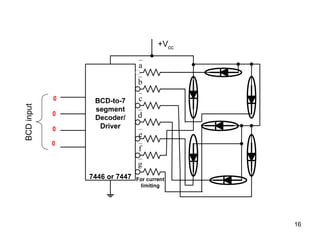
BCD-TO-7-SEGMENT DECODER/DRIVERS
‰ Most digital equipment has some means for displaying
information in a form that can be understood readily by the
user or operator.
‰ This information is often numerical data, but can also be
alphanumeric (numbers and letters).
‰ One of the simplest and most popular methods for
displaying numerical digits uses a 7-segnent configuration
[Figure 8.5(a)] to form the decimal characters 0 through 9
and sometimes the hex characters A through F.
12. 12
7446/47 Seven
7446/47 Seven-
-Segment decoder/drivers
Segment decoder/drivers
a
b
c
d
e
f
g
‰ The 7446/47 decoder/drivers are
designed to activate specific
segments even for non-BCD input
codes (greater than 1001).
‰ Figure 8.6(b) shows the activated
segment patterns for all possible
input codes from 0000 to1111.
‰ Note that an input code of 1111 (15)
will blank out all the segments.
‰ Seven-segment decoder/drivers
such as the 7446/47 are exceptions
to the rule that decoder circuits
activate only one output for each
combination of inputs.
13. 13
Logic diagram to activate segment b
‰ The function table for the BCD-to-
Seven segment decoder shown in
Figure (a).
‰ The K-map used to simplify the
logic expressions for driving
segment b is shown in Figure (b)
table below and logic diagram in
Figure (c). Entries 10-15 are
“don’t cares” as usual.
BCD Seven segment code
D C B A a b c d e f g
0 0 0 0 0 1 1 1 1 1 1 0
1 0 0 0 1 0 1 1 0 0 0 0
2 0 0 1 0 1 1 0 1 1 0 1
3 0 0 1 1 1 1 1 1 0 0 1
4 0 1 0 0 0 1 1 0 0 1 1
5 0 1 0 1 1 0 1 1 0 1 1
6 0 1 1 0 0 0 1 1 1 1 1
7 0 1 1 1 1 1 1 0 0 0 0
8 1 0 0 0 1 1 1 1 1 1 1
9 1 0 0 1 1 1 1 0 0 1 1
Decimal
digit
1
1
X
1
A
B A
B BA A
B
1
0
X
1
C
D 1
1
X
X
1
0
X
X
C
D
DC
C
D
(b)
(b)
∑
=
+
+
+
+
+
+
+
=
,7.8.9)
(0,1,2,3,4
m
A
B
C
D
A
B
C
D
CBA
D
A
B
C
D
BA
C
D
A
B
C
D
A
B
C
D
A
B
C
D
b
(a)
(a)
(c)
(c)
C
+
)
B
⊕
A
(
=
C
+
AB
+
B
A
=
b
B
A ⊕
C
)
B
A
(
Y +
⊕
=
20. 20
Encoder
‰ Most decoders accept an input code and produce a HIGH (or LOW) at
one and only one output line.
‰ In other words, we can say that a decoder identifies, recognizes, or
detects a particular code.
‰ The opposite of this decoding process is called encoding and is
performed by a logic circuit called an encoder.
‰ An encoder has a number of input lines, only one of which is activated at
a given time, and produces an N-bit output code, depending on which
input is activated.
‰ Figure 8.15 is the general diagram for and encoder with M inputs and N
outputs. Here the inputs are active- HIGH, which means they are normally
LOW
25. 25
Effect of activating two or more inputs
simultaneously
0
O
1
O
2
O
0
A
1
A
2
A
4
A
5
A
6
A
7
A
3
A
5
A
3
A
26. 26
Truth table for 8
Truth table for 8-
-line
line-
-to
to-
-3
3-
-line
line
Encoder
Encoder
Inputs Outputs
O2 O1 O0
X
X 1 1 1 1 1 1 1 0 0 0
X
X 0 1 1 1 1 1 1 0 0 1
X
X 1 0 1 1 1 1 1 0 1 0
X
X 1 1 0 1 1 1 1 0 1 1
X
X 1 1 1 0 1 1 1 1 0 0
X
X 1 1 1 1 0 1 1 1 0 1
X
X 1 1 1 1 1 0 1 1 1 0
X
X 1 1 1 1 1 1 0 1 1 1
0
A 1
A 2
A 3
A 4
A 5
A 6
A 7
A
27. 27
Effect of activating two or more simultaneously
0
O
1
O
2
O
0
A
1
A
2
A
4
A
6
A
7
A
5
A
3
A
29. 29
Verification of Priority Encoder
1
A 2
A 3
A 4
A 5
A 6
A 7
A 8
A 9
A 3
O 2
O 1
O 0
O
Inputs Outputs
1 1 1 1 1 1 1 1 1 1 1 1 1
X X X X X X X X 0 0 1 1 0
X X X X X X X 0 1 0 1 1 1
X X X X X X 0 1 1 1 0 0 0
X X X X X 0 1 1 1 1 0 0 1
X X X X 0 1 1 1 1 1 0 1 0
X X X 0 1 1 1 1 1 1 0 1 1
X X 0 1 1 1 1 1 1 1 1 0 0
X 0 1 1 1 1 1 1 1 1 1 0 1
0 1 1 1 1 1 1 1 1 1 1 1 0
30. 30
Verification of Priority Encoder
1
A 2
A 3
A 4
A 5
A 6
A 7
A 8
A 9
A 3
O 2
O 1
O 0
O
Inputs Outputs
1 1 1 1 1 1 1 1 1 1 1 1 1
X X X X X X X X 0 0 1 1 0
X X X X X X X 0 1 0 1 1 1
X X X X X X 0 1 1 1 0 0 0
X X X X X 0 1 1 1 1 0 0 1
X X X X 0 1 1 1 1 1 0 1 0
X X X 0 1 1 1 1 1 1 0 1 1
X X 0 1 1 1 1 1 1 1 1 0 0
X 0 1 1 1 1 1 1 1 1 1 0 1
0 1 1 1 1 1 1 1 1 1 1 1 0
32. 32
MULTIPLEXERS (DATA SELECTORS)
‰ A modern home stereo system may have a switch that selects
music from one of four sources:
9a cassette tape,
9a compact disc (CD),
9a turntable, or
9a radio.
‰ The switch selects one of the electronic signals from one of these
four sources and sends it to the power amplifier and speakers.
‰ In simple terms, this is what a multiplexer does; it selects one of
several input signals and passes it onto the output.
‰ A digital multiplexer
digital multiplexer or data selector
data selector is logic circuit that
accepts several digital data inputs and selects one of them at any
given time to pass on to the output.
‰ The routing of the desired data input to the output is controlled by
SELECT inputs (often referred to as ADDRESS inputs).
33. 33
Multiplexers (Data Selectors)
9 Figure above shows the functional diagram of a general digital multiplexer (MUX).
9 The multiplexer acts like a digitally controlled multi-position switch where the digital
code applied to the SELECT inputs controls which data inputs will be switched to the
output.
9 For example, output Z will equal data input I0 for some particular SELECT input code;
9 Z will equal I1 for another particular SELECT input code; and so on.
9 Stated another way, a multiplexer selects 1 out of N input data sources and transmits
the selected data to a single output channel.
9 This is called multiplexing.
34. 34
Basic Two
Basic Two-
-Input Multiplexer
Input Multiplexer
9 An example of where a two- input MUX could be used is in a
computer system that uses two different MASTER CLOCK signals:
9 a high-speed clock( say 10 MHz ) for some programs, and
9 a slow-speed clock (say 4.77 MHz) for others.
9 Using the circuit of figure above, the 10-MHz clock would be tied to
I0 and the 4.77 MHz clock to I1.
9 A signal from the computer's control logic section would drive the
SELECT input to control which clock signal appears at output Z for
routing to the other computer circuits.
0
I
Z =
1
I
Z =
S Output
0
1
S
I
S
I
Z 1
0 ⋅
+
⋅
=
35. 35
Four
Four-
-Input Multiplexer
Input Multiplexer
9 Here there are four inputs, which are selectively transmitted to the output
according to the four possible combinations of the S1S0 select inputs.
9 Each data input is gated with a different combination of select input levels.
9 I0 is gated with S1S0 so that I0 will pass through its AND gate to output Z only
when S1 = 0 and S0 = 0.
9 The table in the figure gives the outputs for the other three input select
codes.
0
I
Z =
1
I
Z =
2
I
Z =
3
I
Z =
S1 S0 Output
0 0
0 1
1 0
1 1
36. 36
Eight
Eight-
- Input Multiplexer
Input Multiplexer
‰ This multiplexer has an enable input,
E, and provides both the normal and
inverted outputs.
‰ When E =0, the select inputs S2S1S0
will select one data input (from I0
through I7) for passage to output Z.
‰ when E=1, the multiplexer is
disabled so that Z= 0 regardless of
the select input code.
‰ This operation is summarized in
figure (b), and the 74151 logic
symbol is shown in figure (c).
Z Z
E
(b)
(c)
37. 37
Example on Application of Multiplexer
Parallel-to-Serial Conversion
‰ One method for performing this parallel-to-serial
conversion uses a multiplexer, as illustrated in Figure (a).
‰ The data are present in parallel form at the outputs of the
X register and are to the eight-input multiplexer.
‰ A 3-bit (MOD-8) counter is used to provide the select code
bits S2S1S0 so that they cycle through from 000 to 111 as
clock pulses are applied.
‰ In this way, the output of the multiplexer will be X0
during the first clock period, X1 during the second clock
period, and so on.
‰ The output Z is a waveform which is a serial
representation of the parallel input data.
‰ The waveforms in the figure (b) are for the case where
X7X6X5X4X3X2X1X0 = 10110101.
‰ This conversion process takes a total of eight clock
cycles. Note that X0 (the LSB) is transmitted first and the
X7(MSB) is transmitted last. Figure (a) parallel-to-serial converter;
(b) waveforms X7X6X5X4X3X2X1X0 = 10110101
a)
a)
b)
b)
38. 38
DEMULTIPLEXERS (DATA DISTRIBUTORS)
9 A multiplexer takes several inputs and transmits one of them to the output.
9 A Demultiplexer performs the reverse operation; it takes a single input and
distributes it over several outputs.
9 Figure above shows the functional diagram for a digital Demultiplexer (DEMUX).
9 The select input code determines to which output the DATA input will be
transmitted.
9 In other words, the Demultiplexer takes one input data source and selectively
distributes it to 1 of N output channels just like a multiposition switch.
39. 39
1
1-
-Line
Line-
-to
to-
-4
4-
-Line Demultiplexer
Line Demultiplexer
‰Figure (a) shows a 1-line-to-4-line
demultiplexer circuits.
‰The input data line goes to all of the
AND gates.
‰The two select lines S0 and S1
enable only one gate at a time, and
the data appearing on the input line
will pass through the selected gate
to the associated output line.
0
1
0 S
S
I
O ⋅
⋅
=
0
1
1 S
S
I
O ⋅
⋅
=
0
1
2 S
S
I
O ⋅
⋅
=
0
1
3 S
S
I
O ⋅
⋅
=
SELECT
SELECT
Code
Code
OUTPUTS
OUTPUTS
S1 S0 O3 O2 O1 O0
0 0 0 0 0 I
0 1 0 0 I 0
1 0 0 I 0 0
1 1 I 0 0 0
(a)
40. 1
1-
-Line
Line-
-to
to-
-8
8-
-Line Demultiplexer
Line Demultiplexer
40
9 The Demultiplexer circuit of figure above is very similar to the 3-line-to-8-line decoder circuit in figure of
1-of-8 decoder except that a fourth input (I) has been added to each gate.
9 It was pointed out earlier that many IC decoders have an ENABLE input, which is an extra input added to the
decoder gates.
9 This type of decoder chip can therefore be used as a Demultiplexer, with the binary code inputs (e.g., A, B,
C in figure of 1-of-8 decoder) serving as the SELECT inputs and the ENABLE input serving as the data input I.
9 For this reason, IC manufacturers often call this type of device a decoder/Demultiplexer, and it can be used
for either function.
( )
0
1
2
0
S
S
S
I
O ⋅
=
( )
0
1
2
1
S
S
S
I
O ⋅
=
( )
0
1
2
7
S
S
S
I
O ⋅
=
( )
0
1
2
6
S
S
S
I
O ⋅
=
( )
0
1
2
5
S
S
S
I
O ⋅
=
( )
0
1
2
4
S
S
S
I
O ⋅
=
( )
0
1
2
3
S
S
S
I
O ⋅
=
( )
0
2
2
S
S
S
I
O 1
⋅
=
6
O
7
O 5
O 4
O 3
O 2
O 1
O 0
O
1
E 2
E 3
E
43. Example # 1: on Application of Demultiplexer
Example # 1: on Application of Demultiplexer
Clock Demultiplexer
‰Many applications of the demultiplexing
principle are possible.
‰Figure below shows the 74LS138
demultiplexing being used as a clock
demultiplexer.
‰Under control of the SELECT lines, the clock
signal is routed to the desired destinations.
‰For example, with S2S1S0=000, the clock signal
applied to I will appear at output .
‰With S2S1S0=110, the clock will appear at .
6
O
7
O 5
O 4
O 3
O 2
O 1
O 0
O
0
O
6
O
Figure Clock Demultiplexer transmits clock
signal to a destination determined by select
code inputs
43
44. 44
Security Monitoring System
‰Consider the case of a security monitoring system
in an industrial plant where the open/closed
status of many access doors is to be monitored.
‰Each door controls the state of a switch, and it is
necessary to display the state of each switch on
LEDs that are mounted on a remote monitoring
panel at the security guard's station.
‰One way to do this would be to run a separate
signal from each door switch to an LED on the
monitoring panel.
‰This would require running many wires over a
long distance.
‰A better approach that would reduce the amount
of wiring to the monitoring panel uses a
multiplexer/demultiplexer combination.
‰Figure shows a system that can handle eight
doors, but the basic idea can be expanded to any
number.
Z
6
O
7
O
5
O
4
O
3
O
2
O
1
O
0
O
Ω
330
45. Example #2: on Application of Demultiplexer
Example #2: on Application of Demultiplexer
45
Circuit Operation
Circuit Operation
‰ The eight door switches are the data inputs to the MUX; they produce a HIGH when a door is open and
a LOW when it is closed.
‰ The MOD-8 counter provides the select inputs to the MUX and also to the DEMUX on the remote
monitoring panel.
‰ Each DEMUX output is connected to an indicator LED that will be on when the output is LOW. Clock
pulses applied to the counter will cause the select inputs to sequence through all of the possible
states 000 through 111. At each number of the counter, the switch status for the door of the same
number will be inverted by the MUX and passed to output. From there it is transmitted to the DEMUX
input, which passes it through to the output corresponding to the same number.
‰ For example, let's say that the counter is at the count of 110 (6). While the counter is in this state,
let's say that door 6 is closed. The LOW at I6 will pass through the MUX and be inverted to produce a
HIGH at .
‰ This HIGH will be passing through the DEMUX to output so that LED 6 will be off, indicating that
door 6 is closed.
‰ Now let's say that door 6 is open. A LOW will appear at and so that LED 6 will be on to signal
that door 6 is open.
‰ Of course, all other LEDs will be off during this time since is the only active output.
Z
6
O
6
O
Z
6
O
46. Circuit operation continued
46
‰As the counter is clocked through its eight states 000 through 111, the LEDs will
sequentially indicate the status of the eight doors.
‰If all the doors are closed, none of the LEDs will be on even when the
corresponding DEMUX output is selected.
‰If a door is open, its LED will turn on only during the time interval that the
counter is at the appropriate count; it will be off at all other counts.
‰Thus, the LED will be flashing on and off if its door is open.
‰The flashing rate can be adjusted by changing the frequency of the clock.
‰Note that there are only four signal lines going from the "door sensing" circuitry
to the remote monitoring panel: the output and the three select lines.
‰This is a saving of four lines when compared with the alternative of having one
line per door.
‰The MUX/DEMUX combination is used to transmit the status of each door to its
LED one at a time (serially) instead of all at once (parallel).
Z