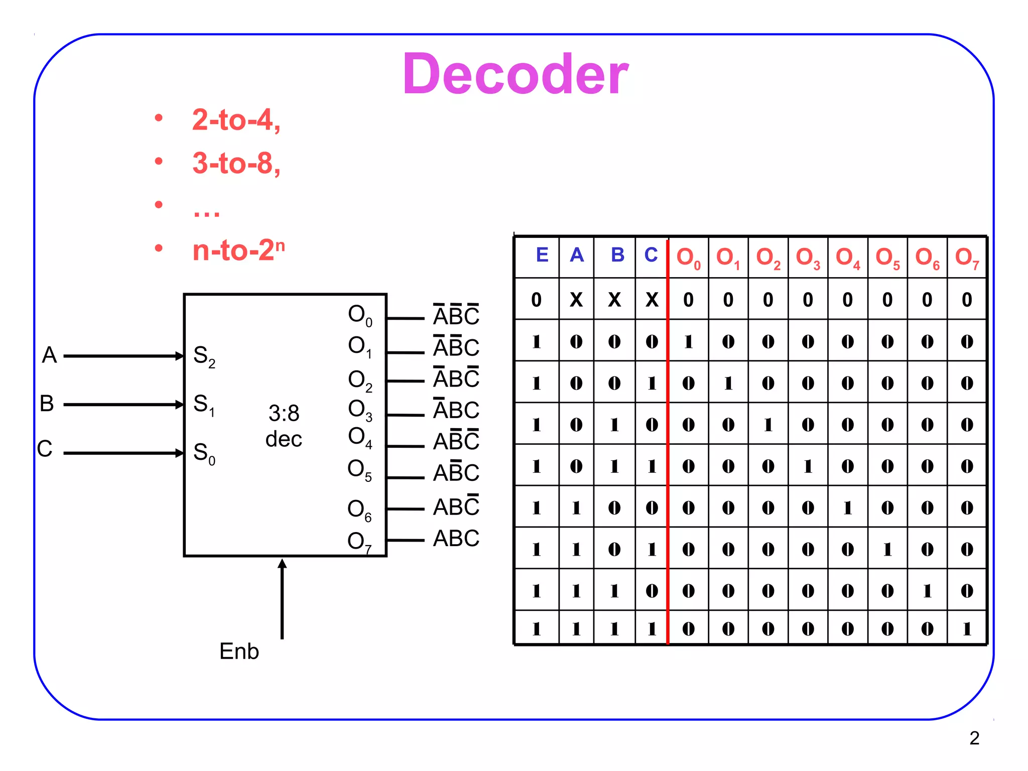
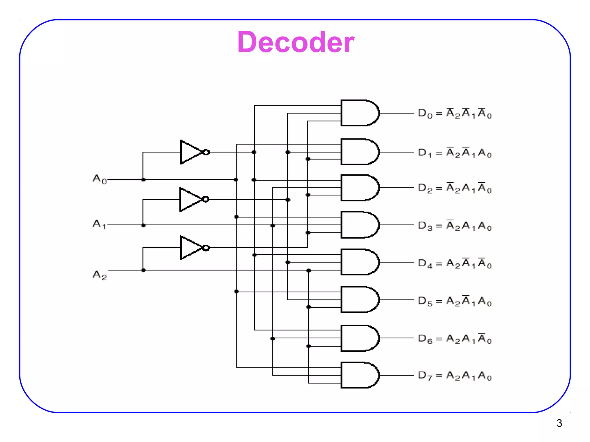
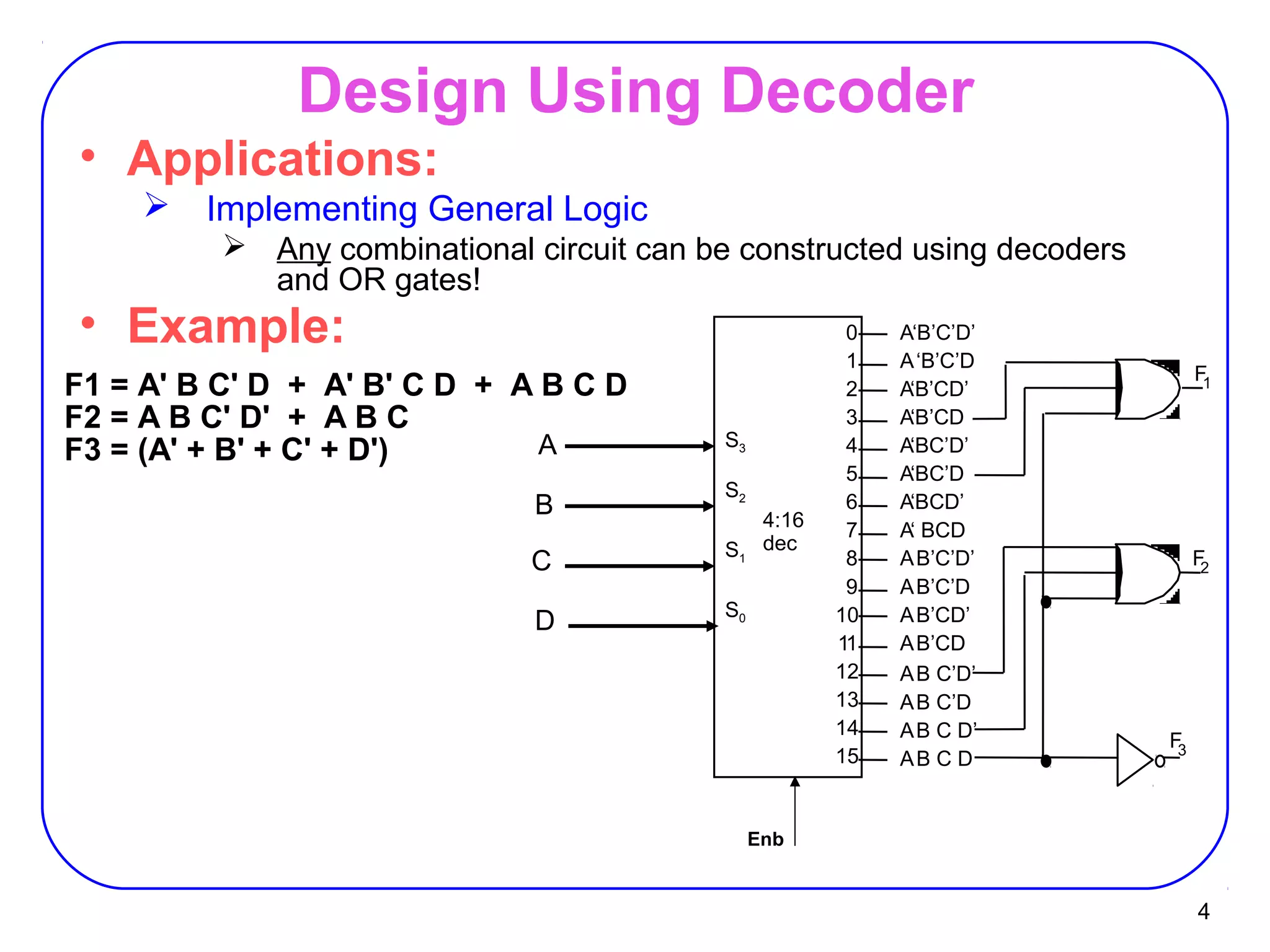
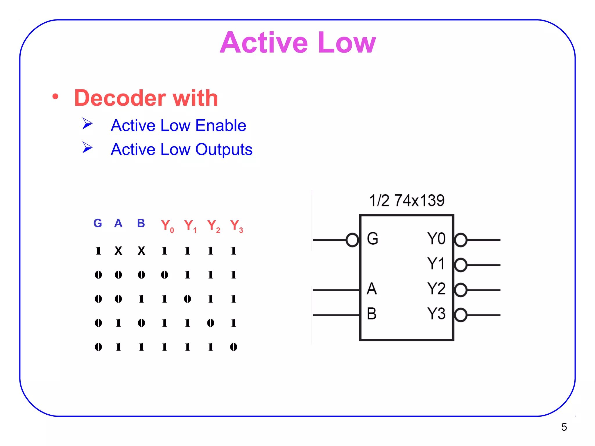
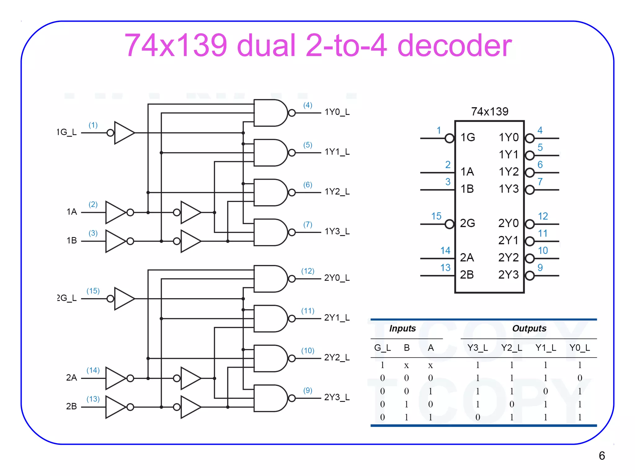
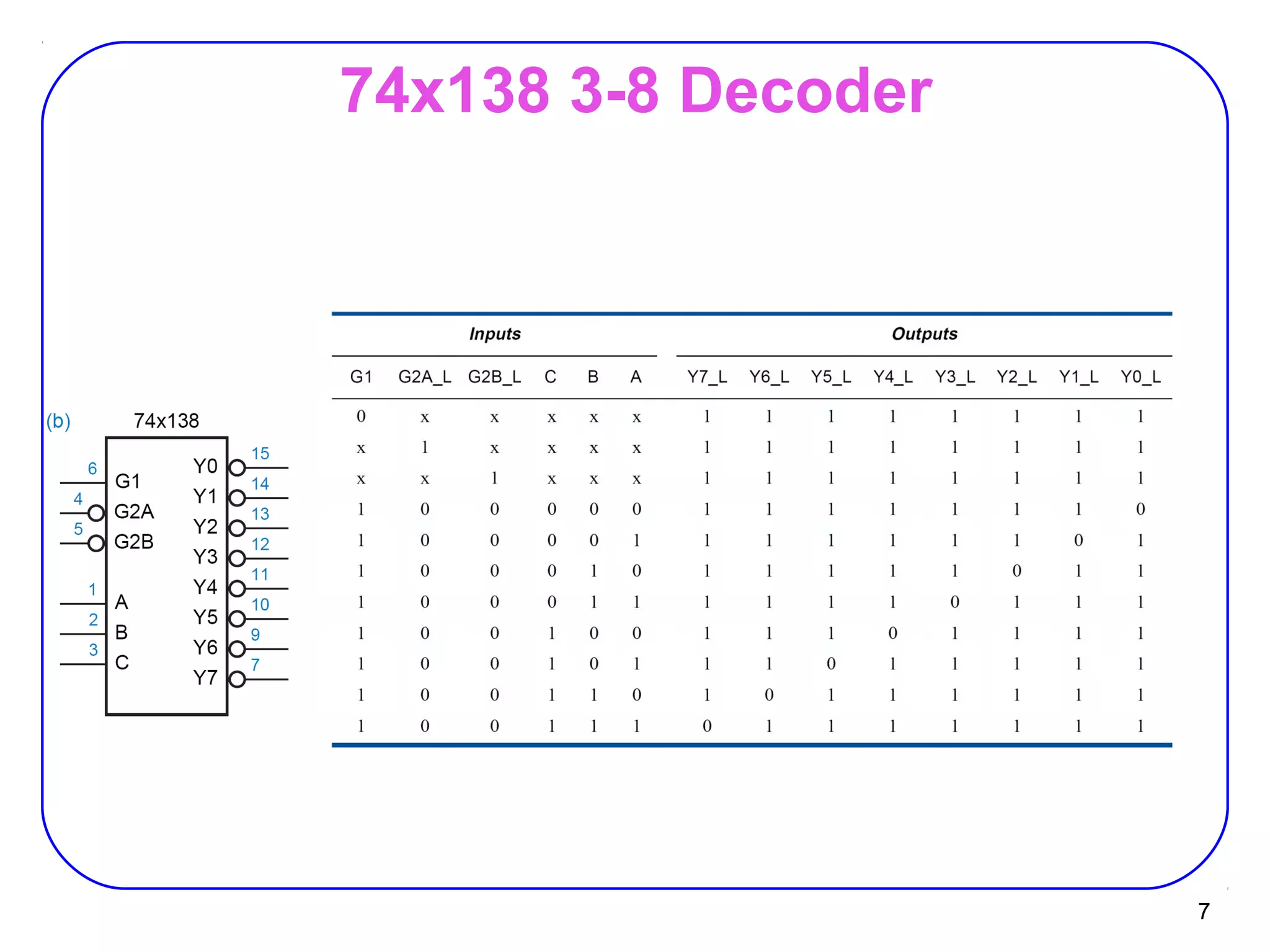
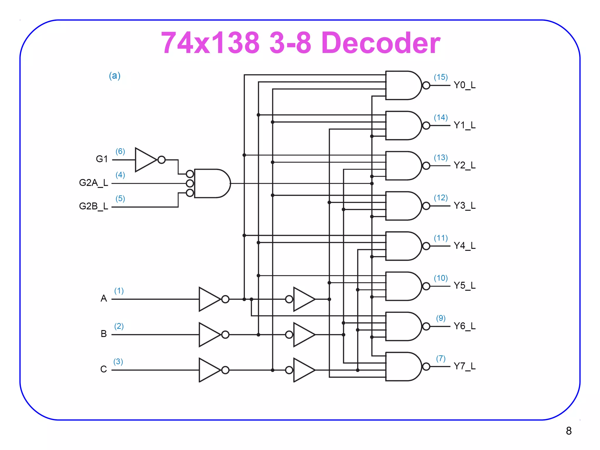
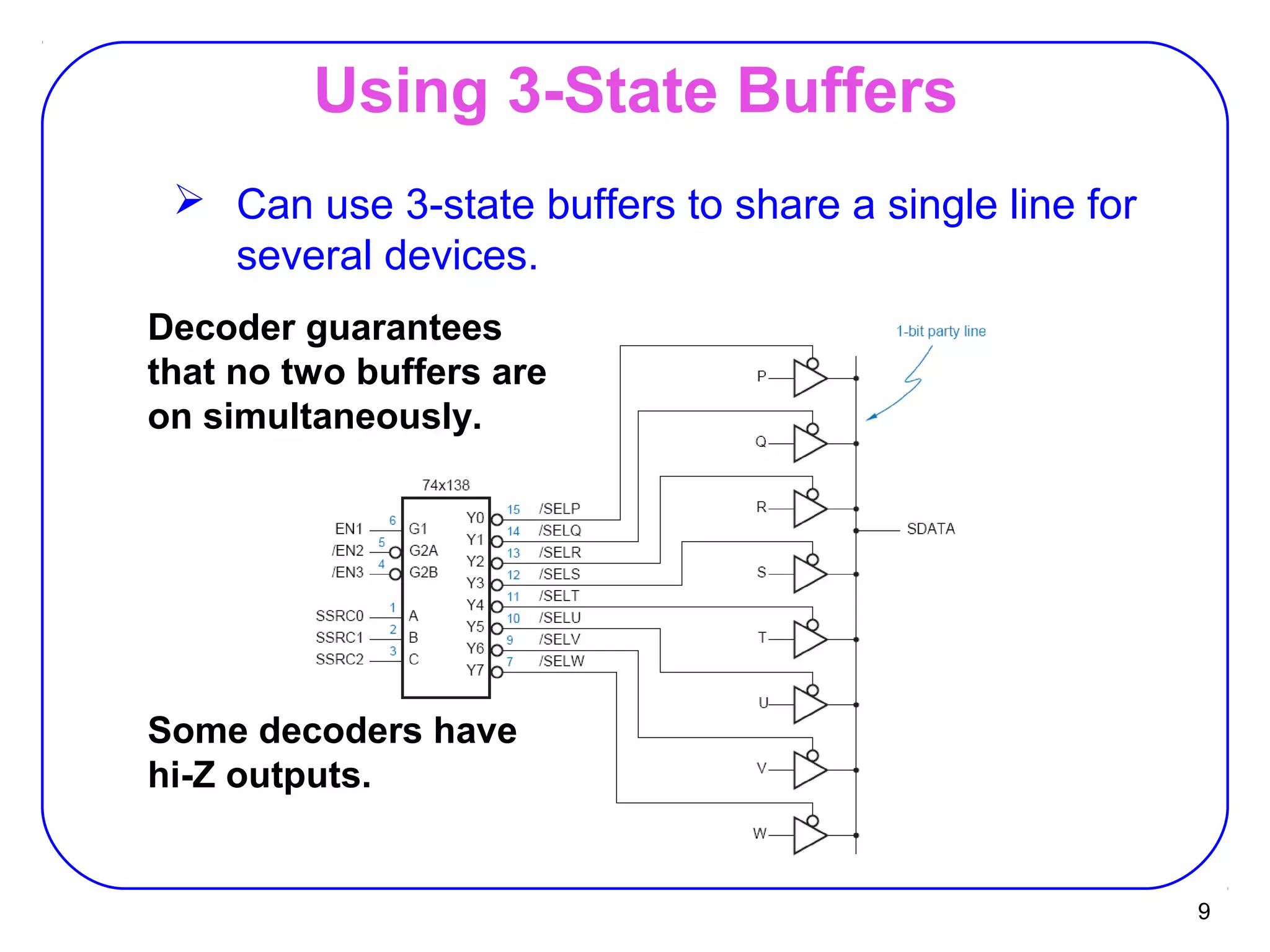
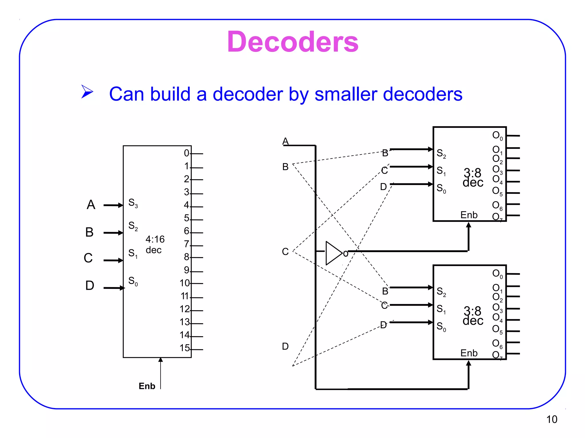
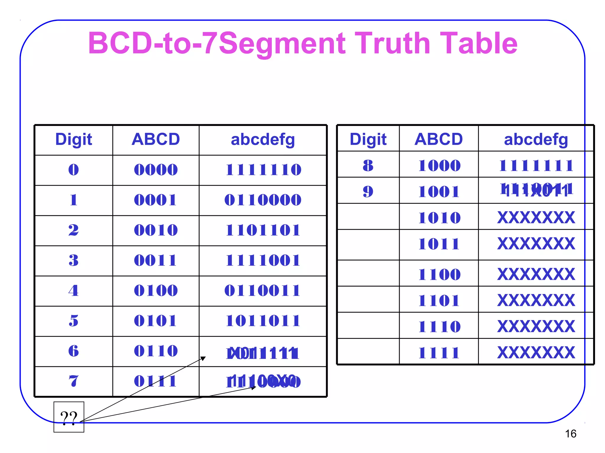
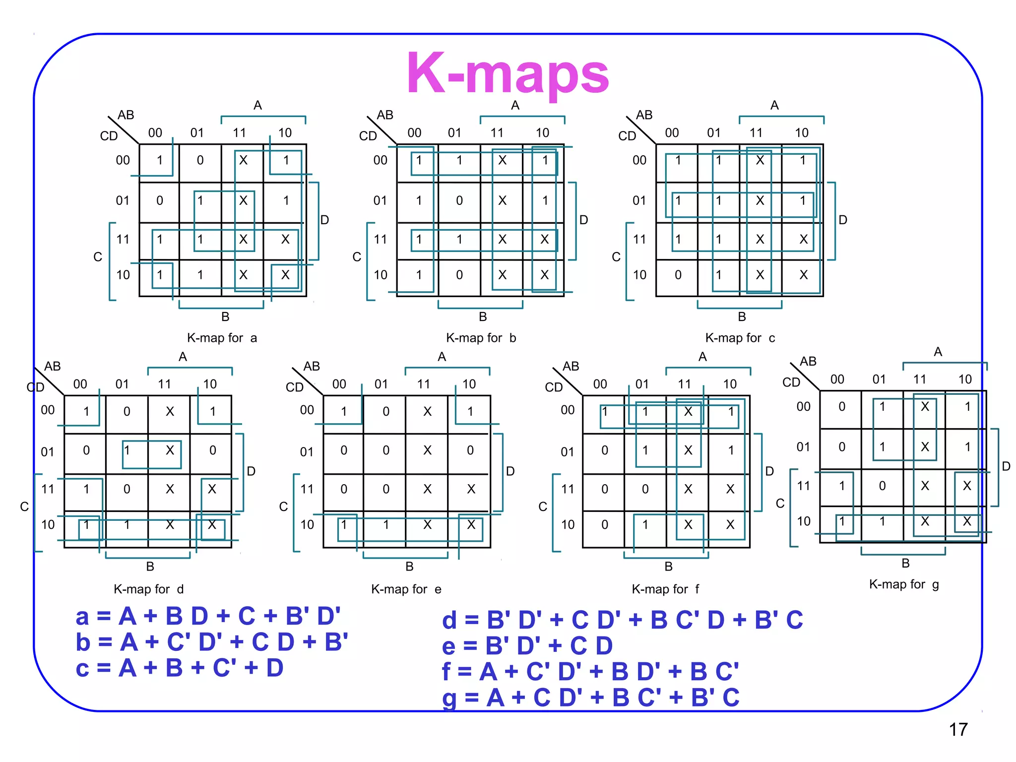
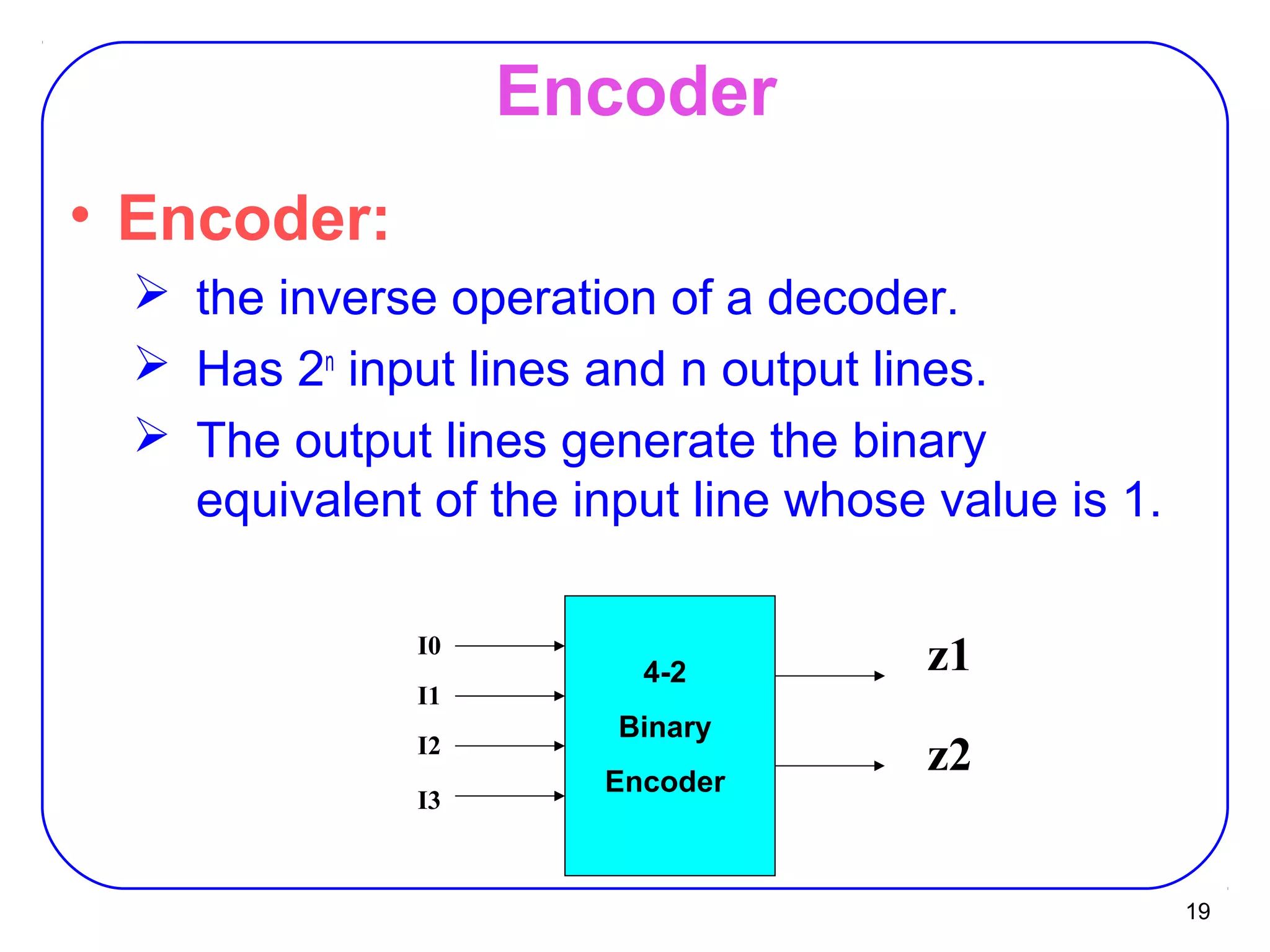
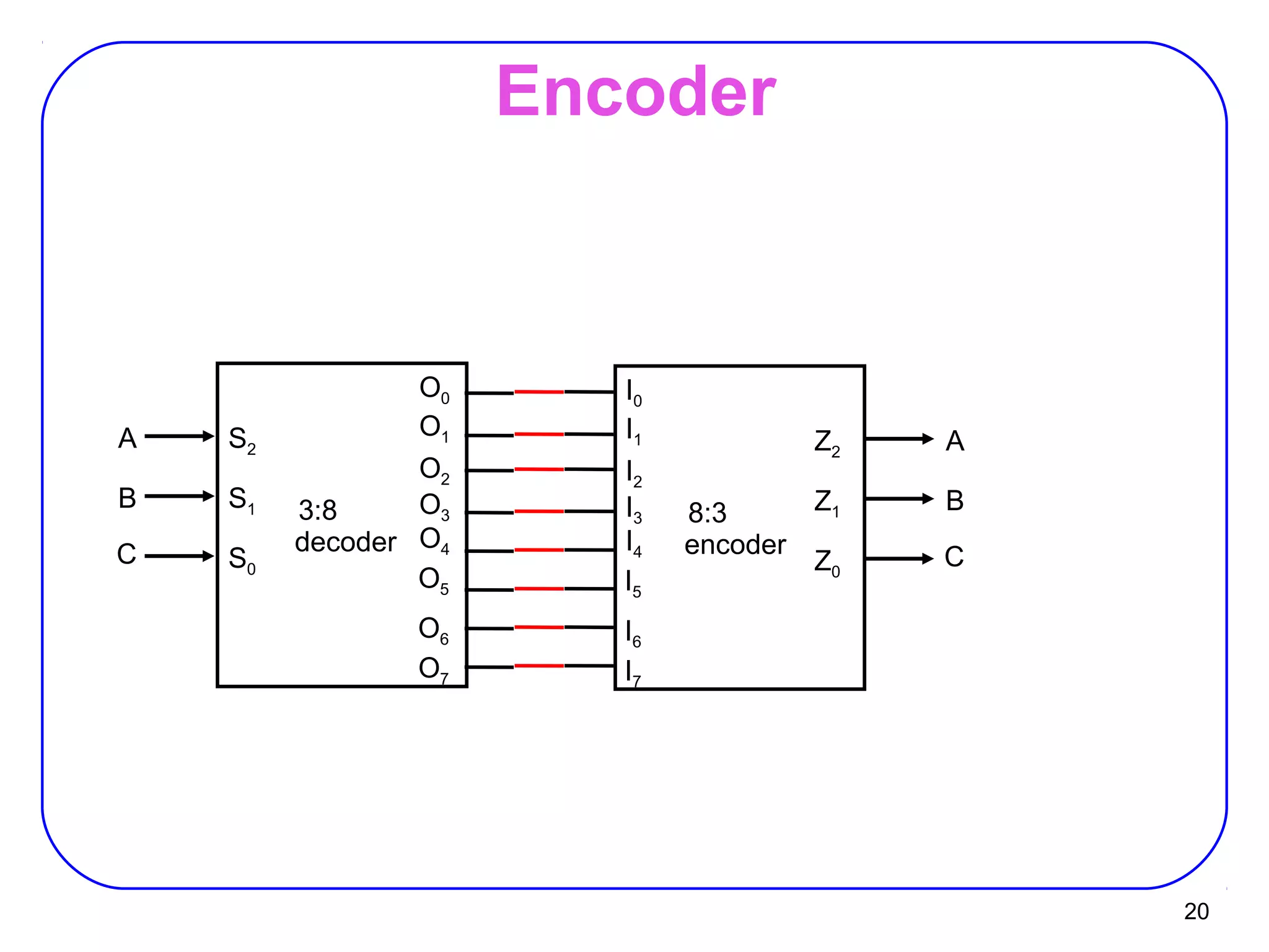
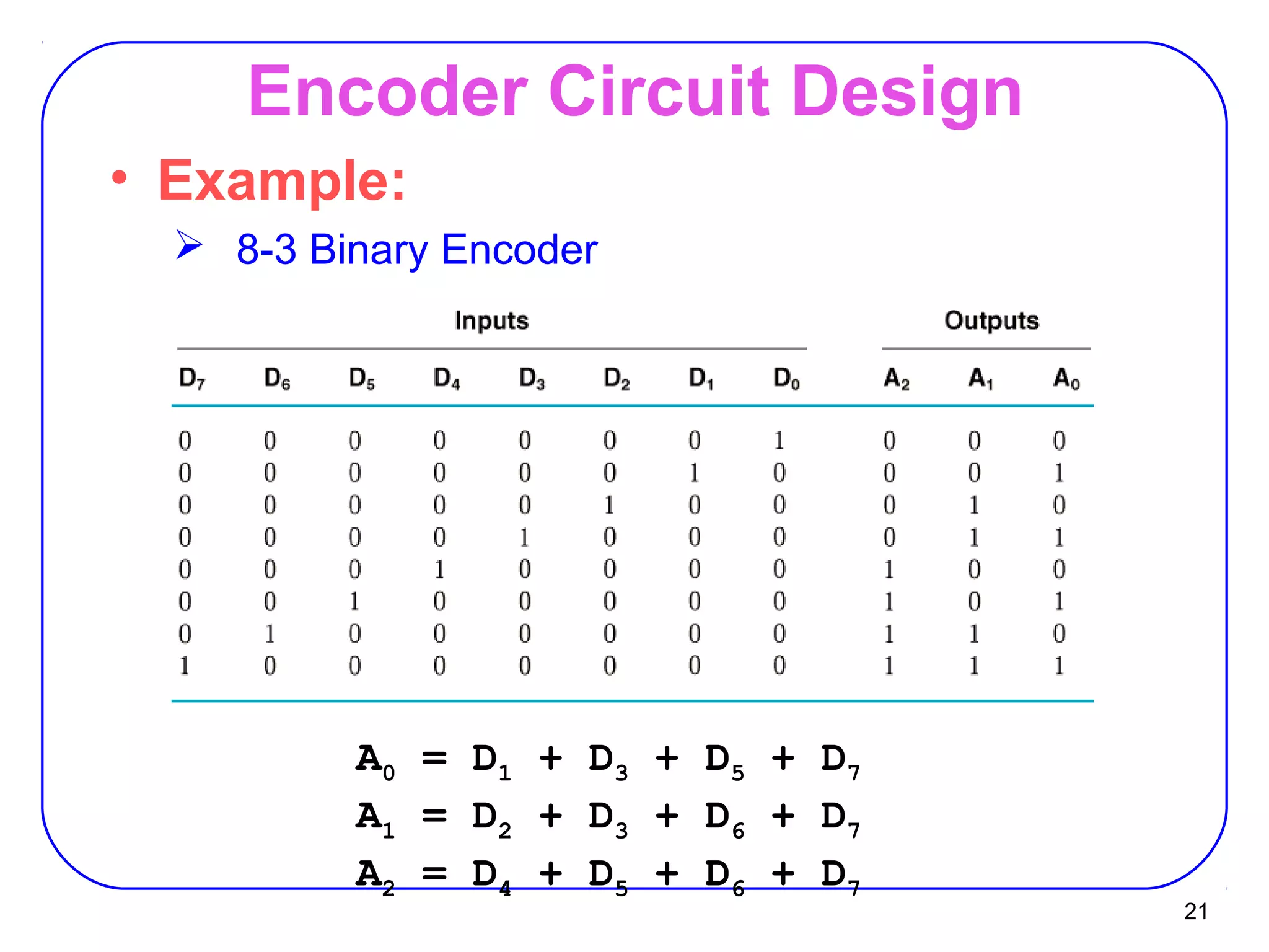
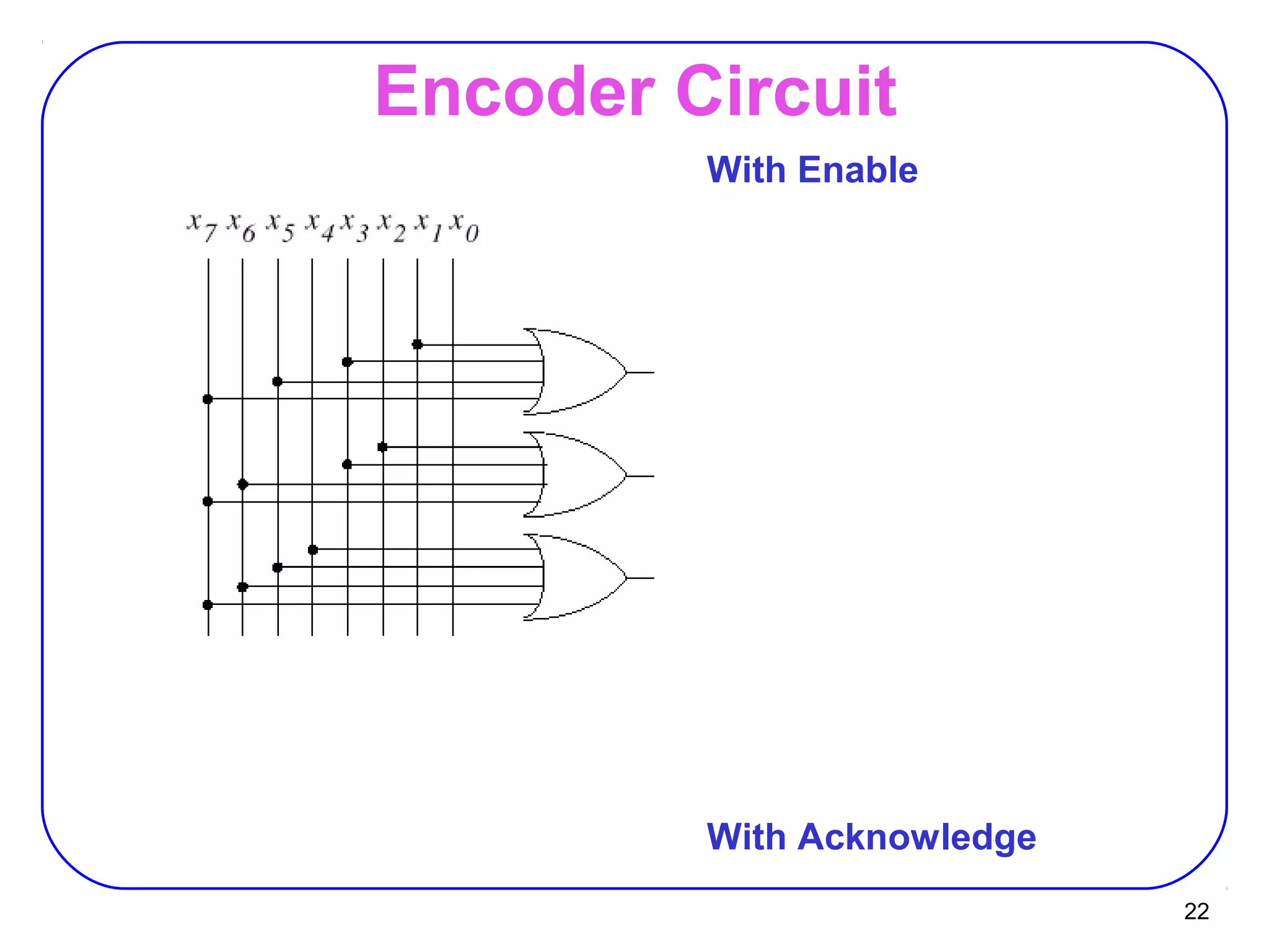
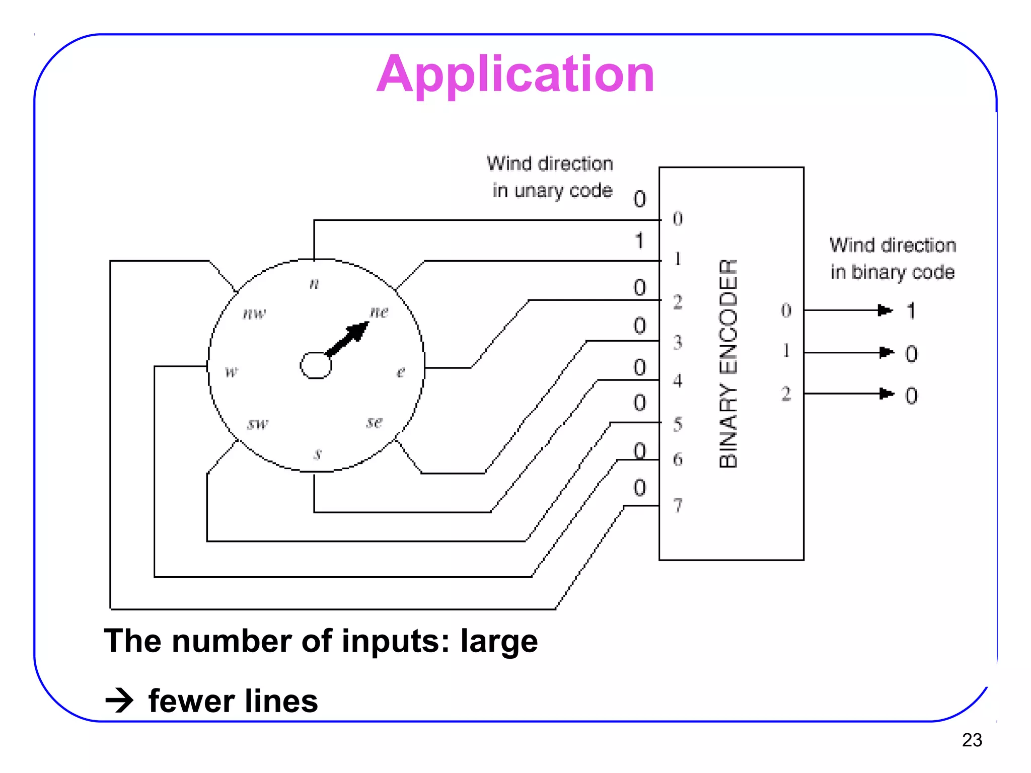
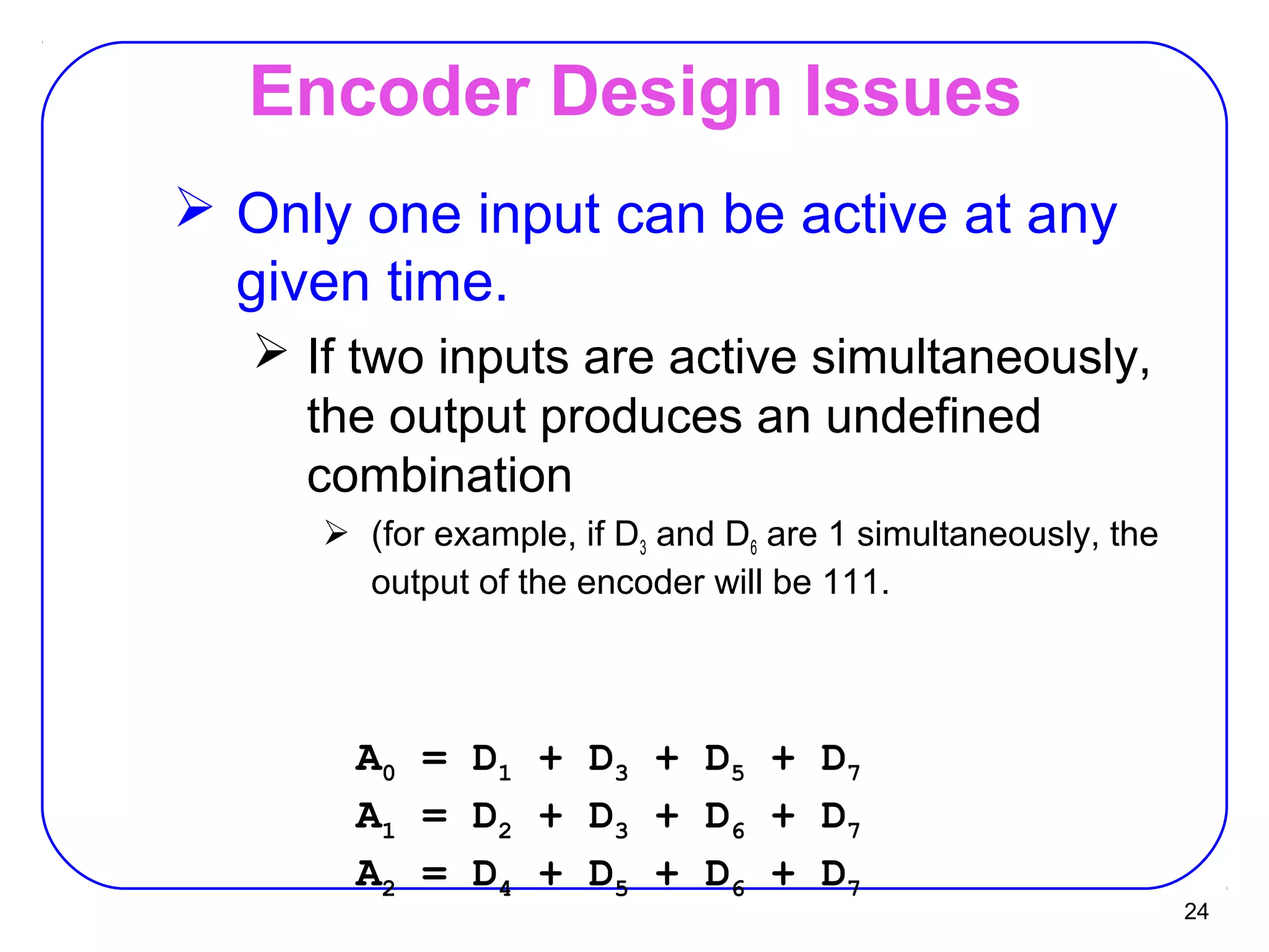
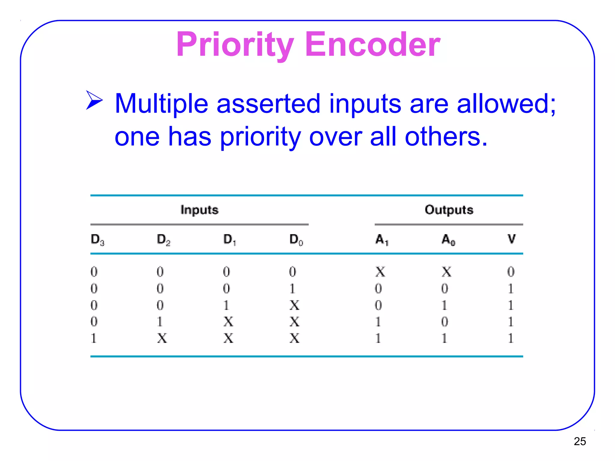
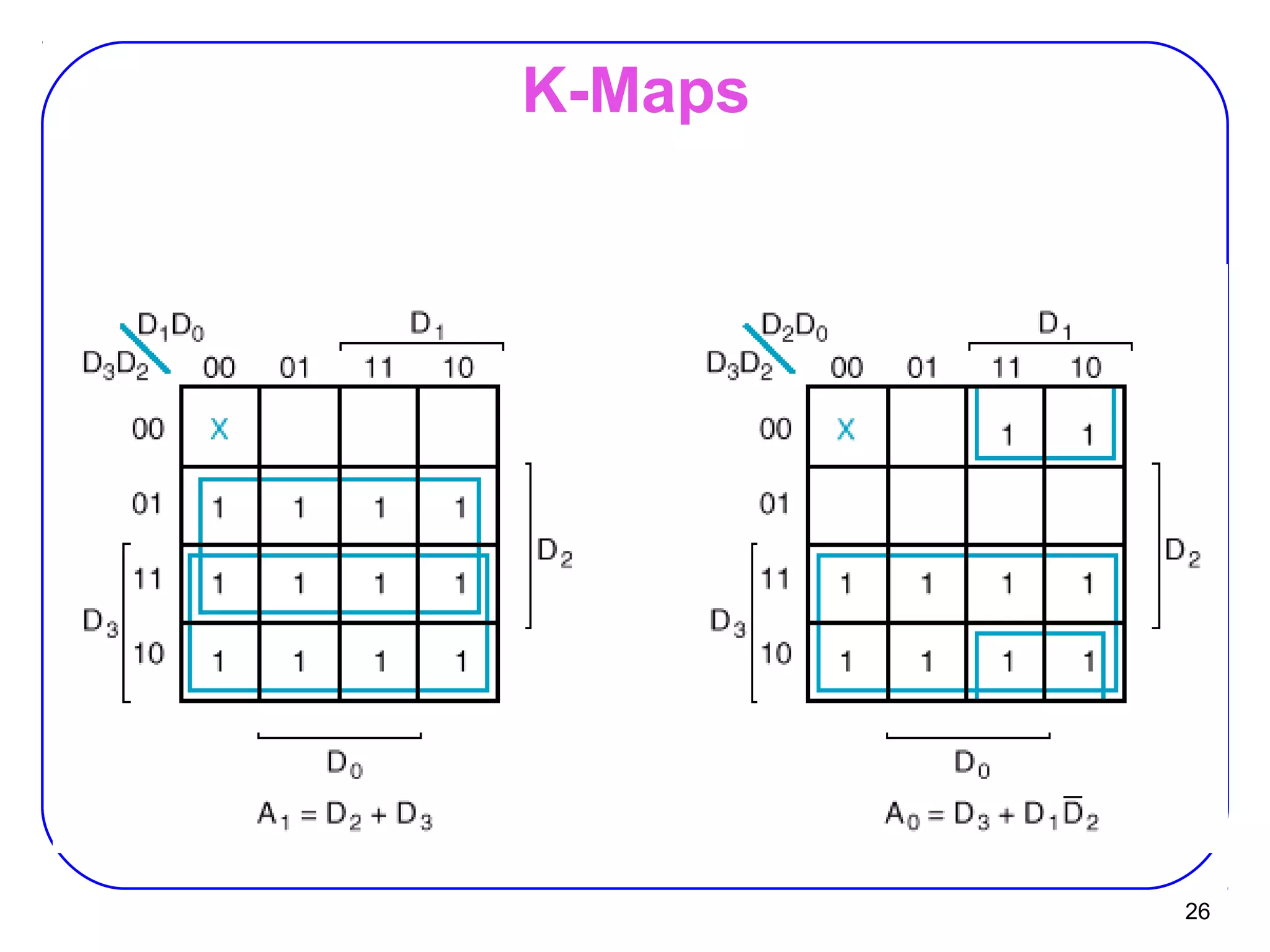
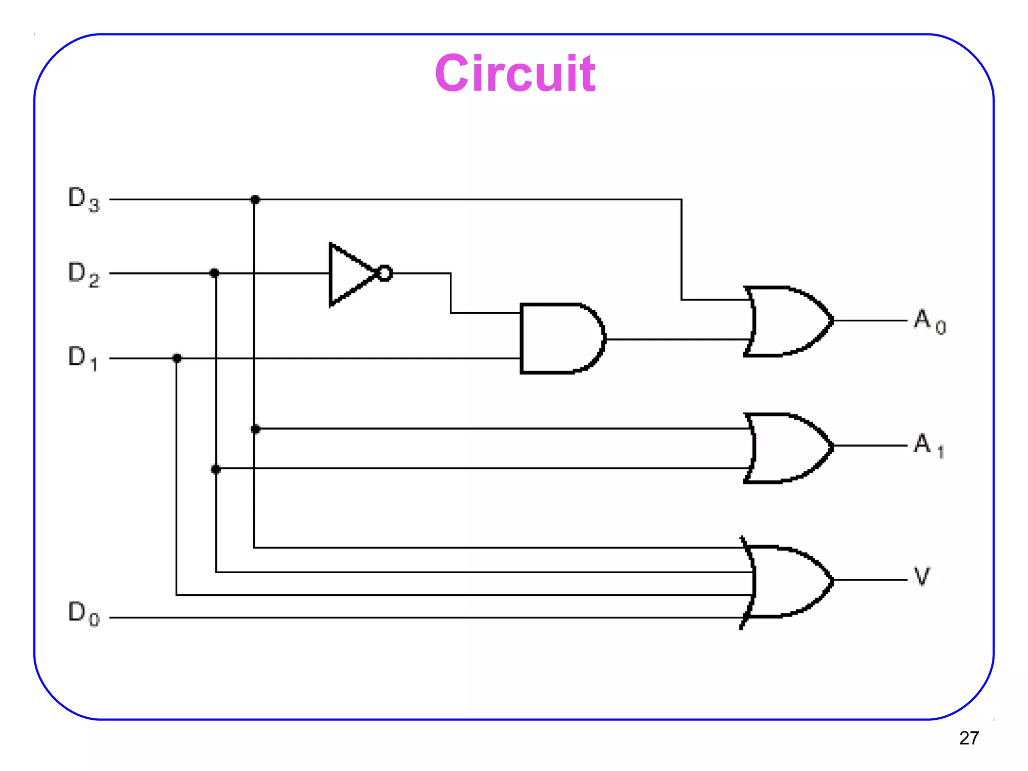
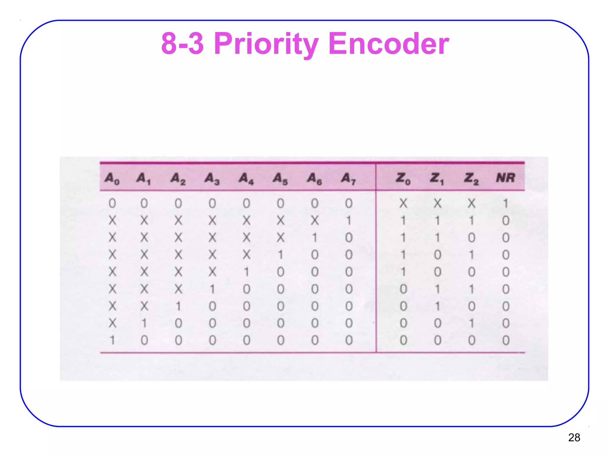
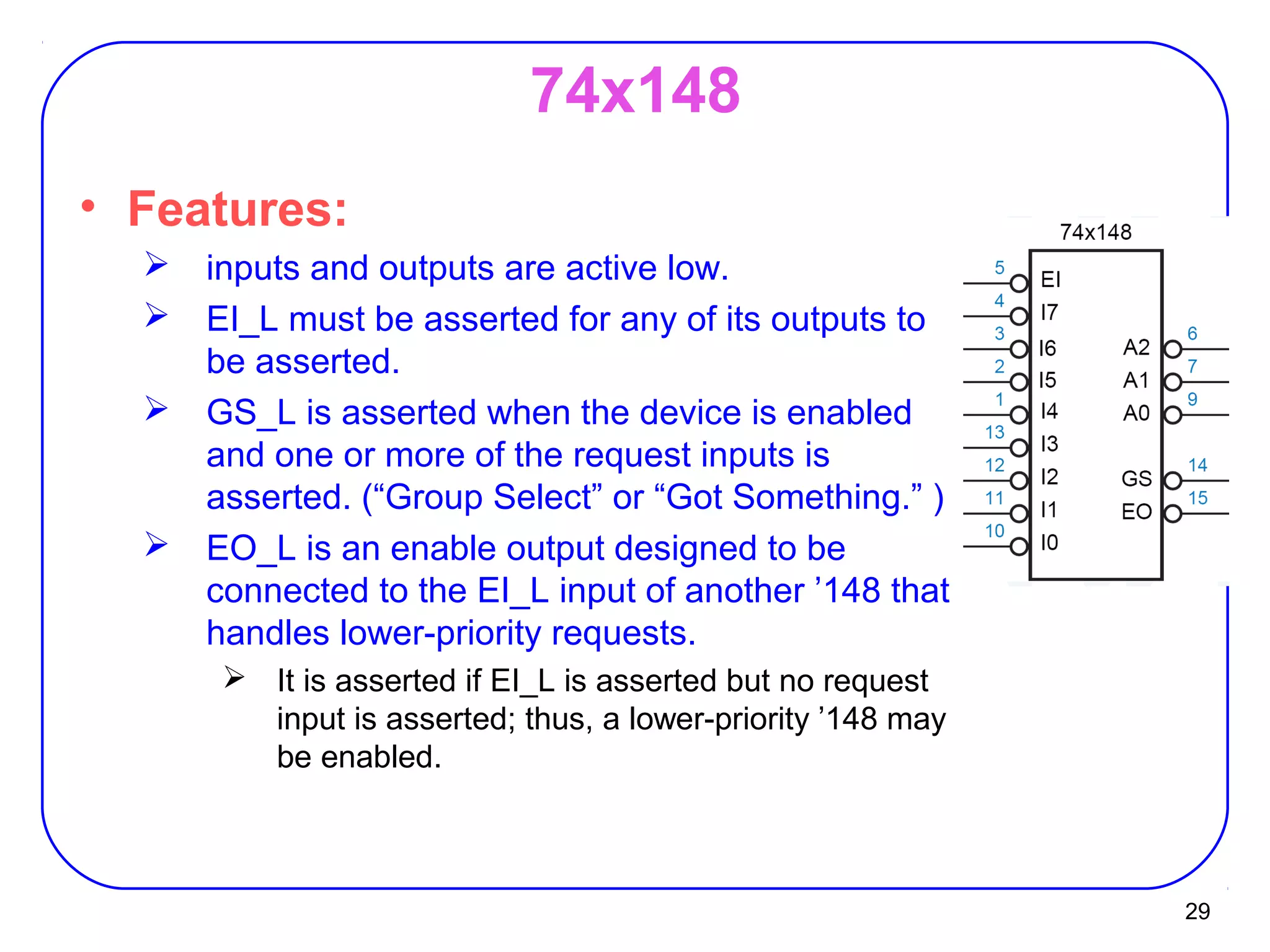
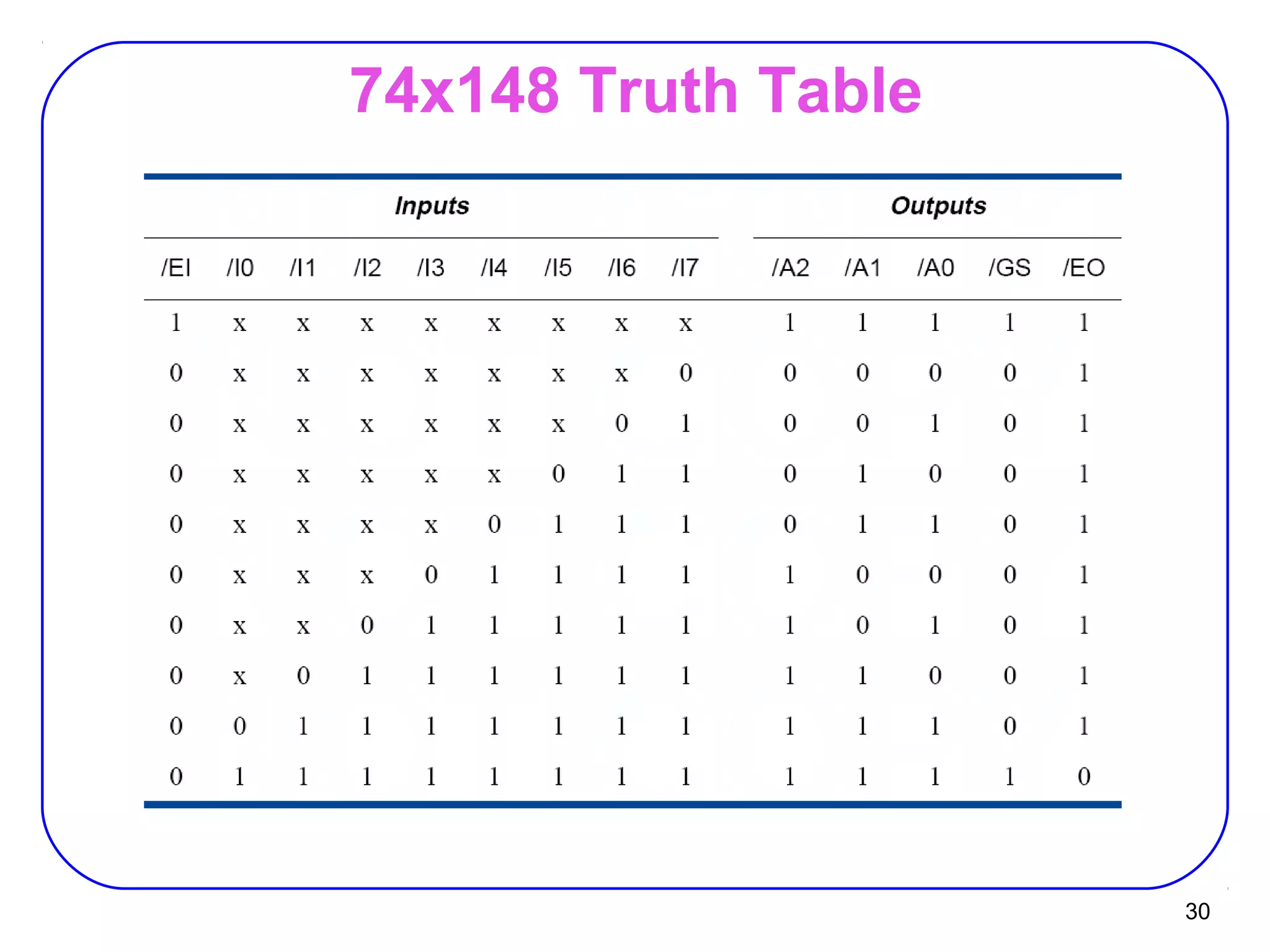
The document describes decoders and encoders. It begins by explaining what a decoder is, providing examples of 2-to-4 and 3-to-8 decoders. It then discusses how decoders can be used to implement general logic and combinational circuits using decoders and OR gates. The document proceeds to describe specific decoder chips like the 74x139 and 74x138 decoders. It also discusses using 3-state buffers with decoders and building decoders from smaller decoders. The document then shifts to discussing encoders, 7-segment decoders, truth tables, and K-maps in the design of decoders and encoders. It concludes by discussing priority encoders and the 74x148 priority encoder chip.
In which i describe all the features of decoder. All the functionalities describe with the circuits and truth tables. So download and learn more about decoder. Decoder Full Presentation.
In digital electronics, a decoder can take the form of a multiple-input, multiple-output logic circuit that converts coded inputs into coded outputs, where the input and output codes are different e.g. n-to-2n , binary-coded decimal decoders. Decoding is necessary in applications such as data multiplexing, 7 segment display and memory address decoding.
An encoder is a device, circuit, transducer, software program, algorithm or person that converts information from one format or code to another. The purpose of encoder is standardization, speed, secrecy, security, or saving space by shrinking size. Encoders are combinational logic circuits and they are exactly opposite of decoders. They accept one or more inputs and generate a multibit output code.
An adder is a digital logic circuit in electronics that implements addition of numbers. In many computers and other types of processors, adders are used to calculate addresses, similar operations and table indices in the ALU and also in other parts of the processors. These can be built for many numerical representations like excess-3 or binary coded decimal
The Reconfigurable Video Coding (RVC) framework is a recent ISO standard aiming at providing a unified specification of MPEG video technology in the form of a library of components. The word “reconfigurable” evokes run-time instantiation of different decoders starting from an on-the-fly analysis of the input bitstream.
In this paper we move a first step towards the definition of systematic procedures that, based on the MPEG RVC specification formalism, are able to produce multi-decoder platforms, capable of fast switching between different configurations. Looking at the similarities between the decoding algorithms to implement, the papers describes an automatic tool for their composition into a single configurable multi-decoder built of all the required modules, and able to reuse the shared components so as to reduce the overall footprint (either from a hardware or software perspective).
The proposed approach, implemented in C++ leveraging on Flex and Bison code generation tools, typically exploited in the compilers front-end, demonstrates to be successful in the composition of two different decoders MPEG-4 Part 2 (SP): serial and parallel.
Design of wireless power transfer system via magnetic resonant coupling at 13...Ajay Kumar Sah
Design of Wireless Power Transfer System via Magnetic Resonant Coupling at 13.56MHz
Abstract: Power is a must to modern systems. Power transmission through wires is common. But not in every field can wires be used because of certain limitations. The implantable biomedical devices like pacemakers, cardiac defibrillators, and artificial hearts require power supply for long term operation. The required power is supplied by driveline cable or by battery. WPT greatly reduces the risk of infection by eliminating the driveline cable which otherwise needs to puncture the skin to provide power and also saves the valuable space inside a person’s body in case of battery powered. In such fields, what we need is wireless transmission. Wireless transmission is useful in cases where instantaneous or continuous energy transfer is needed, but interconnecting wires are inconvenient, hazardous, or impossible. In this paper, a simple design method of a wireless power transfer system using 13.56 MHz ISM band is proposed. The proposed wireless power transfer system consists of rectifier, oscillator, power amplifier, power coil, load coil and two intermediate coils as transmitter antenna and receiver antenna inserted between power coil and load coil.
Analysis and optimization of wireless power transfer linkAjay Kumar Sah
In this presentation, a high efficiency Gallium nitride (GaN), HEMT (High Electron Mobility Transistor) class-E power amplifier for the wireless power transfer link is designed and simulated on PSpice. A four-coil wireless power transfer link is modeled for maximum power transfer efficiency on ADS (Advanced Design System) and frequency splitting phenomenon is demonstrated, explained and analyzed. Two resonant coupling structures, series & mixed, are presented and compared. The efficiency performance of the link is studied using spiral and helical antennas of different wire make. In addition, techniques for improving efficiency of the wireless power transfer systems with changing coupling coefficient viz. frequency splitting phenomenon of the coils are proposed.
Welcome to WIPAC Monthly the magazine brought to you by the LinkedIn Group Water Industry Process Automation & Control.
In this month's edition, along with this month's industry news to celebrate the 13 years since the group was created we have articles including
A case study of the used of Advanced Process Control at the Wastewater Treatment works at Lleida in Spain
A look back on an article on smart wastewater networks in order to see how the industry has measured up in the interim around the adoption of Digital Transformation in the Water Industry.
Courier management system project report.pdfKamal Acharya
It is now-a-days very important for the people to send or receive articles like imported furniture, electronic items, gifts, business goods and the like. People depend vastly on different transport systems which mostly use the manual way of receiving and delivering the articles. There is no way to track the articles till they are received and there is no way to let the customer know what happened in transit, once he booked some articles. In such a situation, we need a system which completely computerizes the cargo activities including time to time tracking of the articles sent. This need is fulfilled by Courier Management System software which is online software for the cargo management people that enables them to receive the goods from a source and send them to a required destination and track their status from time to time.
COLLEGE BUS MANAGEMENT SYSTEM PROJECT REPORT.pdfKamal Acharya
The College Bus Management system is completely developed by Visual Basic .NET Version. The application is connect with most secured database language MS SQL Server. The application is develop by using best combination of front-end and back-end languages. The application is totally design like flat user interface. This flat user interface is more attractive user interface in 2017. The application is gives more important to the system functionality. The application is to manage the student’s details, driver’s details, bus details, bus route details, bus fees details and more. The application has only one unit for admin. The admin can manage the entire application. The admin can login into the application by using username and password of the admin. The application is develop for big and small colleges. It is more user friendly for non-computer person. Even they can easily learn how to manage the application within hours. The application is more secure by the admin. The system will give an effective output for the VB.Net and SQL Server given as input to the system. The compiled java program given as input to the system, after scanning the program will generate different reports. The application generates the report for users. The admin can view and download the report of the data. The application deliver the excel format reports. Because, excel formatted reports is very easy to understand the income and expense of the college bus. This application is mainly develop for windows operating system users. In 2017, 73% of people enterprises are using windows operating system. So the application will easily install for all the windows operating system users. The application-developed size is very low. The application consumes very low space in disk. Therefore, the user can allocate very minimum local disk space for this application.
Quality defects in TMT Bars, Possible causes and Potential Solutions.PrashantGoswami42
Maintaining high-quality standards in the production of TMT bars is crucial for ensuring structural integrity in construction. Addressing common defects through careful monitoring, standardized processes, and advanced technology can significantly improve the quality of TMT bars. Continuous training and adherence to quality control measures will also play a pivotal role in minimizing these defects.
Sachpazis:Terzaghi Bearing Capacity Estimation in simple terms with Calculati...Dr.Costas Sachpazis
Terzaghi's soil bearing capacity theory, developed by Karl Terzaghi, is a fundamental principle in geotechnical engineering used to determine the bearing capacity of shallow foundations. This theory provides a method to calculate the ultimate bearing capacity of soil, which is the maximum load per unit area that the soil can support without undergoing shear failure. The Calculation HTML Code included.
Democratizing Fuzzing at Scale by Abhishek Aryaabh.arya
Presented at NUS: Fuzzing and Software Security Summer School 2024
This keynote talks about the democratization of fuzzing at scale, highlighting the collaboration between open source communities, academia, and industry to advance the field of fuzzing. It delves into the history of fuzzing, the development of scalable fuzzing platforms, and the empowerment of community-driven research. The talk will further discuss recent advancements leveraging AI/ML and offer insights into the future evolution of the fuzzing landscape.
CFD Simulation of By-pass Flow in a HRSG module by R&R Consult.pptxR&R Consult
CFD analysis is incredibly effective at solving mysteries and improving the performance of complex systems!
Here's a great example: At a large natural gas-fired power plant, where they use waste heat to generate steam and energy, they were puzzled that their boiler wasn't producing as much steam as expected.
R&R and Tetra Engineering Group Inc. were asked to solve the issue with reduced steam production.
An inspection had shown that a significant amount of hot flue gas was bypassing the boiler tubes, where the heat was supposed to be transferred.
R&R Consult conducted a CFD analysis, which revealed that 6.3% of the flue gas was bypassing the boiler tubes without transferring heat. The analysis also showed that the flue gas was instead being directed along the sides of the boiler and between the modules that were supposed to capture the heat. This was the cause of the reduced performance.
Based on our results, Tetra Engineering installed covering plates to reduce the bypass flow. This improved the boiler's performance and increased electricity production.
It is always satisfying when we can help solve complex challenges like this. Do your systems also need a check-up or optimization? Give us a call!
Work done in cooperation with James Malloy and David Moelling from Tetra Engineering.
More examples of our work https://www.r-r-consult.dk/en/cases-en/
Forklift Classes Overview by Intella PartsIntella Parts
Discover the different forklift classes and their specific applications. Learn how to choose the right forklift for your needs to ensure safety, efficiency, and compliance in your operations.
For more technical information, visit our website https://intellaparts.com
4. 4
Design Using Decoder
• Applications:
Implementing General Logic
Any combinational circuit can be constructed using decoders
and OR gates!
F1 = A' B C' D + A' B' C D + A B C D
F2 = A B C' D' + A B C
F3 = (A' + B' + C' + D')
• Example: A‘B’C’D’
A‘B’C’D
A‘B’CD’
A‘B’CD
A‘BC’D’
A‘BC’D
A‘BCD’
A‘ BCD
AB’C’D’
AB’C’D
AB’CD’
AB’CD
AB C’D’
AB C’D
AB C D’
AB C D
F1
F3
F2
A
B
C
D
S2
S1
S0
S3
0
1
2
3
4
5
6
7
8
9
10
11
12
13
14
15
4:16
dec
Enb
5. 5
Active Low
• Decoder with
Active Low Enable
Active Low Outputs
G A B Y0 Y1 Y2 Y3
1 X X 1 1 1 1
0 0 0 0 1 1 1
0 0 1 1 0 1 1
0 1 0 1 1 0 1
0 1 1 1 1 1 0
9. 9
Using 3-State Buffers
Can use 3-state buffers to share a single line for
several devices.
Decoder guarantees
that no two buffers are
on simultaneously.
Some decoders have
hi-Z outputs.
10. 10
Decoders
Can build a decoder by smaller decoders
A
B
C
D
S2
S1
S0
S3
0
1
2
3
4
5
6
7
8
9
10
11
12
13
14
15
4:16
dec
Enb
3:8
dec
O0
O1
O2
B
C
D
Enb
S2
S1
S0
O3
O4
O5
O6
O7
3:8
dec
O0
O1
O2
B
C
D
Enb
S2
S1
S0
O3
O4
O5
O6
O7
A
B
C
D
13. 13
7-Segment Decoder
• Seven-segment display:
7 LEDs (light emitting diodes), each one
controlled by an input
1 means “on”, 0 means “off”
Display digit “3”?
Set a, b, c, d, g to 1
Set e, f to 0
d
a
b
ce
f
g
15. 15
7-Segment Decoder
• 7-Segment Decoder:
Input is a 4-bit BCD code 4 inputs (A, B, C,
D).
Output is a 7-bit code (a,b,c,d,e,f,g) that
allows for the decimal equivalent to be
displayed.
• Example:
Input: 0000BCD
Output: 1111110
(a=b=c=d=e=f=1, g=0)
d
a
b
ce
f g
17. 17
K-maps
a = A + B D + C + B' D'
b = A + C' D' + C D + B'
c = A + B + C' + D
d = B' D' + C D' + B C' D + B' C
e = B' D' + C D
f = A + C' D' + B D' + B C'
g = A + C D' + B C' + B' C
AB
CD 00 01 11 10
00
01
11
10
D
B
C
A
1 0 X 1
0 1 X 1
1 1 X X
1 1 X X
K-map for a
AB
CD 00 01 11 10
00
01
11
10
D
B
C
A
1 1 X 1
1 0 X 1
1 1 X X
1 0 X X
K-map for b
AB
CD 00 01 11 10
00
01
11
10
D
B
C
A
1 1 X 1
1 1 X 1
1 1 X X
0 1 X X
K-map for c
AB
CD 00 01 11 10
00
01
11
10
D
B
C
A
1 0 X 1
0 1 X 0
1 0 X X
1 1 X X
K-map for d
AB
CD 00 01 11 10
00
01
11
10
D
B
C
A
1 0 X 1
0 0 X 0
0 0 X X
1 1 X X
K-map for e
AB
CD 00 01 11 10
00
01
11
10
D
B
C
A
1 1 X 1
0 1 X 1
0 0 X X
0 1 X X
K-map for f
AB
CD 00 01 11 10
00
01
11
10
D
B
C
A
0 1 X 1
0 1 X 1
1 0 X X
1 1 X X
K-map for g
19. 19
Encoder
• Encoder:
the inverse operation of a decoder.
Has 2n
input lines and n output lines.
The output lines generate the binary
equivalent of the input line whose value is 1.
I0
I1
I2
I3
z1
z2
4-2
Binary
Encoder
24. 24
Encoder Design Issues
Only one input can be active at any
given time.
If two inputs are active simultaneously,
the output produces an undefined
combination
(for example, if D3 and D6 are 1 simultaneously, the
output of the encoder will be 111.
A0 = D1 + D3 + D5 + D7
A1 = D2 + D3 + D6 + D7
A2 = D4 + D5 + D6 + D7
29. 29
74x148
• Features:
inputs and outputs are active low.
EI_L must be asserted for any of its outputs to
be asserted.
GS_L is asserted when the device is enabled
and one or more of the request inputs is
asserted. (“Group Select” or “Got Something.” )
EO_L is an enable output designed to be
connected to the EI_L input of another ’148 that
handles lower-priority requests.
It is asserted if EI_L is asserted but no request
input is asserted; thus, a lower-priority ’148 may
be enabled.