Downloaded 410 times


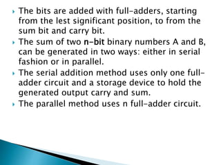
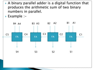


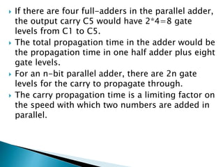


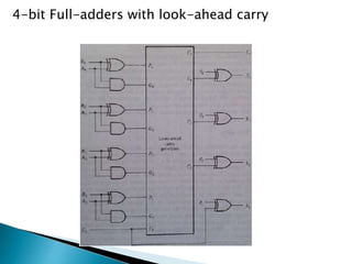


The document discusses binary parallel adders and carry propagation in digital circuits. It explains that a binary parallel adder produces the sum of two n-bit binary numbers using n full-adder circuits in parallel. The longest delay in a parallel adder is the time it takes for the carry to propagate through the full-adder circuits. Various techniques are presented to reduce carry propagation delay, including employing faster gates, increasing complexity to provide shorter paths for the carry, and using look-ahead carry circuits which can pre-compute carry bits to reduce delay.