Downloaded 1,466 times

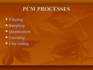
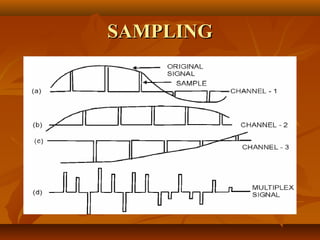
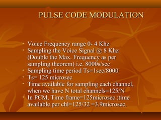
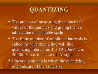
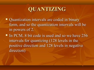


Pulse code modulation (PCM) involves sampling an analog signal at regular intervals, quantizing the sample values, and encoding the samples as digital code. The analog voice signal is sampled 8000 times per second, with each sample represented by an 8-bit binary number. This results in a digital data rate of 64,000 bits per second to represent the original voice signal. Quantization assigns the sample values to discrete levels, introducing quantization error between the original and encoded signals.