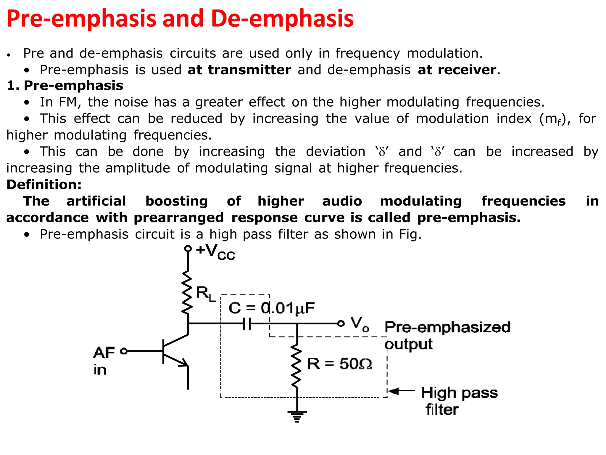
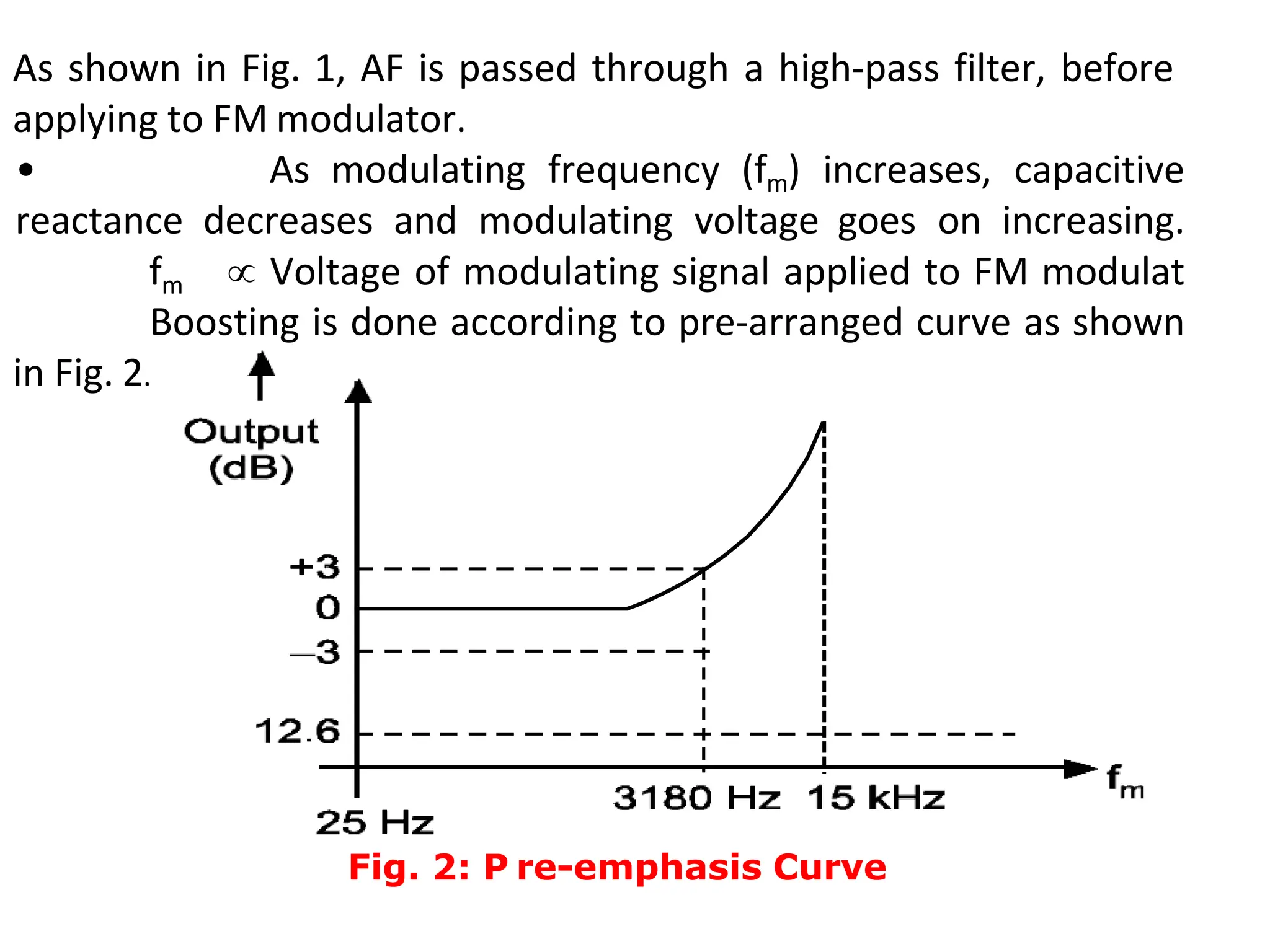
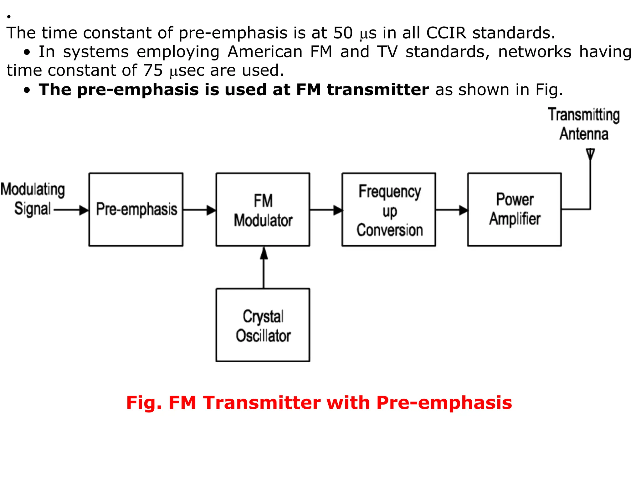
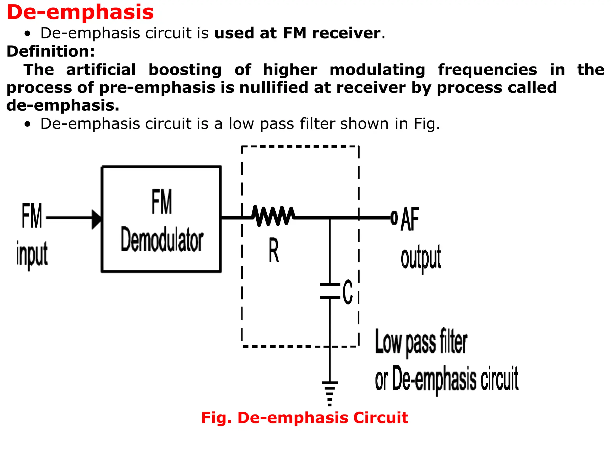
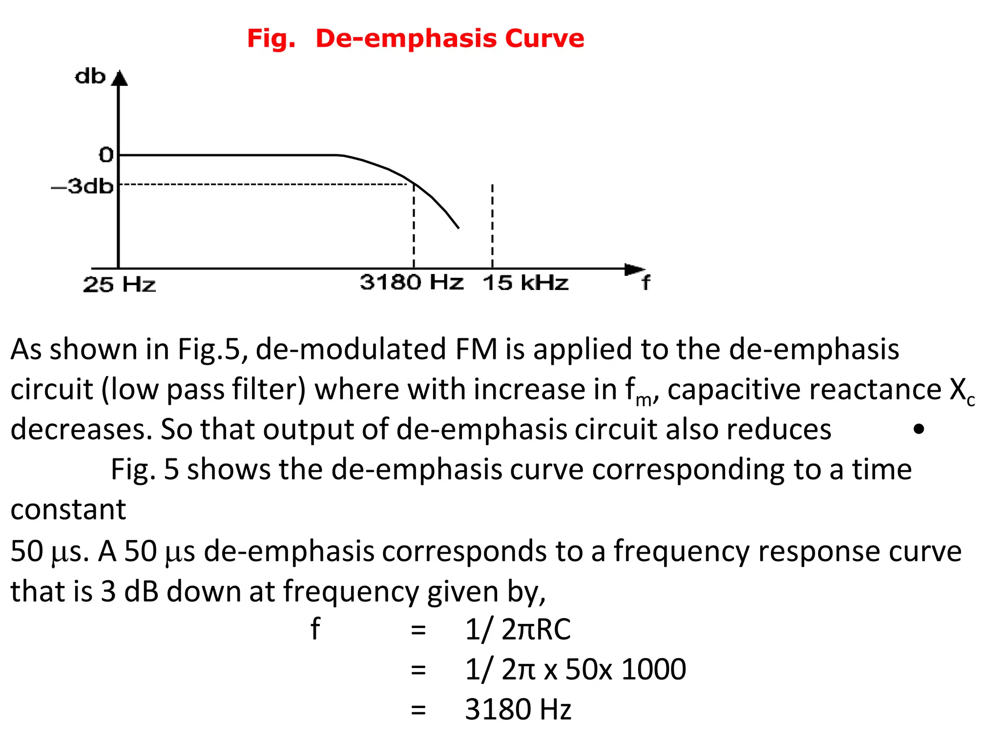
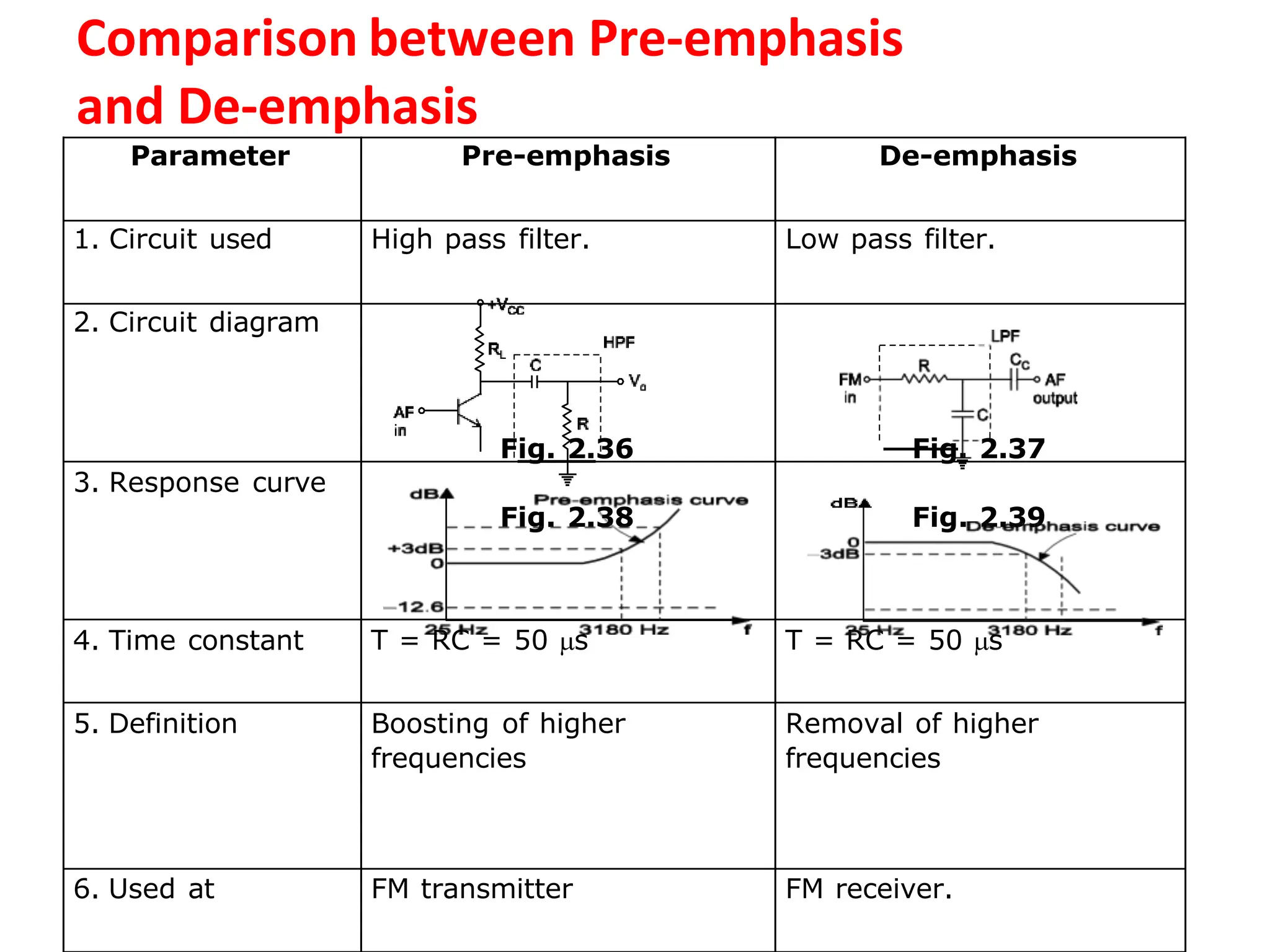
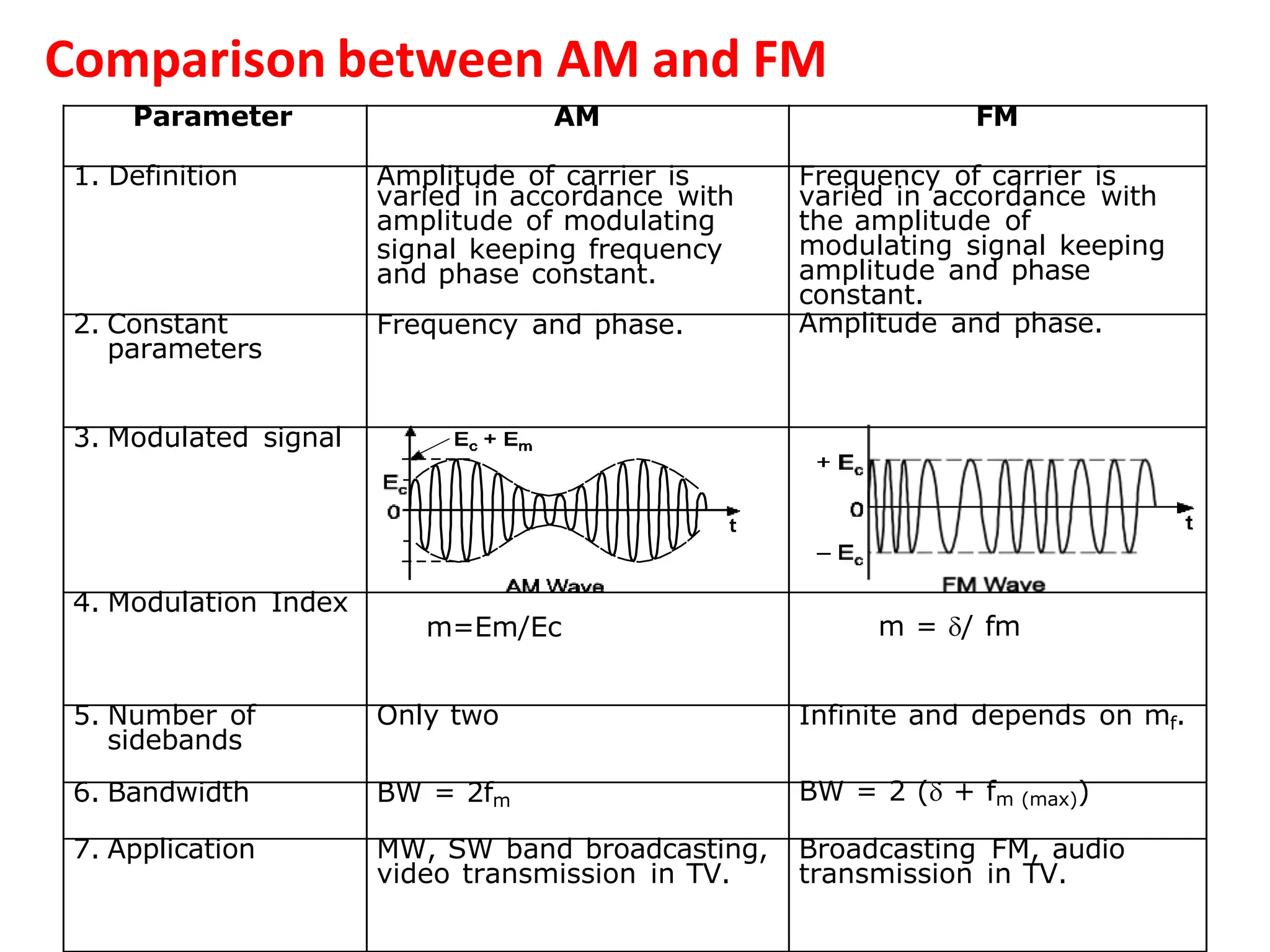
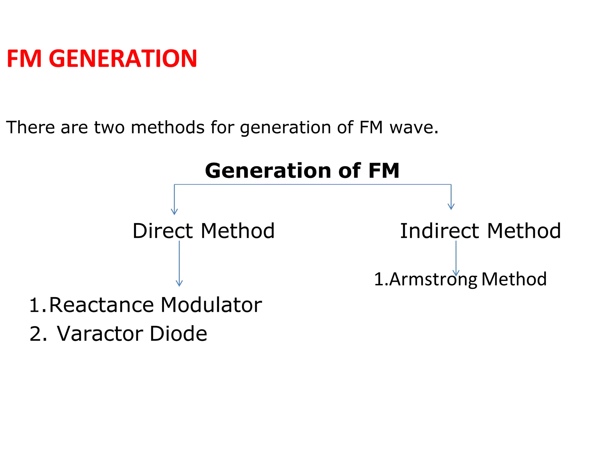
ANALOG COMMUNICATION SYSTEMS
By
Ms. Swati S Halunde
DEPT. of E.C.E
SITCOE, Yadrav
Types of Frequency Modulation
FM (Frequency Modulation)
NarrowbandFM
(NBFM)
[Whenmodulationindex is small]
WidebandFM
(WBFM)
[Whenmodulationindexis large]
Comparison between Narrowband
and Wideband FM
Sr.
No.
Parameter NBFM WBFM
1. Modulation
index
Less than or slightly
greater than 1
Greater than 1
2. Maximum
deviation
5 kHz 75 kHz
3. Range of
modulating
frequency
20 Hz to 3 kHz 20 Hz to 15 kHz
4. Maximum
modulation
index
Slightly greater than 1 5 to 2500
5. Bandwidth Small approximately
same as that of AM
BW = 2fm
Large about 15 times
greater than that of
NBFM.
BW = 2(+fmmax)
6. Applications FM mobile communication
like police wireless,
ambulance, short range
ship to shore
communication etc.
Entertainment
broadcasting (can be used
for high quality music
transmission)
Representation of FM
FM can be represented by two ways:
1. Time domain.
2. Frequency domain.
1.FM in Time Domain
Time domain representation means continuous variation of voltage with respect
to time as shown in Fig. .
Fig. 1 FM in Time Domain
2.FM in Frequency Domain
• Frequency domain is also known as frequency spectrum.
• FM in frequency domain means graph or plot of amplitude versus frequency as
shown in Fig. 2.29.
Fig. 2: FM in Frequency Domain
Pre-emphasis and De-emphasis
• Pre and de-emphasis circuits are used only in frequency modulation.
• Pre-emphasis is used at transmitter and de-emphasis at receiver.
1. Pre-emphasis
• In FM, the noise has a greater effect on the higher modulating frequencies.
• This effect can be reduced by increasing the value of modulation index (mf), for
higher modulating frequencies.
• This can be done by increasing the deviation ‘’ and ‘’ can be increased by
increasing the amplitude of modulating signal at higher frequencies.
Definition:
The artificial boosting of higher audio modulating frequencies in
accordance with prearranged response curve is called pre-emphasis.
• Pre-emphasis circuit is a high pass filter as shown in Fig.
As shown in Fig. 1, AF is passed through a high-pass filter, before
applying to FM modulator.
• As modulating frequency (fm) increases, capacitive
reactance decreases and modulating voltage goes on increasing.
fm  Voltage of modulating signal applied to FM modulat
Boosting is done according to pre-arranged curve as shown
in Fig. 2.
Fig. 2: P re-emphasis Curve
•
The time constant of pre-emphasis is at 50 s in all CCIR standards.
• In systems employing American FM and TV standards, networks having
time constant of 75 sec are used.
• The pre-emphasis is used at FM transmitter as shown in Fig.
Fig. FM Transmitter with Pre-emphasis
De-emphasis
• De-emphasis circuit is used at FM receiver.
Definition:
The artificial boosting of higher modulating frequencies in the
process of pre-emphasis is nullified at receiver by process called
de-emphasis.
• De-emphasis circuit is a low pass filter shown in Fig.
Fig. De-emphasis Circuit
Fig. De-emphasis Curve
As shown in Fig.5, de-modulated FM is applied to the de-emphasis
circuit (low pass filter) where with increase in fm, capacitive reactance Xc
decreases. So that output of de-emphasis circuit also reduces •
Fig. 5 shows the de-emphasis curve corresponding to a time
constant
50 s. A 50 s de-emphasis corresponds to a frequency response curve
that is 3 dB down at frequency given by,
f = 1/ 2πRC
= 1/ 2π x 50x 1000
= 3180 Hz
Comparison between Pre-emphasis
and De-emphasis
Parameter Pre-emphasis De-emphasis
1. Circuit used High pass filter. Low pass filter.
2. Circuit diagram
Fig. 2.36 Fig. 2.37
3. Response curve
Fig. 2.38 Fig. 2.39
4. Time constant T = RC = 50 s T = RC = 50 s
5. Definition Boosting of higher
frequencies
Removal of higher
frequencies
6. Used at FM transmitter FM receiver.
Comparison between AM and FM
Parameter AM FM
1. Definition Amplitude of carrier is Frequency of carrier is
2. Constant
varied in accordance with
amplitude of modulating
signal keeping frequency
and phase constant.
Frequency and phase.
varied in accordance with
the amplitude of
modulating signal keeping
amplitude and phase
constant.
Amplitude and phase.
parameters
3. Modulated signal
4. Modulation Index
m=Em/Ec m = / fm
5. Number of Only two Infinite and depends on mf.
sidebands
6. Bandwidth BW = 2fm BW = 2 ( + fm (max))
7. Application MW, SW band broadcasting,
video transmission in TV.
Broadcasting FM, audio
transmission in TV.
FM GENERATION
There are two methods for generation of FM wave.
Generation of FM
Direct Method Indirect Method
1.Armstrong Method
1.Reactance Modulator
2. Varactor Diode
Reactance Method
Fig. : Transistorized Reactance Modulator
Varactor Diode Modulator
Fig. : Varactor Diode Frequency Modulator
Limitations of Direct Method of FM Generation
1. In this method, it is very difficult to get high order
stability in carrier frequency because in this method the
basic oscillator is not a stable oscillator, as it is controlled by
the modulating signal.
2.Generally in this method we get distorted FM, due
to non-linearity of the varactor diode.
FM Transmitter (Armstrong Method)
FM Generation using IC 566
Fig. : Basic Frequency Modulator using NE566 VCO
Advantages/ Disadvantages/Applications of FM
Advantages of FM
1.Transmitted power remains constant.
2.FM receivers are immune to noise.
3.Good capture effect.
4.No mixing of signals.
Disadvantages of FM
The greatest disadvantages of FM are:
1.It uses too much spectrum space.
2.The bandwidth is wider.
3.The modulation index can be kept low to minimize the
bandwidth used.
4.But reduction in M.I. reduces the noise immunity.
5.Used only at very high frequencies.
Applications of FM
1.FM radio broadcasting.
2.Sound transmission in TV.
3.Police wireless.
Demodulation of FM Signal
Two steps involved in FM demodulation
•Conversion of FM signal into AM signal, Tank or
parallel resonance circuit converts FM into AM
signal.
•An envelope detector is used to extract
modulating signal from modulated signal.
Slope Demodulator:

Frequency modulation and demodulation along with types

  • 1.
    ANALOG COMMUNICATION SYSTEMS By Ms.Swati S Halunde DEPT. of E.C.E SITCOE, Yadrav
  • 2.
    Types of FrequencyModulation FM (Frequency Modulation) NarrowbandFM (NBFM) [Whenmodulationindex is small] WidebandFM (WBFM) [Whenmodulationindexis large]
  • 3.
    Comparison between Narrowband andWideband FM Sr. No. Parameter NBFM WBFM 1. Modulation index Less than or slightly greater than 1 Greater than 1 2. Maximum deviation 5 kHz 75 kHz 3. Range of modulating frequency 20 Hz to 3 kHz 20 Hz to 15 kHz 4. Maximum modulation index Slightly greater than 1 5 to 2500 5. Bandwidth Small approximately same as that of AM BW = 2fm Large about 15 times greater than that of NBFM. BW = 2(+fmmax) 6. Applications FM mobile communication like police wireless, ambulance, short range ship to shore communication etc. Entertainment broadcasting (can be used for high quality music transmission)
  • 4.
    Representation of FM FMcan be represented by two ways: 1. Time domain. 2. Frequency domain. 1.FM in Time Domain Time domain representation means continuous variation of voltage with respect to time as shown in Fig. . Fig. 1 FM in Time Domain 2.FM in Frequency Domain • Frequency domain is also known as frequency spectrum. • FM in frequency domain means graph or plot of amplitude versus frequency as shown in Fig. 2.29. Fig. 2: FM in Frequency Domain
  • 5.
    Pre-emphasis and De-emphasis •Pre and de-emphasis circuits are used only in frequency modulation. • Pre-emphasis is used at transmitter and de-emphasis at receiver. 1. Pre-emphasis • In FM, the noise has a greater effect on the higher modulating frequencies. • This effect can be reduced by increasing the value of modulation index (mf), for higher modulating frequencies. • This can be done by increasing the deviation ‘’ and ‘’ can be increased by increasing the amplitude of modulating signal at higher frequencies. Definition: The artificial boosting of higher audio modulating frequencies in accordance with prearranged response curve is called pre-emphasis. • Pre-emphasis circuit is a high pass filter as shown in Fig.
  • 6.
    As shown inFig. 1, AF is passed through a high-pass filter, before applying to FM modulator. • As modulating frequency (fm) increases, capacitive reactance decreases and modulating voltage goes on increasing. fm  Voltage of modulating signal applied to FM modulat Boosting is done according to pre-arranged curve as shown in Fig. 2. Fig. 2: P re-emphasis Curve
  • 7.
    • The time constantof pre-emphasis is at 50 s in all CCIR standards. • In systems employing American FM and TV standards, networks having time constant of 75 sec are used. • The pre-emphasis is used at FM transmitter as shown in Fig. Fig. FM Transmitter with Pre-emphasis
  • 8.
    De-emphasis • De-emphasis circuitis used at FM receiver. Definition: The artificial boosting of higher modulating frequencies in the process of pre-emphasis is nullified at receiver by process called de-emphasis. • De-emphasis circuit is a low pass filter shown in Fig. Fig. De-emphasis Circuit
  • 9.
    Fig. De-emphasis Curve Asshown in Fig.5, de-modulated FM is applied to the de-emphasis circuit (low pass filter) where with increase in fm, capacitive reactance Xc decreases. So that output of de-emphasis circuit also reduces • Fig. 5 shows the de-emphasis curve corresponding to a time constant 50 s. A 50 s de-emphasis corresponds to a frequency response curve that is 3 dB down at frequency given by, f = 1/ 2πRC = 1/ 2π x 50x 1000 = 3180 Hz
  • 10.
    Comparison between Pre-emphasis andDe-emphasis Parameter Pre-emphasis De-emphasis 1. Circuit used High pass filter. Low pass filter. 2. Circuit diagram Fig. 2.36 Fig. 2.37 3. Response curve Fig. 2.38 Fig. 2.39 4. Time constant T = RC = 50 s T = RC = 50 s 5. Definition Boosting of higher frequencies Removal of higher frequencies 6. Used at FM transmitter FM receiver.
  • 11.
    Comparison between AMand FM Parameter AM FM 1. Definition Amplitude of carrier is Frequency of carrier is 2. Constant varied in accordance with amplitude of modulating signal keeping frequency and phase constant. Frequency and phase. varied in accordance with the amplitude of modulating signal keeping amplitude and phase constant. Amplitude and phase. parameters 3. Modulated signal 4. Modulation Index m=Em/Ec m = / fm 5. Number of Only two Infinite and depends on mf. sidebands 6. Bandwidth BW = 2fm BW = 2 ( + fm (max)) 7. Application MW, SW band broadcasting, video transmission in TV. Broadcasting FM, audio transmission in TV.
  • 12.
    FM GENERATION There aretwo methods for generation of FM wave. Generation of FM Direct Method Indirect Method 1.Armstrong Method 1.Reactance Modulator 2. Varactor Diode
  • 13.
    Reactance Method Fig. :Transistorized Reactance Modulator
  • 14.
    Varactor Diode Modulator Fig.: Varactor Diode Frequency Modulator
  • 15.
    Limitations of DirectMethod of FM Generation 1. In this method, it is very difficult to get high order stability in carrier frequency because in this method the basic oscillator is not a stable oscillator, as it is controlled by the modulating signal. 2.Generally in this method we get distorted FM, due to non-linearity of the varactor diode.
  • 16.
  • 17.
    FM Generation usingIC 566 Fig. : Basic Frequency Modulator using NE566 VCO
  • 18.
    Advantages/ Disadvantages/Applications ofFM Advantages of FM 1.Transmitted power remains constant. 2.FM receivers are immune to noise. 3.Good capture effect. 4.No mixing of signals. Disadvantages of FM The greatest disadvantages of FM are: 1.It uses too much spectrum space. 2.The bandwidth is wider. 3.The modulation index can be kept low to minimize the bandwidth used. 4.But reduction in M.I. reduces the noise immunity. 5.Used only at very high frequencies. Applications of FM 1.FM radio broadcasting. 2.Sound transmission in TV. 3.Police wireless.
  • 19.
    Demodulation of FMSignal Two steps involved in FM demodulation •Conversion of FM signal into AM signal, Tank or parallel resonance circuit converts FM into AM signal. •An envelope detector is used to extract modulating signal from modulated signal. Slope Demodulator: