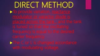
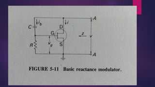
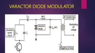
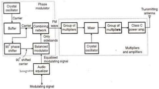
GENERATION OF FM
SUBMITTED BY,
B.KAAVYA
Basic requirements to produce FM
Variable output frequency with the
variation proportional to the
instantaneous amplitude of the
modulating voltage.
The amplitude of the carrier remains
constant during modulation.
HOW FM IS GENERATED?
If either the capacitance or
inductance of an LC oscillator tank is
varied, FM is generated.
Two methods:
1. Direct method
2. Indirect method
DIRECT METHOD
To provide variation, reactance
modulator or varactor diode is
placed across the tank , and the tank
is tuned so that the oscillating
frequency is equal to the desired
carrier frequency.
The C or L is changed accordance
with modulating voltage.
FET Reactance
Modulator
3 terminal reactance that can be
connected across tank circuit.
The value of this reactance is
proportional to the
trasconductance of the device.
THEORY
To determine Z, a voltage ‘v’ is
applied to the terminals A-A
between which the impedance is
to be measured, and the
resulting current ‘I’ is calculated
Impedance to be a pure reactance two
requirements must be fulfilled.
 1. Bias network current ‘ib’ must be
negligible compared to the drain
current.
 2. Drain to gate impedance (Xc) must
be greater than the gate to source
impedance (R).
Ceq = gmRC
Ceq depends on device gm and can
be varied with bias voltage.
Capacitance can be adjusted by
varying the components R and C.
This expression has the correct
dimensions of capacitance.
Xc > R
If R is not << than Xc the Vg
will no longer be exactly 90° out
of phase with the ‘v’.
Thus the input impedance will
no longer be purely reactive.
The gate to drain impedance is, in
practice made five to ten times the
gate to source impedance.
Let Xc = nR (at the carrier frequency)
in the capacitive RC reactance FET.
4 Different Arrangements
of Reactance Modulator
 In all arrangements drain current must be
much greater than bias network current.
Commonly used oscillators:
1. Hartley oscillator
2. Colpitts (Clapp Gouriet) an RC
capacitive transistor reactance
modulator operates on tank circit.
VARACTOR DIODE
Junction capacitance varies linearly
with the applied voltage when the
diode is reverse biased.
It is employed together with a
reactance modulator to provide
automatic frequency correction for an
FM transmitter.
This diode is back biased to provide
the junction capacitance(capacitance
associated with charge variation in the
depletion layer) effect.
This bias is varied by the modulating
voltage which is in series with it.
It is often used for automatic
frequency control and remote tuning.
VARACTOR DIODE MODULATOR
INDIRECT METHOD
Generating FM through phase
modulation , where a crystal oscillator
can be used.
Operating frequency for crystal
oscillator and phase modulator is
1MHz.
Armstrong system
Crystal oscillator: It is an electronic oscillator
circuit that uses the mechanical resonance of
a vibrating crystal of piezoelectric material
to create an electrical signal with a precise
frequency.
Phase modulation: It encodes a message
signal as variations in the instantaneous
phase of a carrier wave.
BLOCK DIAGRAM EXPLANATION
The effect of mixing on an FM
signal is to change the center
frequency only.
The effect of frequency
multiplication is to multiply center
frequency and deviation equally.
Frequency mixer: A nonlinear
electrical circuit that creates new
frequencies from two signals applied
to it.
Frequency multiplier: An electronic
circuit that generates an output
signal whose output frequency is a
harmonic of its input frequency.
PHASE MODULATION VECTOR
DIAGRAMS
DIAGRAM 1
The resultant of two sideband
frequency vectors is always in phase
with the unmodulated carrier vector.
So there is a phase change of 90° of
sideband voltages with carrier vector.
DIAGRAM 2
If an amplitude modulated
voltage is added to an
unmodulated voltage of the
same frequency and the two
are kept 90° apart in phase.
DIAGRAM 3
The carrier of the amplitude modulated
signal has been removed so that only the two
sidebands are added to unmodulated
voltage.
The resultant of the 2 sideband voltages will
always be in quadrature with the carrier
voltage.
Modulation↑ phase deviation ↑ hence phase
modulation is obtained
The resultant voltage will be phase
modulated but with little amplitude
modulation also.
If amplitude limiter is used then there will be
phase modulation only.
The modulating voltage will have to be
equalized before it enters the balanced
modulator.
The modulating voltage will have to
be equalized before it enters the
balanced modulator.
In FM broadcasting,ῳL =R at 30Hz.
As frequency increases above that
the output of the equalizer will fall at
a rate of 6dB/octave.
Effects of frequency changing on
an FM signal
Armstrong system is often used with
reactance modulator.
Modulation index is multiplied by
the same factor as the center
frequency.
If a frequency modulated signal fc is
fed to a frequency doubler, the output
signal will contain twice each input
frequency. (2fc±2 )
When a frequency modulated wave is
mixed with frequency f0 then output will
be fc-f0- and fc-f0+ .
Maximum frequency is a .
Modulating frequency has remained
constant in both cases.
But the modulating index will be
affected.
It is possible to raise the modulation
index without affecting the center
frequency by multiplying both by 9 and
mixing the result with a frequency 8
times the original frequency.
Characteristics of Phase
modulation
Angle of phase modulation is
proportional to the amplitude of the
modulating voltage not the angle.
To keep the angle of deviation small
both mixing and multiplication must
be done.
For broadcast purpose,
operating frequency is 180MHz
with initial fc=1MHz and
=60Hz.
Hence a deviation 10.8kHz at
180MHz is achieved and that is
adequate for FM mobile
network.
Generation of fm
Generation of fm

Generation of fm

  • 1.
  • 2.
    Basic requirements toproduce FM Variable output frequency with the variation proportional to the instantaneous amplitude of the modulating voltage. The amplitude of the carrier remains constant during modulation.
  • 5.
    HOW FM ISGENERATED? If either the capacitance or inductance of an LC oscillator tank is varied, FM is generated. Two methods: 1. Direct method 2. Indirect method
  • 6.
    DIRECT METHOD To providevariation, reactance modulator or varactor diode is placed across the tank , and the tank is tuned so that the oscillating frequency is equal to the desired carrier frequency. The C or L is changed accordance with modulating voltage.
  • 8.
    FET Reactance Modulator 3 terminalreactance that can be connected across tank circuit. The value of this reactance is proportional to the trasconductance of the device.
  • 9.
    THEORY To determine Z,a voltage ‘v’ is applied to the terminals A-A between which the impedance is to be measured, and the resulting current ‘I’ is calculated
  • 10.
    Impedance to bea pure reactance two requirements must be fulfilled.  1. Bias network current ‘ib’ must be negligible compared to the drain current.  2. Drain to gate impedance (Xc) must be greater than the gate to source impedance (R).
  • 11.
    Ceq = gmRC Ceqdepends on device gm and can be varied with bias voltage. Capacitance can be adjusted by varying the components R and C. This expression has the correct dimensions of capacitance. Xc > R
  • 12.
    If R isnot << than Xc the Vg will no longer be exactly 90° out of phase with the ‘v’. Thus the input impedance will no longer be purely reactive.
  • 13.
    The gate todrain impedance is, in practice made five to ten times the gate to source impedance. Let Xc = nR (at the carrier frequency) in the capacitive RC reactance FET.
  • 14.
    4 Different Arrangements ofReactance Modulator
  • 15.
     In allarrangements drain current must be much greater than bias network current. Commonly used oscillators: 1. Hartley oscillator 2. Colpitts (Clapp Gouriet) an RC capacitive transistor reactance modulator operates on tank circit.
  • 16.
    VARACTOR DIODE Junction capacitancevaries linearly with the applied voltage when the diode is reverse biased. It is employed together with a reactance modulator to provide automatic frequency correction for an FM transmitter.
  • 17.
    This diode isback biased to provide the junction capacitance(capacitance associated with charge variation in the depletion layer) effect. This bias is varied by the modulating voltage which is in series with it. It is often used for automatic frequency control and remote tuning.
  • 18.
  • 19.
    INDIRECT METHOD Generating FMthrough phase modulation , where a crystal oscillator can be used. Operating frequency for crystal oscillator and phase modulator is 1MHz. Armstrong system
  • 20.
    Crystal oscillator: Itis an electronic oscillator circuit that uses the mechanical resonance of a vibrating crystal of piezoelectric material to create an electrical signal with a precise frequency. Phase modulation: It encodes a message signal as variations in the instantaneous phase of a carrier wave.
  • 23.
    BLOCK DIAGRAM EXPLANATION Theeffect of mixing on an FM signal is to change the center frequency only. The effect of frequency multiplication is to multiply center frequency and deviation equally.
  • 24.
    Frequency mixer: Anonlinear electrical circuit that creates new frequencies from two signals applied to it. Frequency multiplier: An electronic circuit that generates an output signal whose output frequency is a harmonic of its input frequency.
  • 25.
  • 26.
    DIAGRAM 1 The resultantof two sideband frequency vectors is always in phase with the unmodulated carrier vector. So there is a phase change of 90° of sideband voltages with carrier vector.
  • 27.
    DIAGRAM 2 If anamplitude modulated voltage is added to an unmodulated voltage of the same frequency and the two are kept 90° apart in phase.
  • 28.
    DIAGRAM 3 The carrierof the amplitude modulated signal has been removed so that only the two sidebands are added to unmodulated voltage. The resultant of the 2 sideband voltages will always be in quadrature with the carrier voltage. Modulation↑ phase deviation ↑ hence phase modulation is obtained
  • 29.
    The resultant voltagewill be phase modulated but with little amplitude modulation also. If amplitude limiter is used then there will be phase modulation only. The modulating voltage will have to be equalized before it enters the balanced modulator.
  • 30.
    The modulating voltagewill have to be equalized before it enters the balanced modulator. In FM broadcasting,ῳL =R at 30Hz. As frequency increases above that the output of the equalizer will fall at a rate of 6dB/octave.
  • 32.
    Effects of frequencychanging on an FM signal Armstrong system is often used with reactance modulator. Modulation index is multiplied by the same factor as the center frequency.
  • 33.
    If a frequencymodulated signal fc is fed to a frequency doubler, the output signal will contain twice each input frequency. (2fc±2 ) When a frequency modulated wave is mixed with frequency f0 then output will be fc-f0- and fc-f0+ . Maximum frequency is a .
  • 34.
    Modulating frequency hasremained constant in both cases. But the modulating index will be affected. It is possible to raise the modulation index without affecting the center frequency by multiplying both by 9 and mixing the result with a frequency 8 times the original frequency.
  • 35.
    Characteristics of Phase modulation Angleof phase modulation is proportional to the amplitude of the modulating voltage not the angle. To keep the angle of deviation small both mixing and multiplication must be done.
  • 36.
    For broadcast purpose, operatingfrequency is 180MHz with initial fc=1MHz and =60Hz. Hence a deviation 10.8kHz at 180MHz is achieved and that is adequate for FM mobile network.