Downloaded 70 times

![Definition
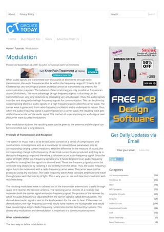
The method of varying amplitude of a high frequency carrier wave in accordance with the
information to be transmitted, keeping the frequency and phase of the carrier wave
unchanged is called Amplitude Modulation. The information is considered as the modulating
signal and it is superimposed on the carrier wave by applying both of them to the modulator.
The detailed diagram showing the amplitude modulation process is given below.
Amplitude Modulation
As shown above, the carrier wave has positive and negative half cycles. Both these cycles are
varied according to the information to be sent. The carrier then consists of sine waves whose
amplitudes follow the amplitude variations of the modulating wave. The carrier is kept in an
envelope formed by the modulating wave. From the figure, you can also see that the
amplitude variation of the high frequency carrier is at the signal frequency and the frequency
of the carrier wave is the same as the frequency of the resulting wave.
Analysis of Amplitude Modulation Carrier Wave
Let v = V Sin w t
v = V Sin w t
v – Instantaneous value of the carrier
V – Peak value of the carrier
W – Angular velocity of the carrier
v – Instantaneous value of the modulating signal
V – Maximum value of the modulating signal
w – Angular velocity of the modulating signal
f – Modulating signal frequency
It must be noted that the phase angle remains constant in this process. Thus it can be
ignored. The amplitude of the carrier wave varies at f .
The amplitude modulated wave is given by the equation
A = V + v = V + V Sin w t = V [1+ (V /V Sin w t)]
= V (1 + mSin w t)
m – Modulation Index. The ratio of V /V .
Instantaneous value of amplitude modulated wave is given by the equation
c c c
m m m
c
c
c
m
m
m
m
m
c m c m m c m c m
c m
m c
(3)Proximity Detectors
(30)Radio Circuits
(19)Radio Transmitters
(1)Raspberry Pi
(3)Relays
(12)Remote Circuits
(4)Reviews
(6)Robotics
(2)RTOS
(16)Security & Saftey
(16)Sensor Circuits
(11)Signal Conditioners
(13)Signal Generators
(1)Speed Controller Circuits
(2)State space analysis
(6)Switching Circuits
(87)Tech News
(9)Telephone Related
(4)Television Related
(3)Temperature Related
(38)Test & Measurement Circuits
(9)Testing Components
(1)Three phase circuits
(3)Timer Circuits
(20)Tone generator circuits
(5)Tools and Softwares
(7)Transmitters
(158)Tutorials
(2)UPS
(3)USB Circuits
(5)Videos
(36)VLSI
(15)Voltage Regulators
Latest Articles
GSM based SMS Alert Fire Alarm System
using Arduino
Simple RFID based Door Lock using Arduino
Interfacing RFID with Arduino – How to Read
RFID Cards using Arduino
How to Interface GSM Module and Arduino-
Send and Receive SMS
Frequency counter using arduino
IPCA Electronics Expo 2015 – Revolutionizing
the Make in India campaign
Interfacing pressure sensor to arduino
We Are Launching An Online Store to Shop](https://image.slidesharecdn.com/modulation-types-amplitudefrequencyphasemodulation-150423114806-conversion-gate01/85/Modulation-types-amplitude-frequency-phase-modulation-3-320.jpg)
![v = A Sin w t = Vc (1 + m Sin w t) Sin wct
= V Sin w t + mVc (Sin w t Sin w t)
v = V Sin wct + [mV /2 Cos (wc-wm)t – mVc/2 Cos (wc + wm)t]
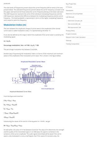
The above equation represents the sum of three sine waves. One with amplitude of Vc and a
frequency of w /2 , the second one with an amplitude of mV /2 and frequency of (w – w )/2
and the third one with an amplitude of mV /2 and a frequency of (w + w )/2 .
In practice the angular velocity of the carrier is known to be greater than the angular velocity
of the modulating signal (w >> w ). Thus, the second and third cosine equations are more
close to the carrier frequency. The equation is represented graphically as shown below.
Amplitude Modulation Frequency Spectrum
Frequency Spectrum of AM Wave
Lower side frequency – (w – w )/2
Upper side frequency – (w +w )/2
The frequency components present in the AM wave are represented by vertical lines
approximately located along the frequency axis. The height of each vertical line is drawn in
proportion to its amplitude. Since the angular velocity of the carrier is greater than the
angular velocity of the modulating signal, the amplitude of side band frequencies can never
exceed half of the carrier amplitude.
Thus there will not be any change in the original frequency, but the side band frequencies (w
– w )/2 and (w +w )/2 will be changed. The former is called the upper side band (USB)
frequency and the later is known as lower side band (LSB) frequency.
Since the signal frequency w /2 is present in the side bands, it is clear that the carrier
voltage component does not transmit any information.
Two side banded frequencies will be produced when a carrier is amplitude modulated by a
single frequency. That is, an AM wave has a band width from (w – w )/2 to (w +w )/2 , that
is, 2w /2 or twice the signal frequency is produced. When a modulating signal has more
than one frequency, two side band frequencies are produced by every frequency. Similarly
for two frequencies of the modulating signal 2 LSB’s and 2 USB’s frequencies will be
c m
c c m c
c c
c c c m
c c m
c m
c m
c m
c
m c m
m
c m c m
m
Electronic Kits,Boards and Components
Digital Code Lock using Arduino with LCD
Display and User Defined Password
The Big List of Arduino Projects and Circuits
Like Us on Facebook
Circuitstoday.com
27,022 people like Circuitstoday.com.
Facebook social plugin
Like
Recent Comments
jojo on Simple RFID based Door Lock using
Arduino
jojo on Digital code lock using arduino
jojo on Digital code lock using arduino
ijaz on Interfacing 16×2 LCD with 8051
Srihari Rao M on Line Follower Robot using
Arduino
Yashas on Digital code lock using arduino
prabhakar reddy on Embedded Systems
Career-An Outline
Mandar Kholgade on Interfacing Seven
segment display to 8051
hamid on Heart rate monitor using 8051
pathik on Simple Lamp Dimmer/ Fan
Regulator
Atharva.muraskar on Electronic mosquito
repeller
miraat on Temperature controlled DC fan
Raymond Tan on Heart rate monitor using
8051
Raymond Tan on Heart rate monitor using
8051
Rohith N on Water Level Controller using
8051
Pages
About
Advertise With Us
Authors](https://image.slidesharecdn.com/modulation-types-amplitudefrequencyphasemodulation-150423114806-conversion-gate01/85/Modulation-types-amplitude-frequency-phase-modulation-4-320.jpg)
![You may also like:
Resistor Color Code Chart – Understanding Resistance Color Coding
How to debug in Keil Microvision
Getting Started with Keil uVision
Bit rate Vs Baud rate – the common misconception
How to recover/reset admin username and password of Vbulletin forum software
Tagged
transmitter output produces erroneous distortion.
Power Relations in an AM wave
A modulated wave has more power than had by the carrier wave before modulating. The
total power components in amplitude modulation can be written as:
P = P + P + P
Considering additional resistance like antenna resistance R.
P = [(V /√2)/R] = V /2R
Each side band has a value of m/2 V and r.m.s value of mV /2√2. Hence power in LSB and
USB can be written as
P = P = (mV /2√2) /R = m /4*V C/2R = m /4 P
P = V /2R + [m /4*V C/2R] + [m /4*V C/2R] = V /2R (1 + m /2) = P (1 + m /2)
In some applications, the carrier is simultaneously modulated by several sinusoidal
modulating signals. In such a case, the total modulation index is given as
Mt = √(m1 + m2 + m3 + m4 + …..)
If Ic and It are the r.m.s values of unmodulated current and total modulated current and R is
the resistance through which these current flow, then
P /P = (It.R/Ic.R) = (It/Ic)
P /P = (1 + m /2)
It/Ic = 1 + m /2
Limitations of Amplitude Modulation
1. Low Efficiency- Since the useful power that lies in the small bands is quite small, so the
efficiency of AM system is low.
2. Limited Operating Range – The range of operation is small due to low efficiency. Thus,
transmission of signals is difficult.
3. Noise in Reception – As the radio receiver finds it difficult to distinguish between the
amplitude variations that represent noise and those with the signals, heavy noise is
prone to occur in its reception.
4. Poor Audio Quality – To obtain high fidelity reception, all audio frequencies till 15
KiloHertz must be reproduced and this necessitates the bandwidth of 10 KiloHertz to
minimise the interference from the adjacent broadcasting stations. Therefore in AM
broadcasting stations audio quality is known to be poor.
total carrier LSB USB
carrier c
2 2
C
c c
LSB USB c
2 2 2
2 carrier
total
2
C
2 2 2 2 2
C
2
carrier
2
2 2 2 2
total carrier
2 2
total carrier
2
2
Tutorials
Electronics In Jaipur
Want To Buy Used Electronic Items? Get TV,Kettles,Inverters
Only@Askme](https://image.slidesharecdn.com/modulation-types-amplitudefrequencyphasemodulation-150423114806-conversion-gate01/85/Modulation-types-amplitude-frequency-phase-modulation-6-320.jpg)


Modulation is the process of varying a high frequency carrier wave by an audio signal to allow audio transmission over long distances. In amplitude modulation (AM), the amplitude of the carrier wave is varied in proportion to the amplitude of the audio signal while keeping the carrier frequency and phase constant. This generates sideband frequencies above and below the carrier frequency that contain the audio information. The bandwidth of an AM signal is equal to twice the highest audio frequency. Modulation allows audio signals to be combined with high frequency radio waves for effective long-distance radio communication.


![Attack surfaces and attack tress[inform]](https://cdn.slidesharecdn.com/ss_thumbnails/lecture03-260108015941-a4dee53b-thumbnail.jpg?width=640&height=640&fit=bounds)