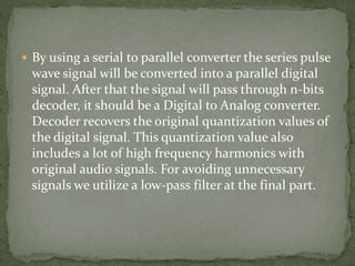
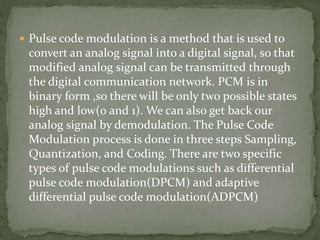
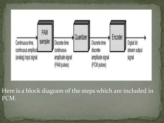
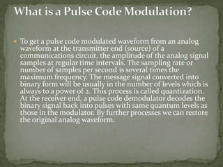
(TARA) Talegaon Dabhade Call Girls Just Call 7001035870 [ Cash on Delivery ] ...
Pulse code modulation (PCM)
1. Prepared BY :- Mahima Shastri
Enroll no. :- 170050111022
Branch :- EC (Sem 6)
Sub :- DCOM
Topic :- Pulse Code Modulation (PCM)
2. Pulse code modulation is a method that is used to
convert an analog signal into a digital signal, so that
modified analog signal can be transmitted through
the digital communication network. PCM is in
binary form ,so there will be only two possible states
high and low(0 and 1). We can also get back our
analog signal by demodulation. The Pulse Code
Modulation process is done in three steps Sampling,
Quantization, and Coding. There are two specific
types of pulse code modulations such as differential
pulse code modulation(DPCM) and adaptive
differential pulse code modulation(ADPCM)
3. Here is a block diagram of the steps which are included in
PCM.
4. To get a pulse code modulated waveform from an analog
waveform at the transmitter end (source) of a
communications circuit, the amplitude of the analog signal
samples at regular time intervals. The sampling rate or
number of samples per second is several times the
maximum frequency. The message signal converted into
binary form will be usually in the number of levels which is
always to a power of 2. This process is called quantization.
At the receiver end, a pulse code demodulator decodes the
binary signal back into pulses with same quantum levels as
those in the modulator. By further processes we can restore
the original analog waveform.
5.
6. Sampling is a process of measuring the amplitude of a
continuous-time signal at discrete instants, converts
the continuous signal into a discrete signal. For
example, conversion of a sound wave to a sequence of
samples. The Sample is a value or set of values at a
point in time or it can be spaced. Sampler extract
samples of a continuous signal, it is a subsystem ideal
sampler produces samples which are equivalent to the
instantaneous value of the continuous signal at the
specified various points. The Sampling process
generates flat- top Pulse Amplitude Modulated (PAM)
signal.
7.
8. Sampling frequency, Fs is the number of average samples
per second also known as Sampling rate. According to the
Nyquist Theorem sampling rate should be at least 2 times
the upper cutoff frequency. Sampling frequency,
Fs>=2*fmax to avoid Aliasing Effect. If the sampling
frequency is very higher than the Nyquist rate it become
Oversampling, theoretically a bandwidth limited signal can
be reconstructed if sampled at above the Nyquist rate. If
the sampling frequency is less than the Nyquist rate it will
become Undersampling.
Basically two types of techniques are used for the sampling
process. Those are 1. Natural Sampling and 2. Flat- top
Sampling.
9. In quantization, an analog sample with an amplitude
that converted into a digital sample with an amplitude
that takes one of a specific defined set of quantization
values. Quantization is done by dividing the range of
possible values of the analog samples into some
different levels, and assigning the center value of each
level to any sample in quantization interval.
Quantization approximates the analog sample values
with the nearest quantization values. So almost all the
quantized samples will differ from the original samples
by a small amount. That amount is called as
quantization error.
10. The result of this quantization error is we will hear hissing
noise when play a random signal. Converting analog
samples into binary numbers that is 0 and 1. In most of the
cases we will use uniform quantizers. Uniform
quantization is applicable when the sample values are in a
finite range (Fmin, Fmax). The total data range is divided
into 2n levels, let it be L intervals. They will have an equal
length Q. Q is known as Quantization interval or
quantization step size. In uniform quantization there will
be no quantization error.
11.
12. As we know,
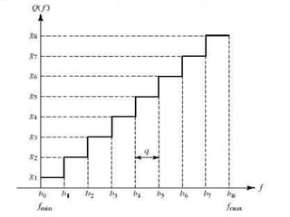
L=2n, then Step size Q = (Fmax – Fmin) / L
Interval i is mapped to the middle value. We will store or
send only index value of quantized value.
An Index value of quantized value Qi (F) = [F – Fmin / Q]
Quantized value Q (F) = Qi (F) Q + Q / 2 + Fmin
But there are some problems raised in uniform
quantization those are
Only optimal for uniformly distributed signal.
Real audio signals are more concentrated near zeros.
The Human ear is more sensitive to quantization errors at
small values.
The solution for this problem is using Non- uniform
quantization. In this Process quantization interval is
smaller near zero.
13. The encoder encodes the quantized samples. Each
quantized sample is encoded into an 8-bit code word by
using A-law in the encoding process.
Bit 1 is the most significant bit (MSB), it represents the
polarity of the sample. “1” represents positive polarity and
“0” represents negative polarity.
Bit 2,3 and 4 will defines the location of sample value.
These three bits together form linear curve for low level
negative or positive samples.
Bit 5,6,7 and 8 are the least significant bits (LSB) it
represents one of the segments quantized value. Each
segment is divided into 16 quantum levels.
14. PCM is two types Differential Pulse Code
Modulation (DPCM) and Adaptive Differential Pulse
Code Modulation (ADPCM).
In DPCM only the difference between a sample and
the previous value is encoded. The difference will be
much smaller than the total sample value so we need
some bits for getting same accuracy as in ordinary
PCM. So that the required bit rate will also reduce.
For example, in 5 bit code 1 bit is for polarity and the
remaining 4 bits for 16 quantum levels.
15. ADPCM is achieved by adapting the quantizing
levels to analog signal characteristics. We can
estimate the values with preceding sample values.
Error estimation is done as same as in DPCM. In
32Kbps ADPCM method difference between
predicted value and sample value is coded with 4
bits, so that we’ll get 15 quantum levels. In this
method data rate is half of the conventional PCM.
16. Pulse Code Demodulation will be doing the
same modulation process in reverse. Demodulation
starts with decoding process, during transmission
the PCM signal will effected by the noise
interference. So, before the PCM signal sends into
the PCM demodulator, we have to recover the signal
into the original level for that we are using a
comparator. The PCM signal is a series pulse wave
signal, but for demodulation we need wave to be
parallel.
17. By using a serial to parallel converter the series pulse
wave signal will be converted into a parallel digital
signal. After that the signal will pass through n-bits
decoder, it should be a Digital to Analog converter.
Decoder recovers the original quantization values of
the digital signal. This quantization value also
includes a lot of high frequency harmonics with
original audio signals. For avoiding unnecessary
signals we utilize a low-pass filter at the final part.
18. Analog signal can be transmitted over a high- speed
digital communication system.
Probability of occurring error will reduce by the use of
appropriate coding methods.
PCM is used in Telkom system, digital audio recording,
digitized video special effects, digital video, voice mail.
PCM is also used in Radio control units as transmitter
and also receiver for remote controlled cars, boats,
planes.
The PCM signal is more resistant to interference than
normal signal.