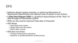
A Data Flow Diagram (DFD) is a graphical representation of the flow of data through a system. It shows the input and output data to the system, where data is stored, and how data is processed. DFDs do not show the timing or sequence of data processing. There are several elements to a DFD including processes, data stores, entities, and data flows. Processes transform input data into output data. Data stores represent where data is stored. Entities are sources or destinations of data outside the system. Data flows show the direction of data movement. DFDs can be physical or logical and have different levels of abstraction.


![Elements of Data Flow Diagrams
• Process – functions of a system to transform input data into output
data. (How data is processed)
• Represented by “circle”.
[name]
Process
www.mbedlabs.com 3](https://image.slidesharecdn.com/dataflowdiagramsmbedlabs-170324022007/85/Data-flow-diagrams-DFD-3-320.jpg)
![Elements of Data Flow Diagrams
• Data Store – Where data is stored. E.g Files, Database.
[Name]
Data Store
www.mbedlabs.com 4](https://image.slidesharecdn.com/dataflowdiagramsmbedlabs-170324022007/85/Data-flow-diagrams-DFD-4-320.jpg)
![Elements of Data Flow Diagrams
• Entity – source and destination of data to/from the system.
• Represented by “Rectangle”
• Source – Entity that supplies data to the system.
• Sink – Entity that receives data from the system.
[name]
Entity
Source Sink
www.mbedlabs.com 5](https://image.slidesharecdn.com/dataflowdiagramsmbedlabs-170324022007/85/Data-flow-diagrams-DFD-5-320.jpg)
![Elements of Data Flow Diagrams
• Data Flow – represent data flow along with direction of flow
(source/sink).
[Name]
Data Flow
www.mbedlabs.com 6](https://image.slidesharecdn.com/dataflowdiagramsmbedlabs-170324022007/85/Data-flow-diagrams-DFD-6-320.jpg)


![제 23회 보아즈(BOAZ) 빅데이터 컨퍼런스 - [MBOAX] : ABSA를 활용한 소비자 반응 분석 기반 운영 효율화 대시보드 설계](https://cdn.slidesharecdn.com/ss_thumbnails/3-1boaz23rdconferencemboax-260203102709-9d519923-thumbnail.jpg?width=640&height=640&fit=bounds)


