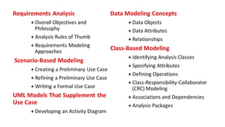
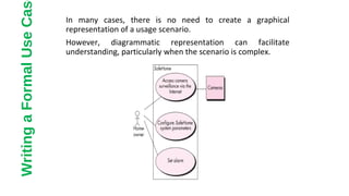
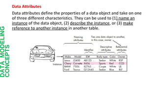
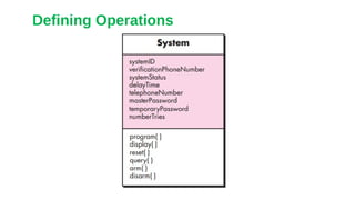
This document discusses different approaches to requirements modeling including scenario-based modeling using use cases and activity diagrams, data modeling using entity-relationship diagrams, and class-based modeling using class-responsibility-collaborator diagrams. Requirements modeling depicts requirements using text and diagrams to help validate requirements from different perspectives and uncover errors, inconsistencies, and omissions. The models focus on what the system needs to do at a high level rather than implementation details.
![Budd [Bud96] suggests a taxonomy of classes that includes producers
(sources) and consumers(sinks) of data, data managers, viewor observer
classes, and helper classes.
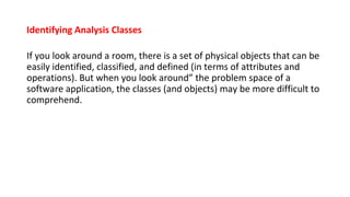
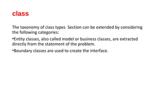
Another important categorization, defining entity, boundary, and
controller classes,](https://image.slidesharecdn.com/thefinal2003-140325052833-phpapp01/85/CHAPTER-6-REQUIREMENTS-MODELING-SCENARIO-based-Model-Class-based-moddel-29-320.jpg)
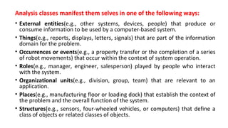
![Coad and Yourdon [Coa91] suggest six
selection characteristics that should be used
as you consider each potential class for
inclusion in the analysis model:
• Retained information.
• Needed services.
• Multiple attributes.
• Common attributes.
• Common operations
• Essential requirements.](https://image.slidesharecdn.com/thefinal2003-140325052833-phpapp01/85/CHAPTER-6-REQUIREMENTS-MODELING-SCENARIO-based-Model-Class-based-moddel-30-320.jpg)
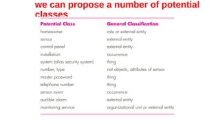
![Responsibilities.
Basic guidelines for identifying responsibilities (attributes and
operations) have been presented in Sections 6.5.2 and 6.5.3. Wirfs-
Brock and her colleagues [Wir90] suggest five guidelines for allocating
responsibilities to classes:
•System intelligence should be distributed across classes to best
address the needs of the problem.
•Each responsibility should be stated as generally as possible.](https://image.slidesharecdn.com/thefinal2003-140325052833-phpapp01/85/CHAPTER-6-REQUIREMENTS-MODELING-SCENARIO-based-Model-Class-based-moddel-36-320.jpg)