Download to read offline
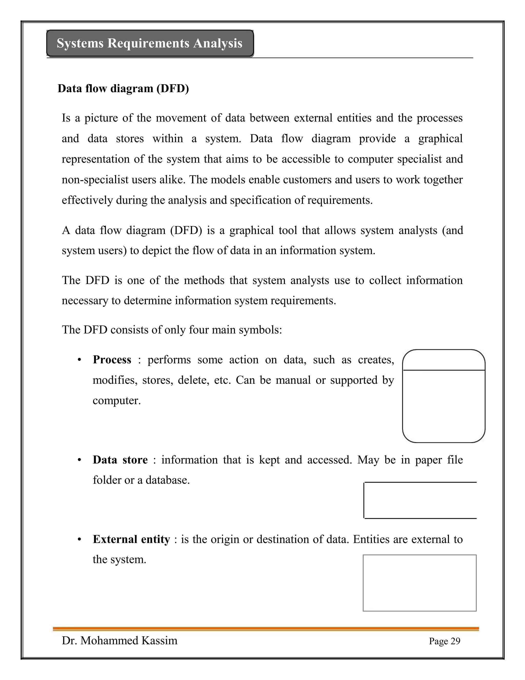
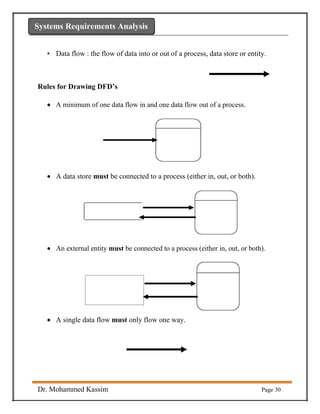
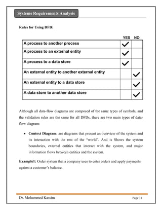
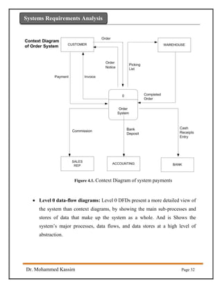
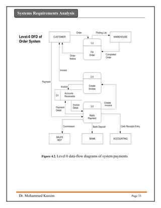


Data flow diagrams (DFDs) provide a graphical representation of how data moves through a system. DFDs use four main symbols: processes, data stores, external entities, and data flows. They allow system analysts and users to depict and understand the flow of data in a system. DFDs come in two main types: context diagrams provide an overview of the system and its interactions, while level 0 DFDs show more detail about the system's major sub-processes, data stores, and flows at a high level. Together, DFDs enable customers and users to specify requirements by modeling the system's data flows.