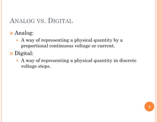
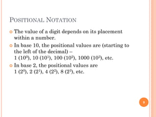
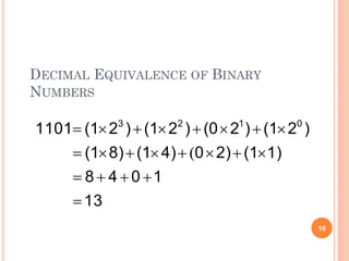
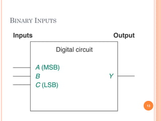
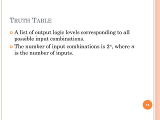
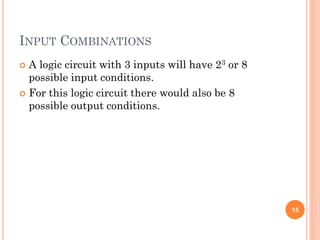
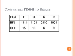
This document provides an overview of digital systems fundamentals, including:
- Analog signals have continuous values while digital signals can only have discrete values (0 or 1).
- Digital electronics uses binary logic levels to represent information, with a high voltage representing 1 and a low voltage representing 0.
- The binary number system uses positional notation to represent numbers using only the digits 0 and 1.
- Digital circuits operate on binary inputs and outputs, with truth tables listing all possible input-output combinations for a logic gate or circuit.
2. ANALOG VS. DIGITAL
Analog:
A way of representing a physical quantity by a
proportional continuous voltage or current.
Digital:
A way of representing a physical quantity in discrete
voltage steps.
2
3. ANALOG ELECTRONICS
Values are continuously variable between defined
values.
Can have any value within a defined range.
3
6. DIGITAL LOGIC LEVELS
Logic HIGH is the higher voltage and
represented by binary digit ‘1’.
Logic LOW is the lower voltage and represented
by binary digit ‘0’.
6
8. BINARY NUMBER SYSTEM
Uses two digits, 0 and 1.
Represents any number using the positional
notation.
8
9. POSITIONAL NOTATION
The value of a digit depends on its placement
within a number.
In base 10, the positional values are (starting to
the left of the decimal) –
1 (100), 10 (101), 100 (102), 1000 (103), etc.
In base 2, the positional values are
1 (20), 2 (21), 4 (22), 8 (23), etc.
9
11. BIT
Shorthand for binary digit, a logic 0 or 1.
The most significant bit (MSB) is the leftmost bit
of a binary number.
The least significant bit (LSB) is the rightmost
bit of a binary number.
11
12. BINARY INPUTS
Digital circuits operate by accepting logic levels
(0,1) at their input(s).
The corresponding output(s) logic level will
change (0,1).
12
14. TRUTH TABLE
A list of output logic levels corresponding to all
possible input combinations.
The number of input combinations is 2n, where n
is the number of inputs.
14
15. INPUT COMBINATIONS
A logic circuit with 3 inputs will have 23 or 8
possible input conditions.
For this logic circuit there would also be 8
possible output conditions.
15
16. CONSTRUCTING A BINARY SEQUENCE
FOR A TRUTH TABLE – 1
Two methods:
Learn to count in binary
Follow a simple repetitive pattern
Memorize the binary numbers from 0000 to 1111
and their decimal equivalents (0 to 15).
Use the weighted values of binary bits.
16
17. BINARY SEQUENCE FOR A TRUTH TABLE – 1
Logic Level Binary Value Decimal Equivalent
A B C A B C
L L L 0 0 0 0
L L H 0 0 1 1
L H L 0 1 0 2
L H H 0 1 1 3
H L L 1 0 0 4
H L H 1 0 1 5
H H L 1 1 0 6
H H H 1 1 1 7
17
18. FOLLOW A SIMPLE REPETITIVE PATTERN
The LSB of any binary number alternates
between 0 and 1 with every line.
The next bit alternates every two lines.
The next bit alternates every four lines, and so
on.
18
25. SUM POWERS OF 2
Step 1:
Determine the largest power of 2 less than or equal to
the number to be converted.
Place a 1 in that positional location.
25
26. SUM POWERS OF 2
Step 2:
Subtract the number found in Step 1 from the
number to be converted.
For the new number, determine if the next lowest
power of 2 is less than or equal to that number.
26
27. SUM POWERS OF 2
Step 3:
If the new power of two from Step 2 is larger, place a
0 in that positional location.
If the new value is less than or equal, place a 1 in
that positional location.
27
28. SUM POWERS OF 2
Step 4:
Repeat Steps 2 and 3 until there is nothing left to
subtract.
All remaining bits are set to 0.
28
29. REPEATED DIVISION BY 2
Step 1:
Take the number to be converted, and divide it by 2.
The remainder (0 or 1) is the LSB of the binary value.
29
30. REPEATED DIVISION BY 2
Step 2:
Divide the quotient from Step 1 by 2.
The remainder (0 or 1) is the next most significant
bit.
30
31. REPEATED DIVISION BY 2
Step 3:
Continue to execute Step 2 until the quotient is 0.
The last remainder is the MSB.
31
32. FRACTIONAL BINARY NUMBERS
Radix point:
The generalized decimal point. The dividing line
between positive and negative powers for positional
multipliers.
Binary point:
The radix point for binary numbers.
32
33. FRACTIONAL BINARY VALUES
The value immediately to the right of the binary
point is 2–1 = 0.5.
The next value to the right is 2–2 = 0.25.
The next value to the right is 2–4 = 0.125, and so
on.
33
39. COUNTING IN HEXADECIMAL
Values range from 0 to F with the letters A to F
used to represent the values 10 to 15
respectively.
Positional multipliers are powers of 16:
160 = 1, 161 = 16, 162 = 256, etc.
39
40. HEXADECIMAL VS. DECIMAL NUMBERS
40
Decimal
0 1 2 3 4 5 6 7 8 9 10 11 12 13 14 15
Hexadecimal
0 1 2 3 4 5 6 7 8 9 A B C D E F
41. Hex Decimal Binary Hex
(Cont)
Decimal Binary
0 0 0000 8 8 1000
1 1 0001 9 9 1001
2 2 0010 A 10 1010
3 3 0011 B 11 1011
4 4 0100 C 12 1100
5 5 0101 D 13 1101
6 6 0110 E 14 1110
7 7 0111 F 15 1111
41
46. CONVERTING FD69H TO BINARY
46
HEX F D 6 9
BIN 1111 1101 0110 1001
DEC 15 13 6 9
47. PERIODIC DIGITAL WAVEFORMS
A periodic digital waveform is a time-varying
sequence of logic HIGHs and LOWs that repeat
over some period of time.
Period (T) is the time required for the pattern to
repeat.
47
48. PERIODIC DIGITAL WAVEFORMS
Frequency (f) is the number of times per second a
signal repeats and is the reciprocal of period.
f = 1/T
48
52. WAVEFORM DEFINITIONS
Time HIGH (th) is the time a logic signal is in its
HIGH state.
Time LOW (tl) is the time a logic signal is in its
LOW state.
Duty cycle is the ratio of the time a logic signal is
HIGH (th) to the period (T).
52
54. PULSE WAVEFORMS
A pulse is a momentary variation of voltage from
one logic level to the opposite level and back
again.
Amplitude is the voltage magnitude of a pulse.
Edge is the part of a pulse representing the
transition from one logic level to the other.
54
56. PULSE WAVEFORM CHARACTERISTICS
Rising edge is the transition from LOW to HIGH.
Falling edge is the transition from HIGH to
LOW.
Leading edge is the earliest transition.
Falling edge is the latest transition.
56
58. PULSE WAVEFORM TIMING
Pulse width (tw) is the time from the 50% point of
the leading edge to the 50% point of the trailing
edge.
Rise time is the time from 10% to 90% amplitude
of the rising edge.
Fall time is the time from 90% to 10% amplitude
of the falling edge.
58