Download as PDF, PPTX
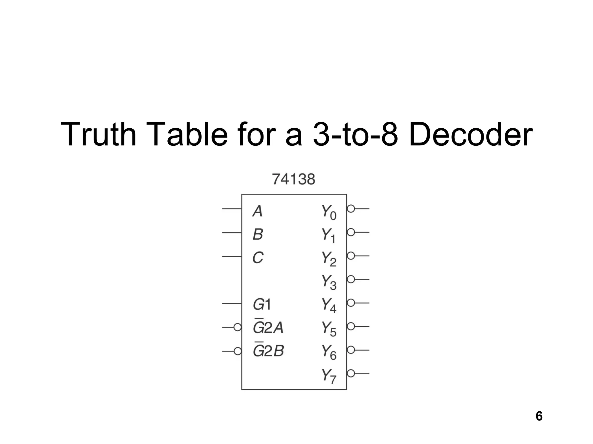
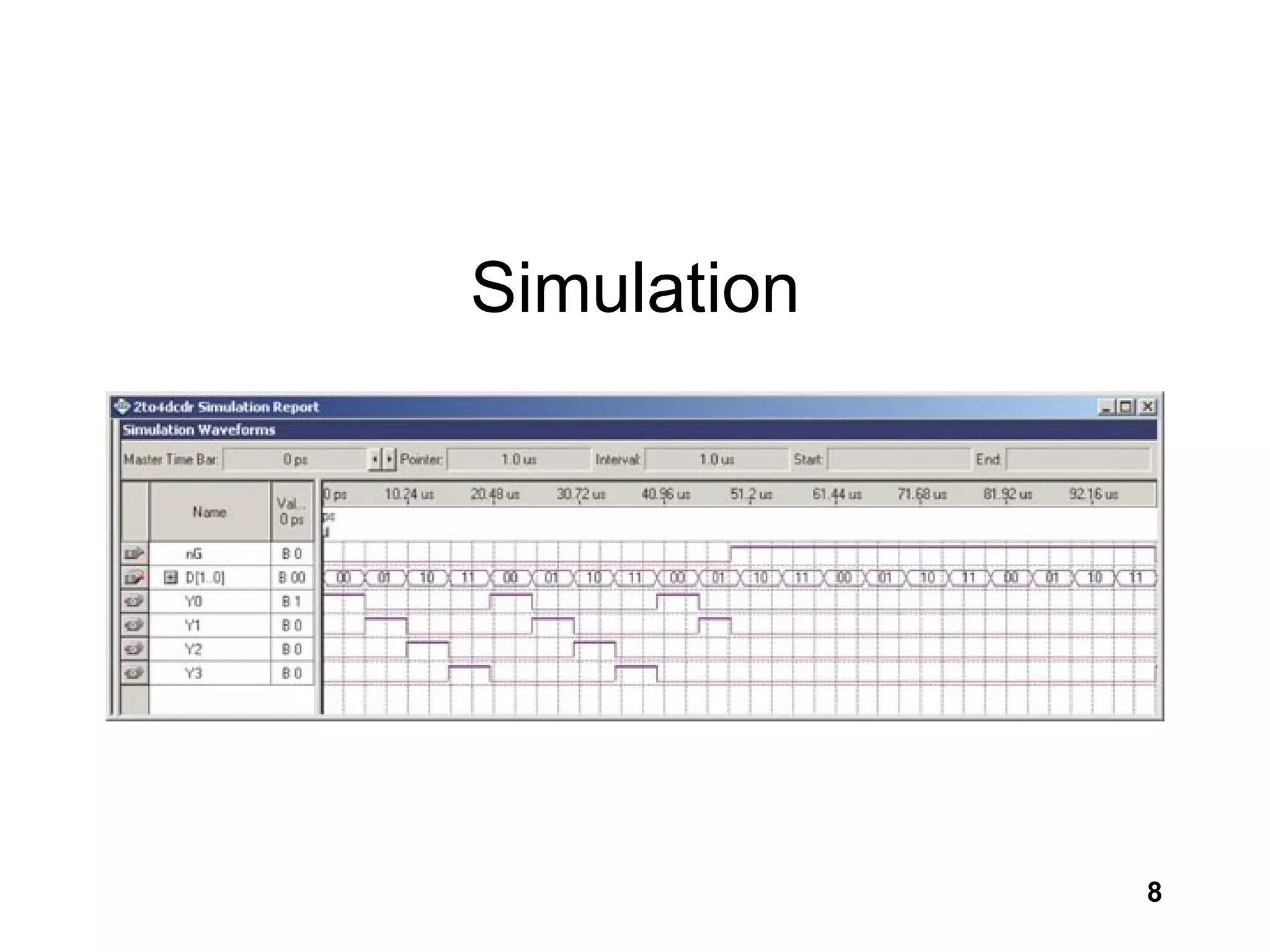
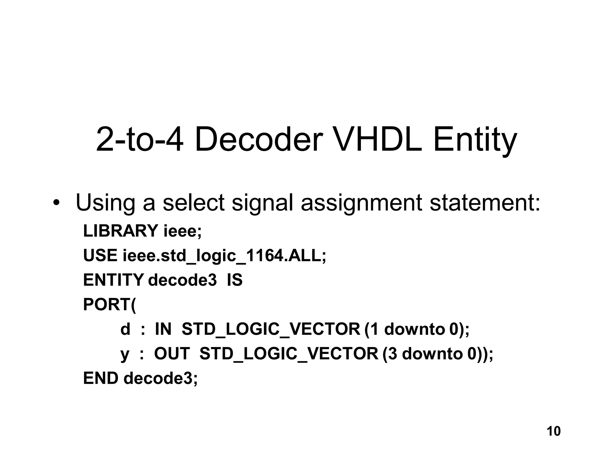
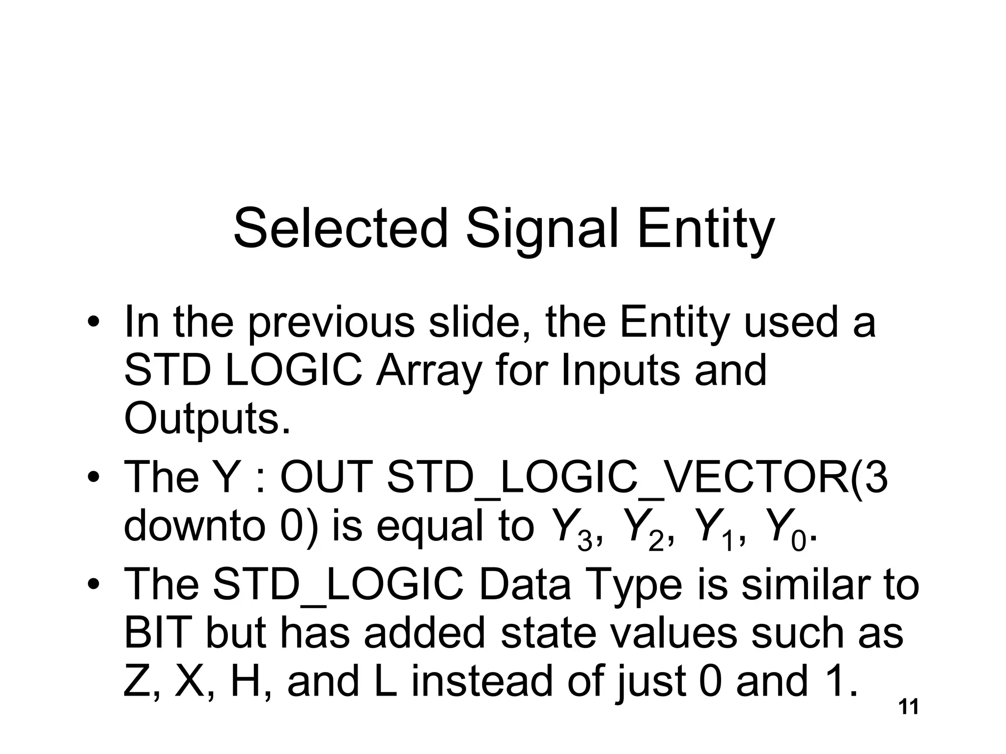
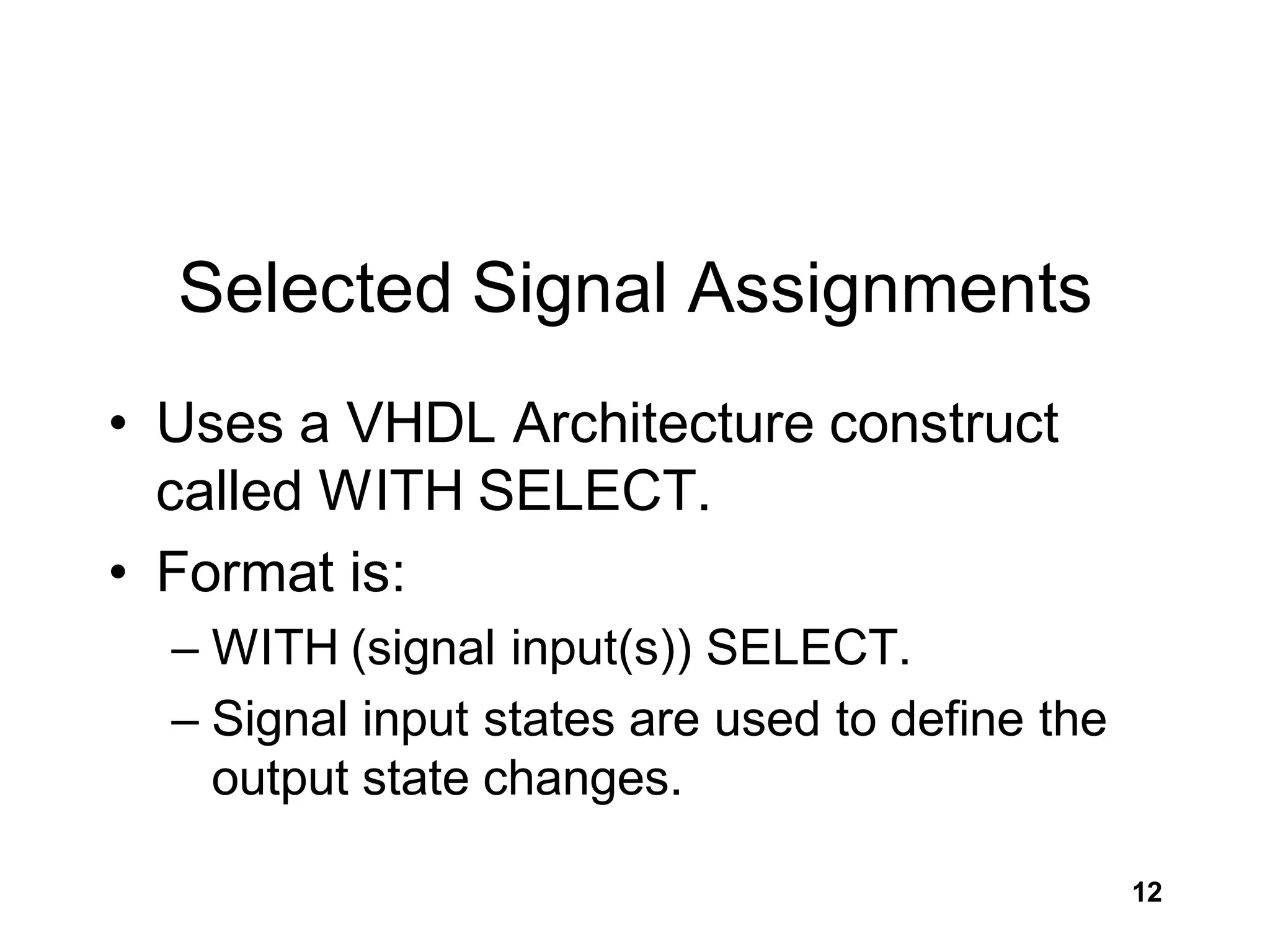
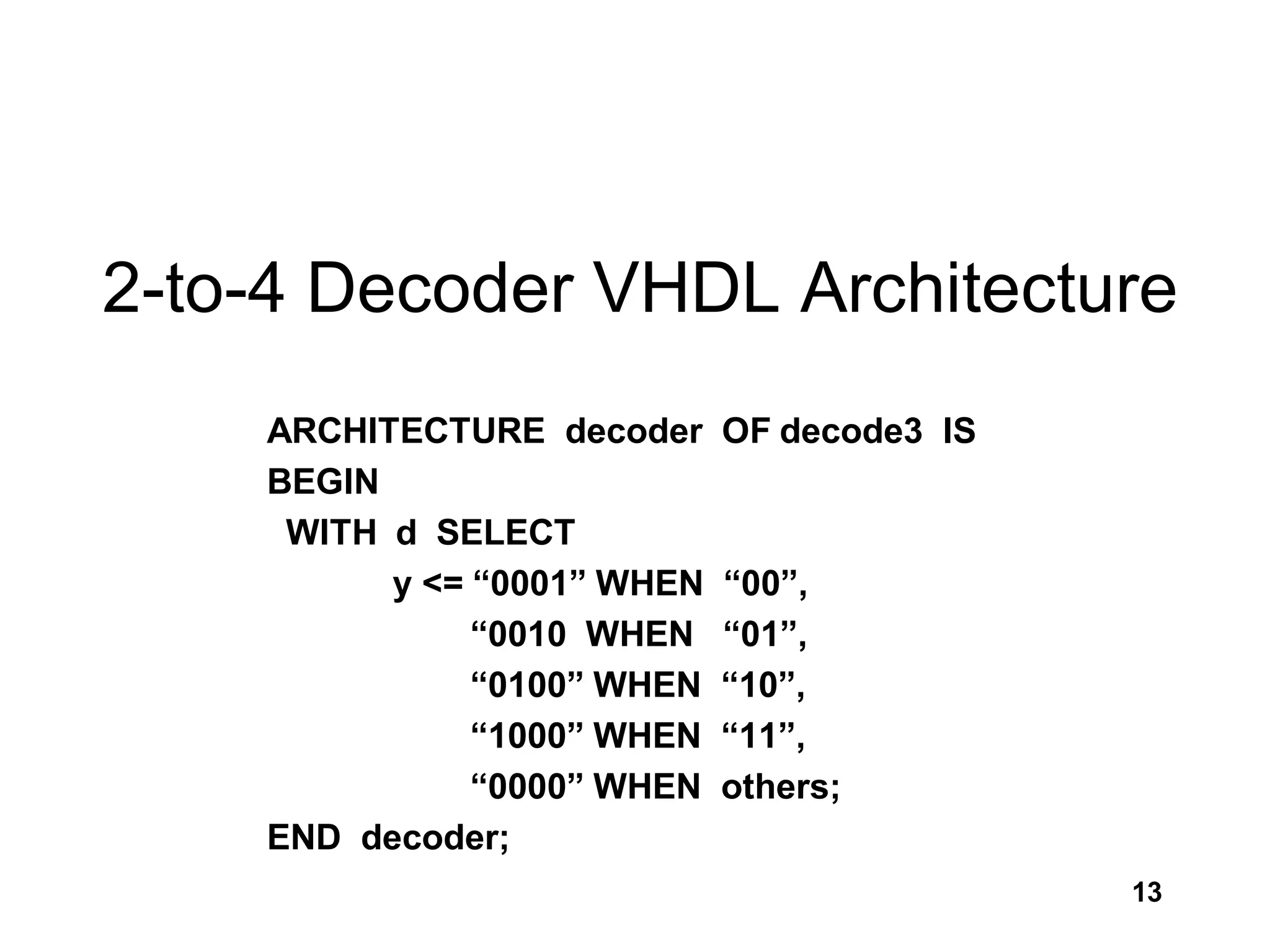
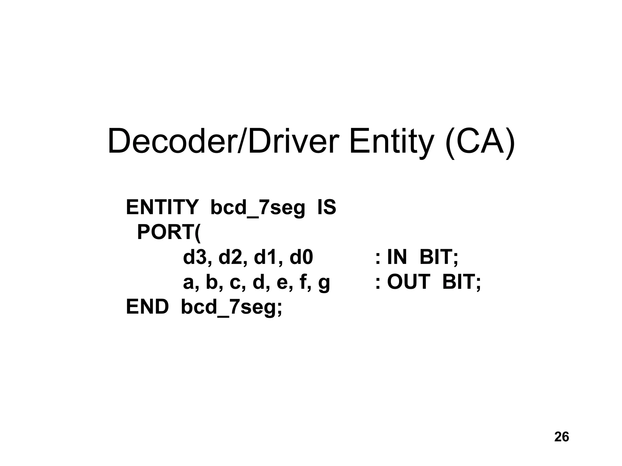
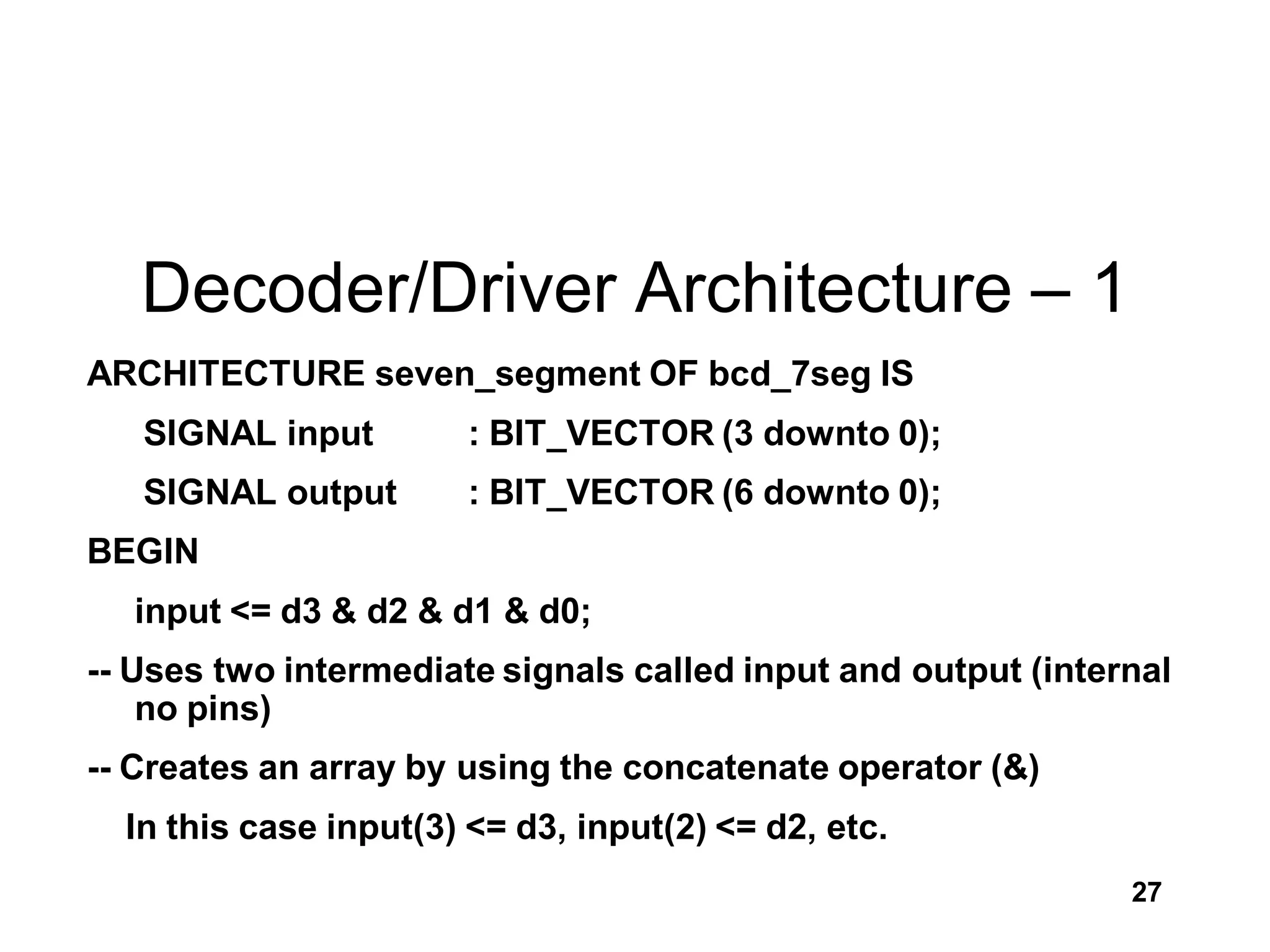
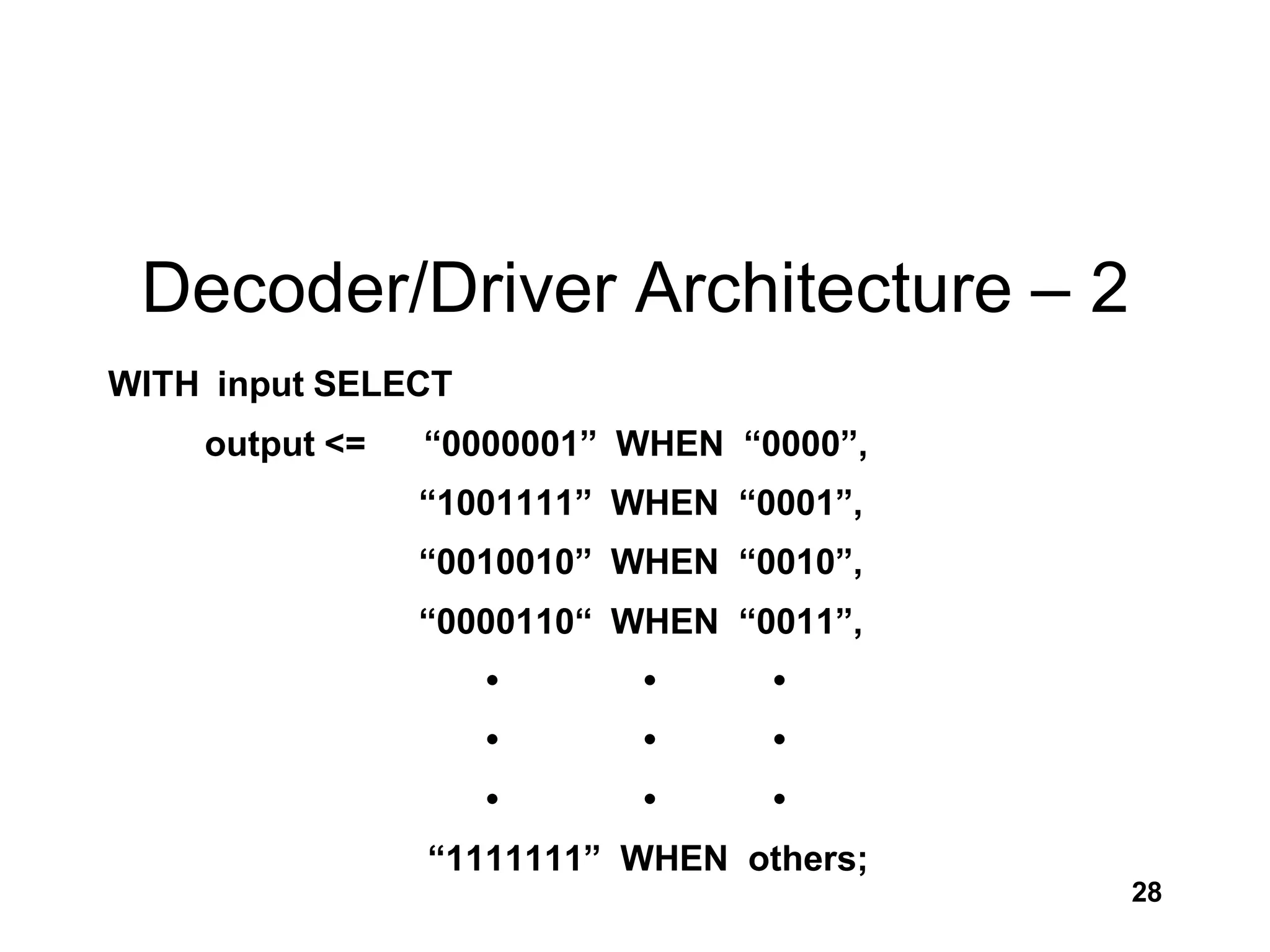
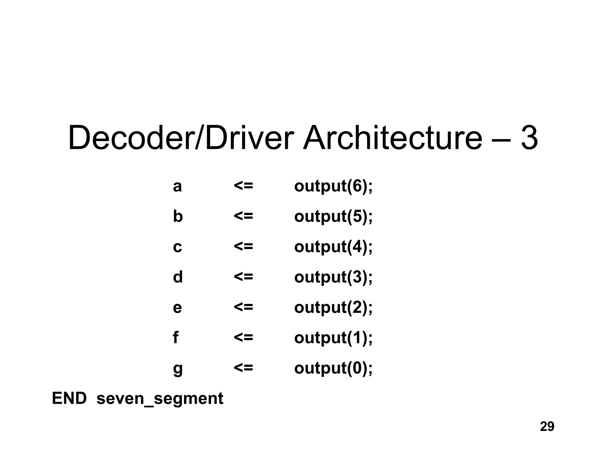
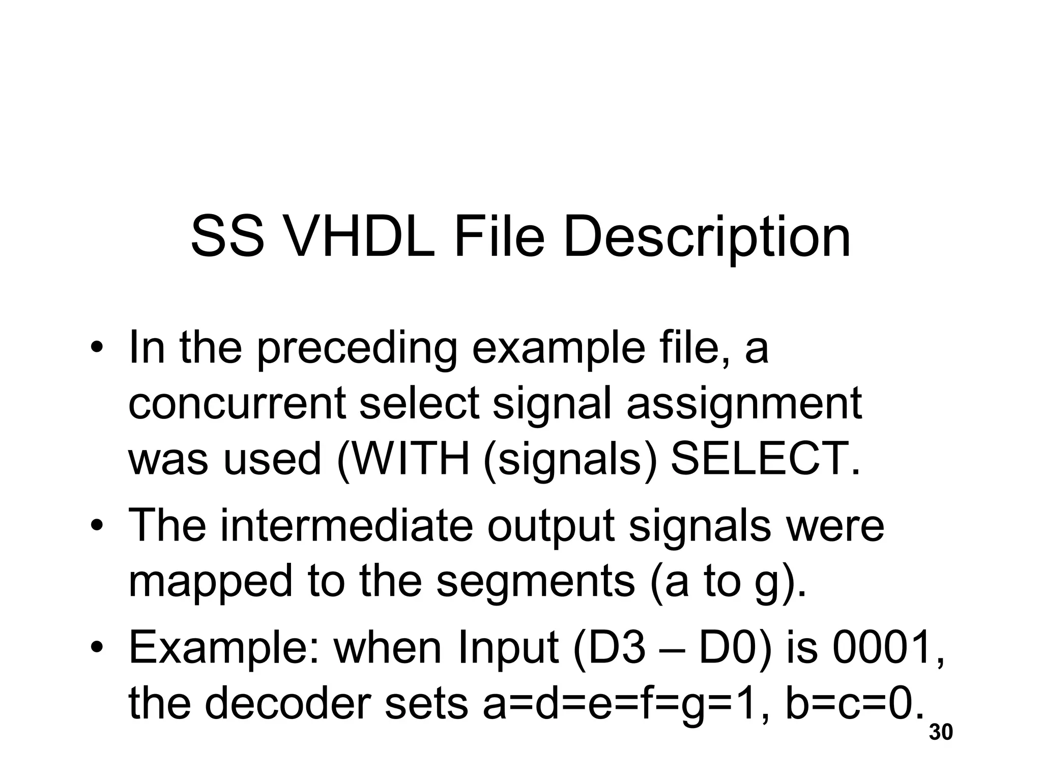
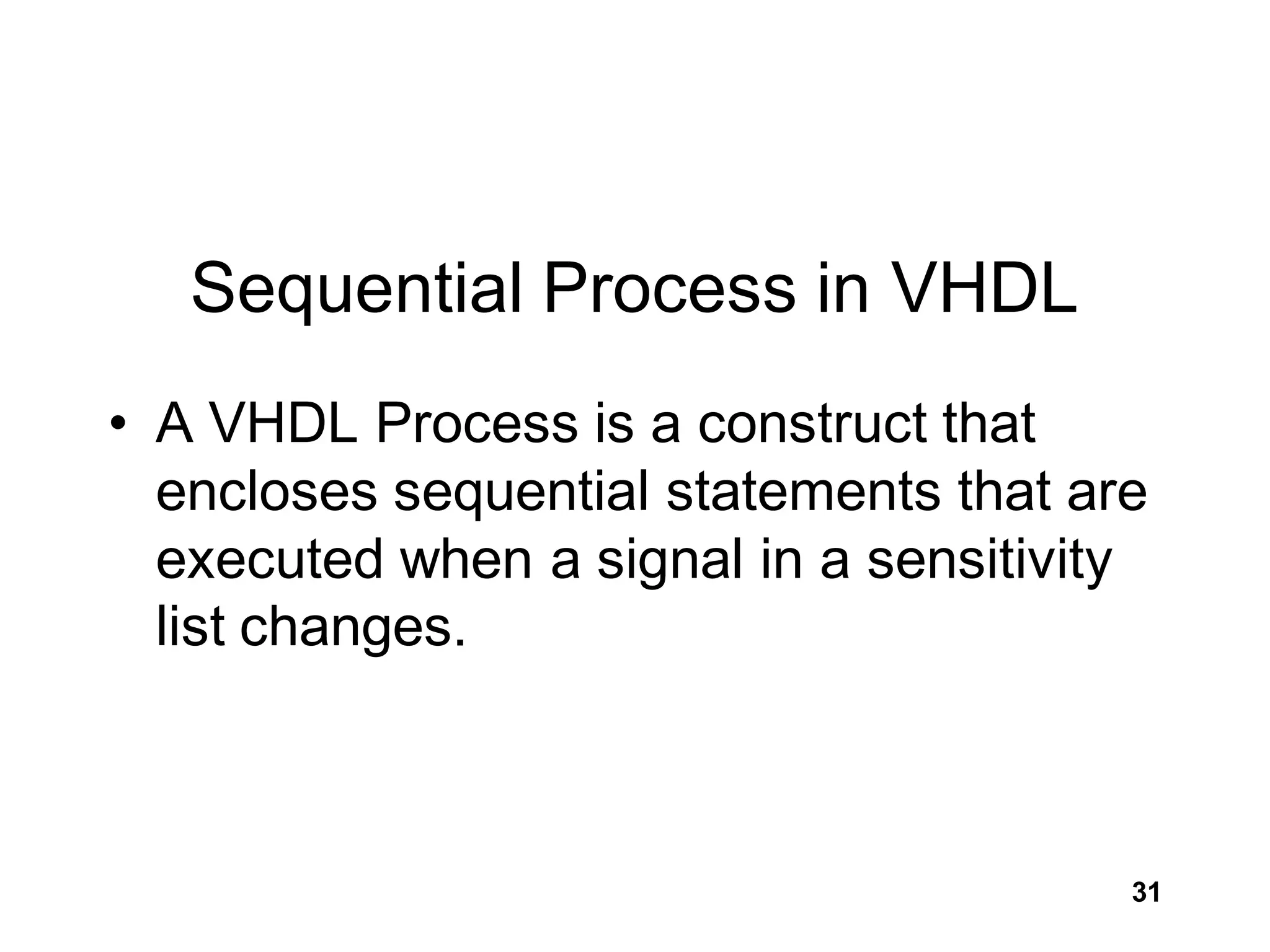
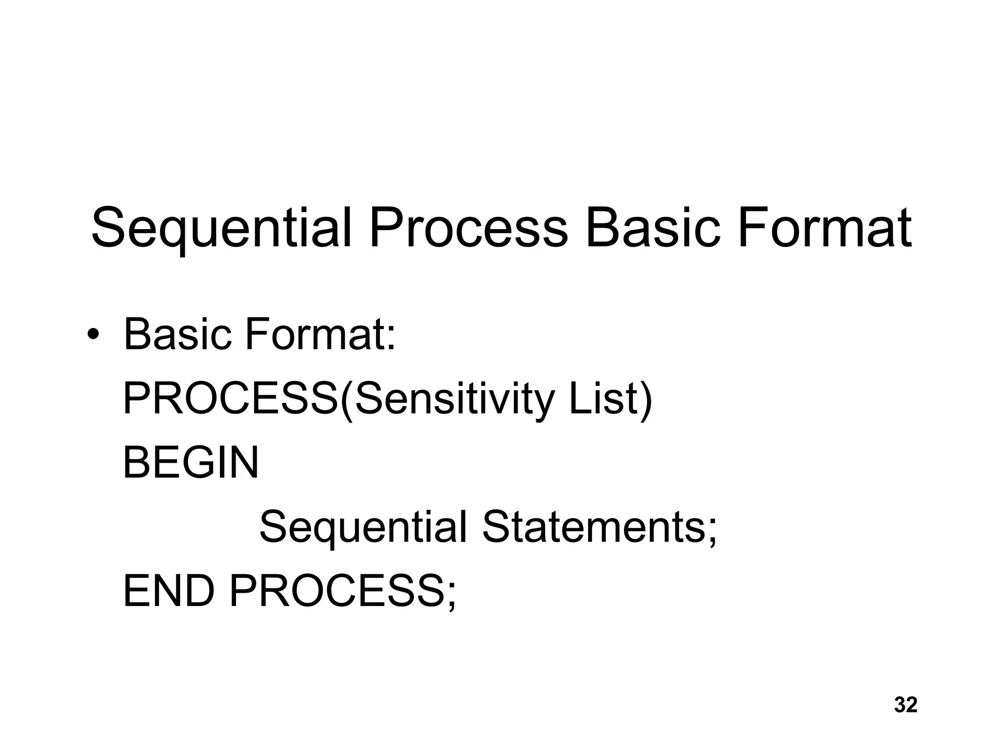
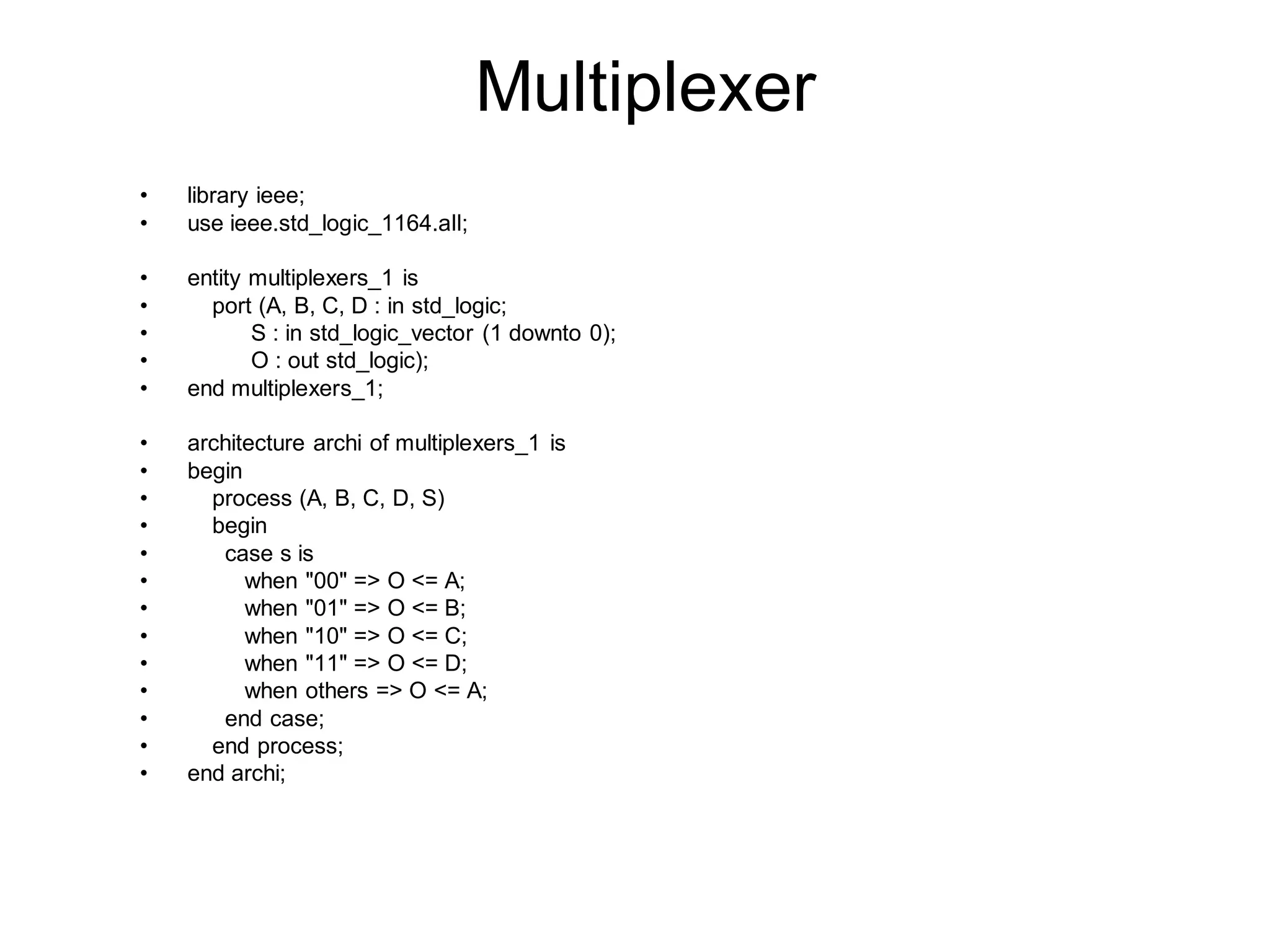
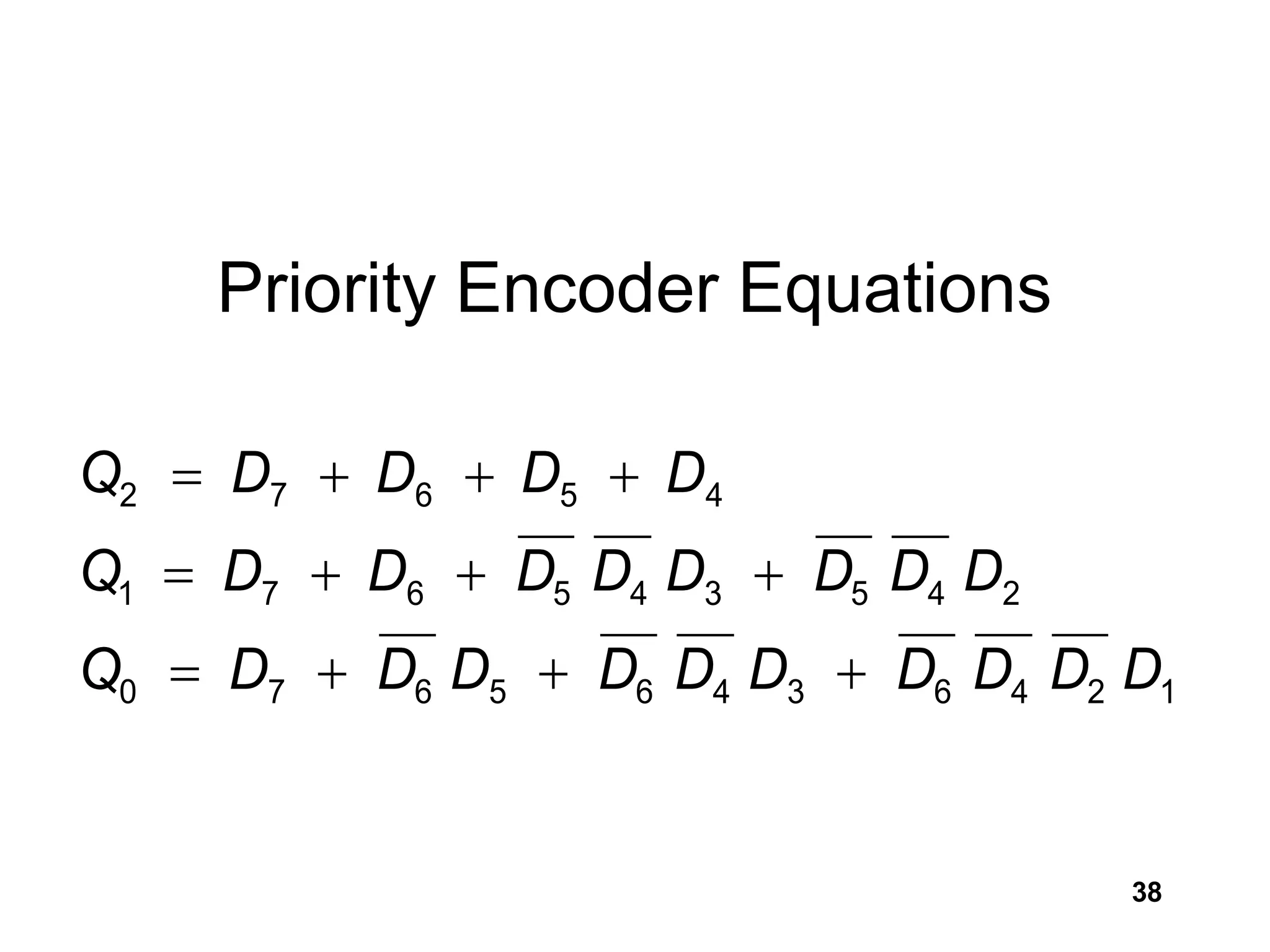
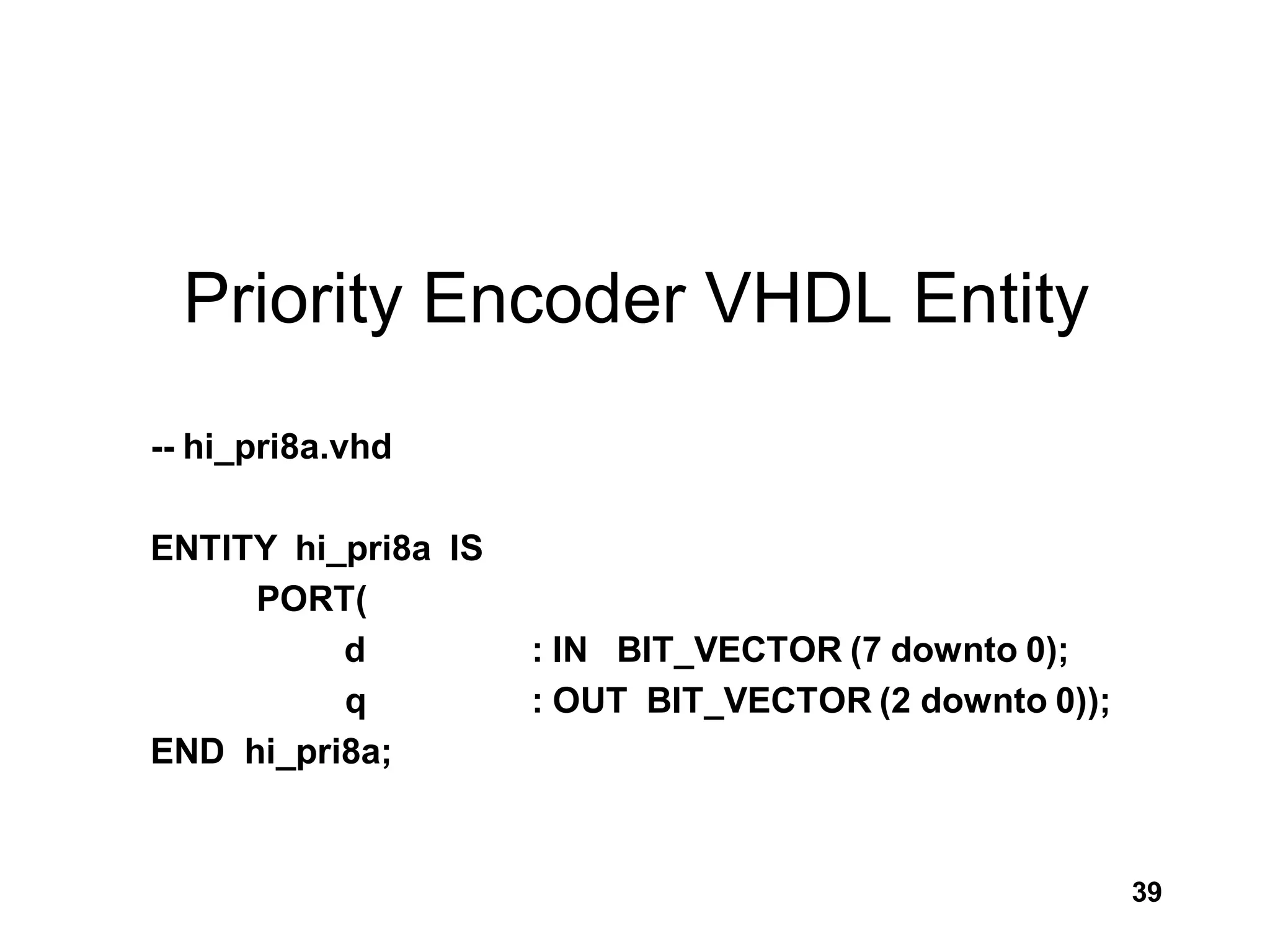
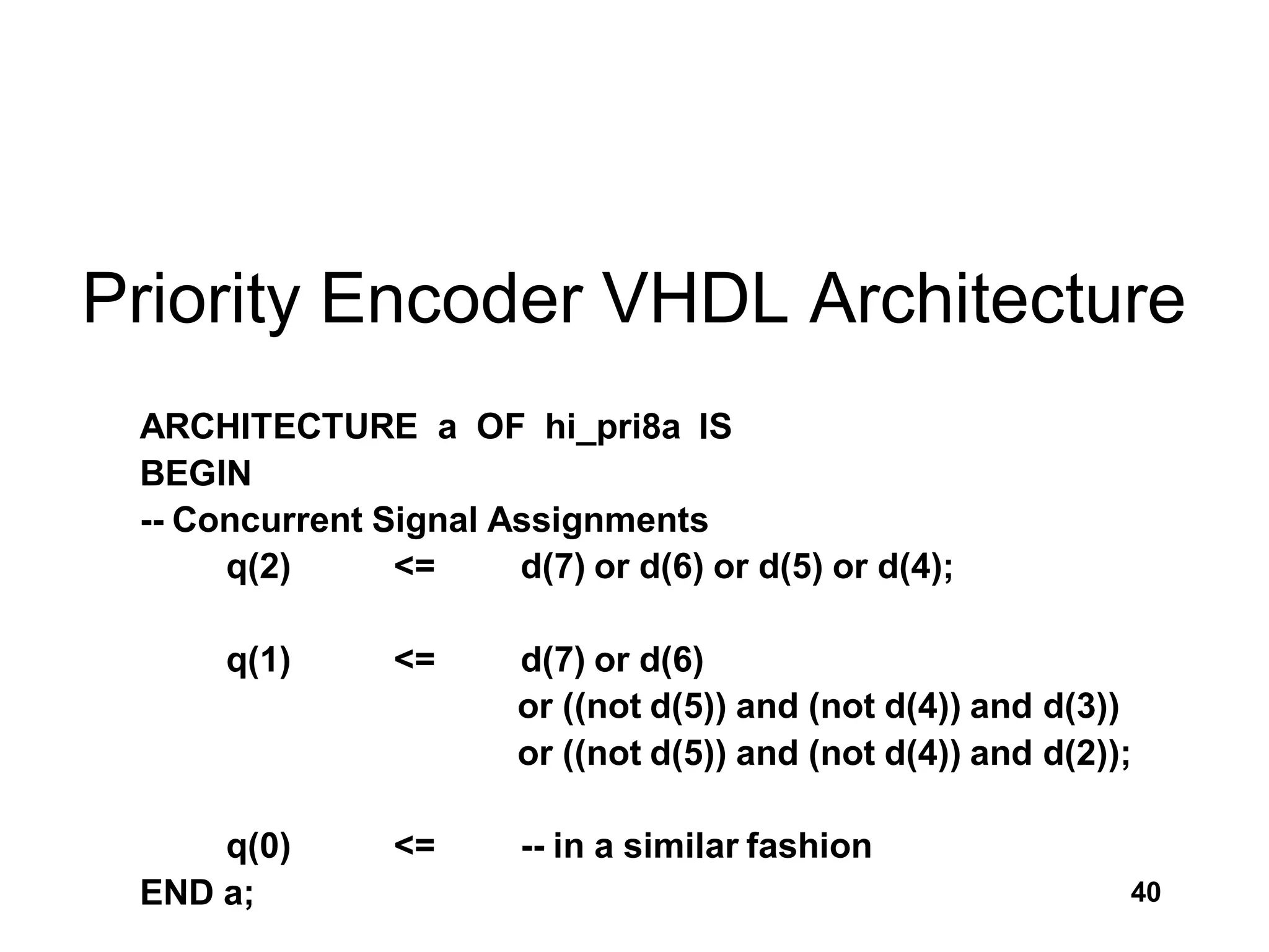
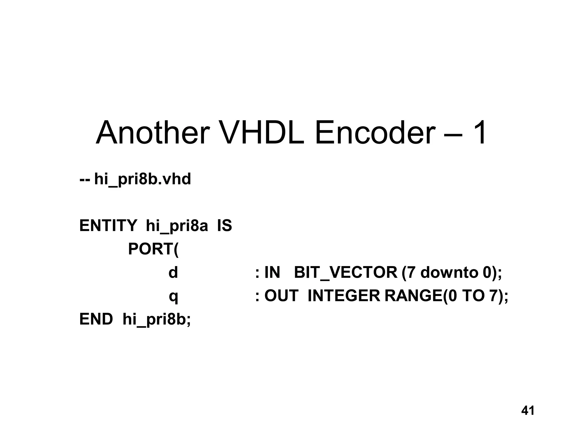
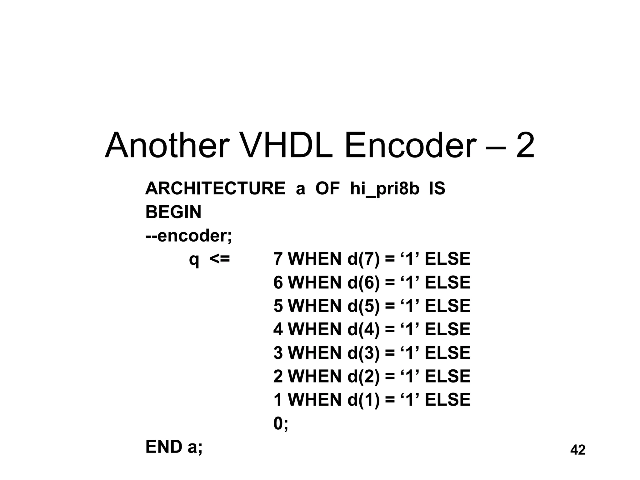
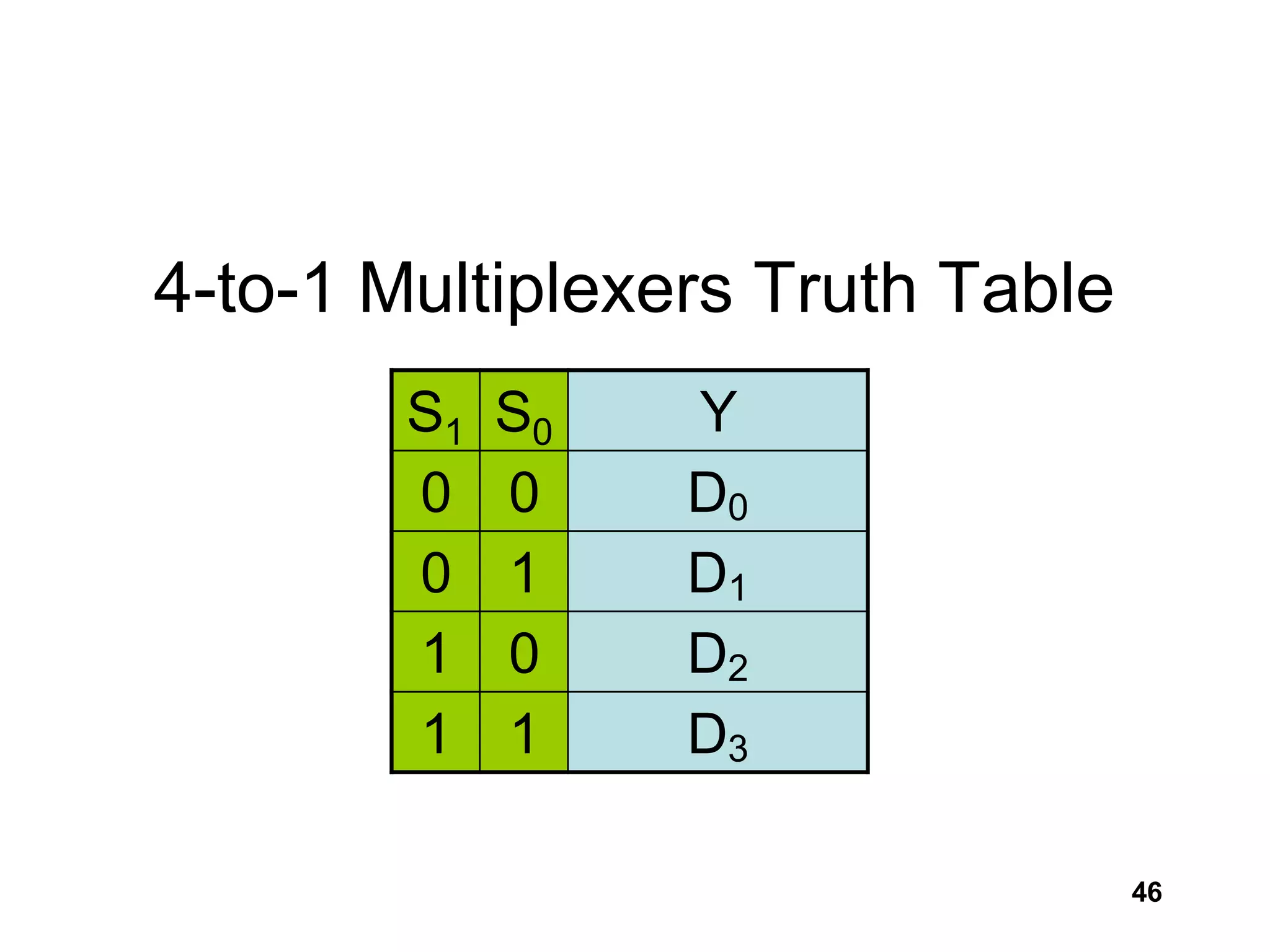
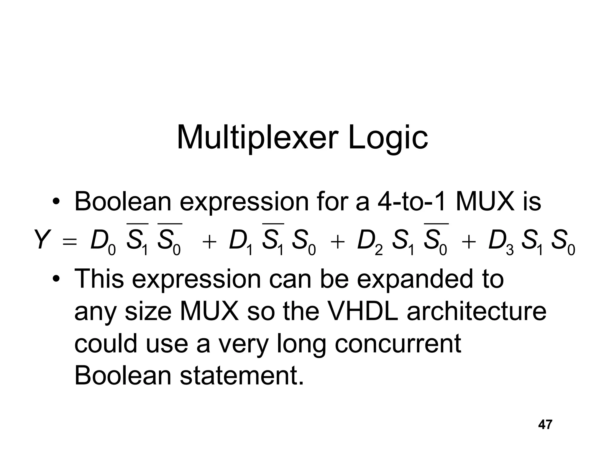
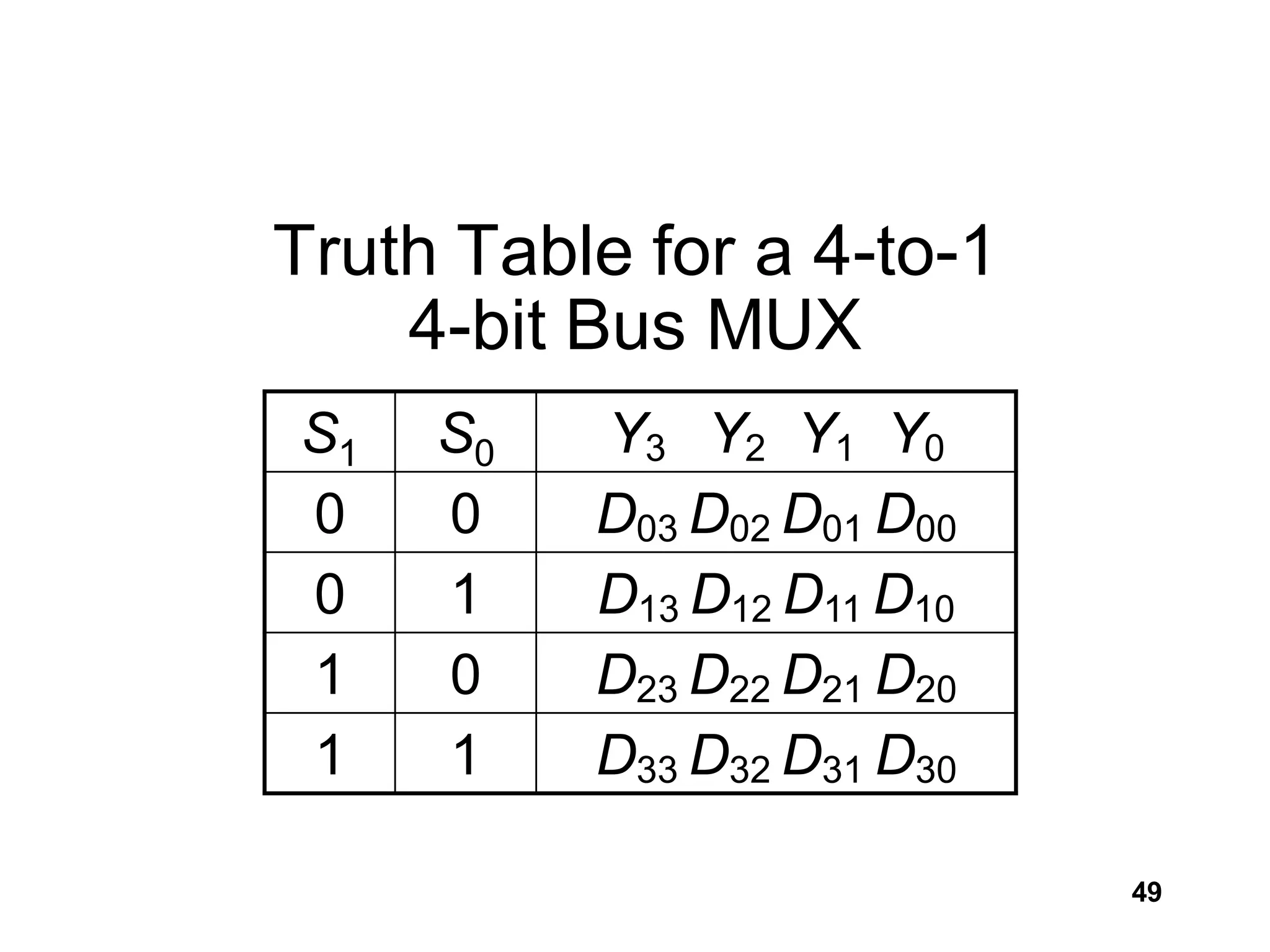
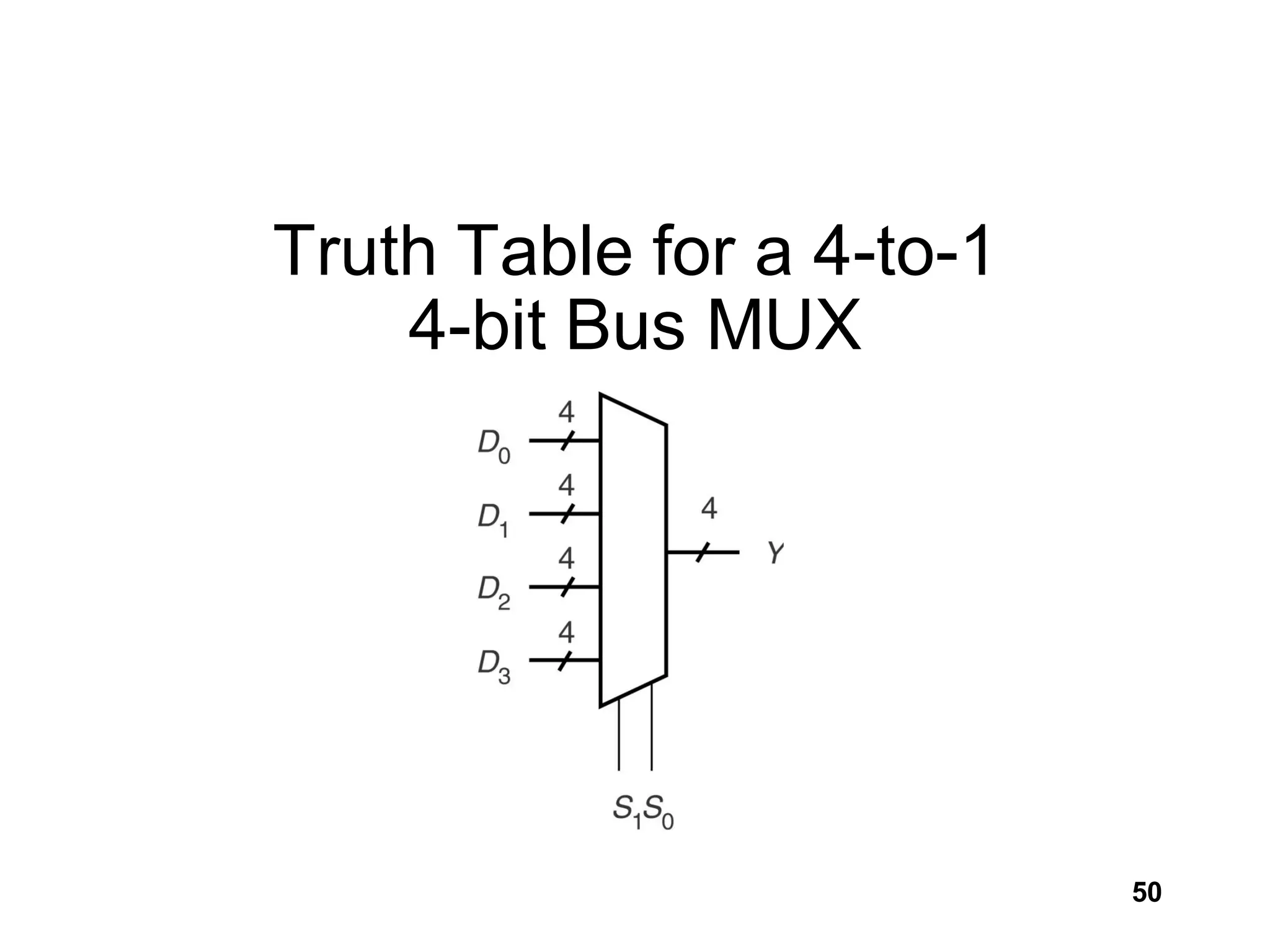
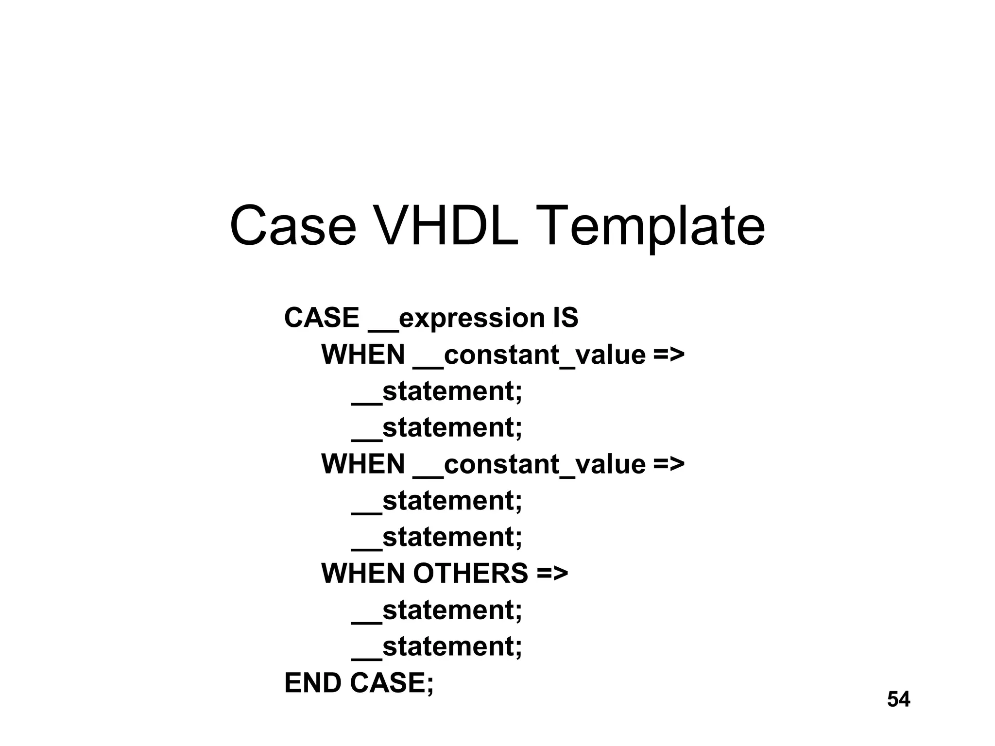
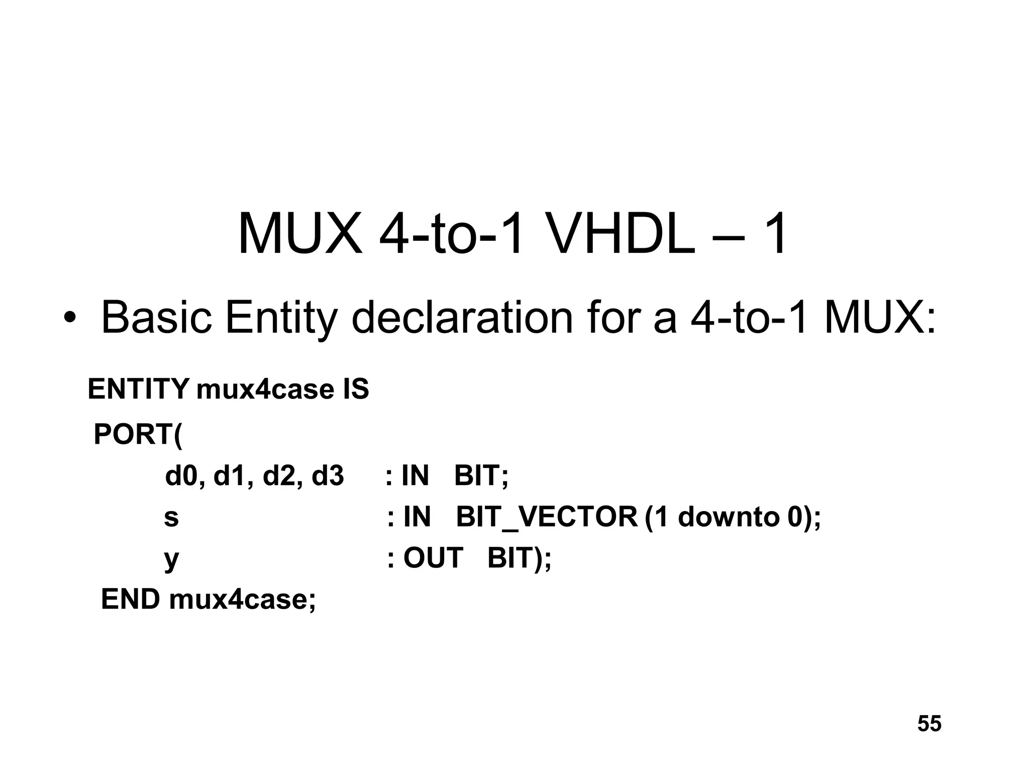
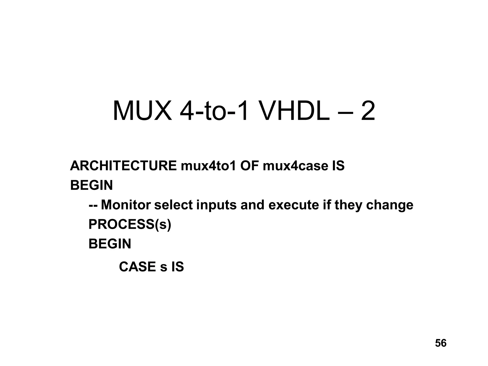
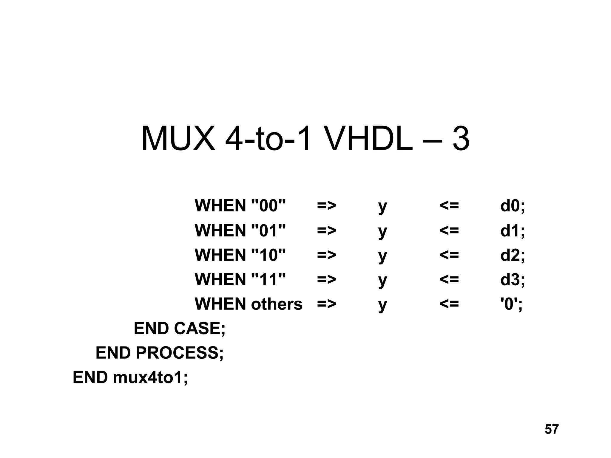
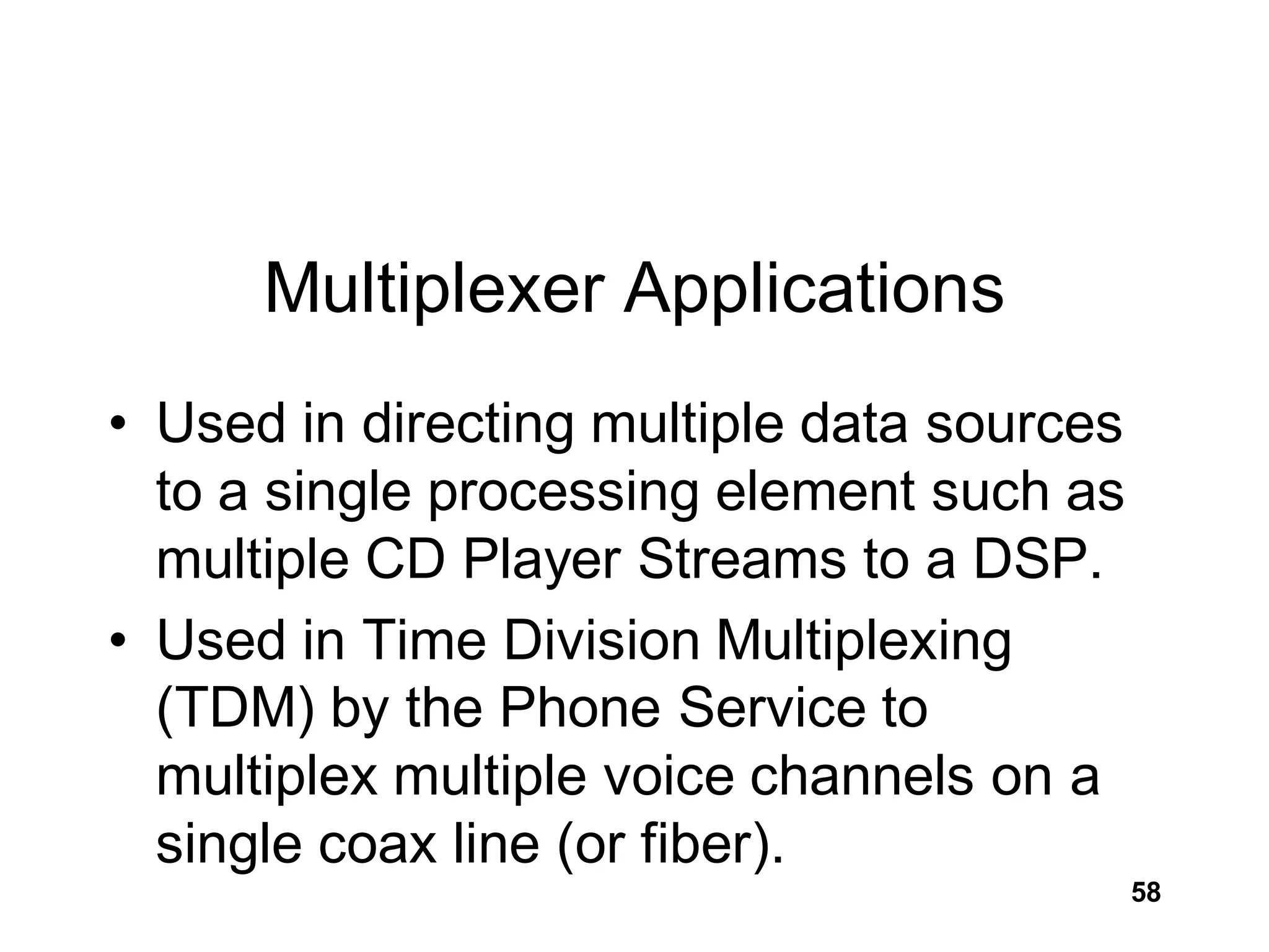
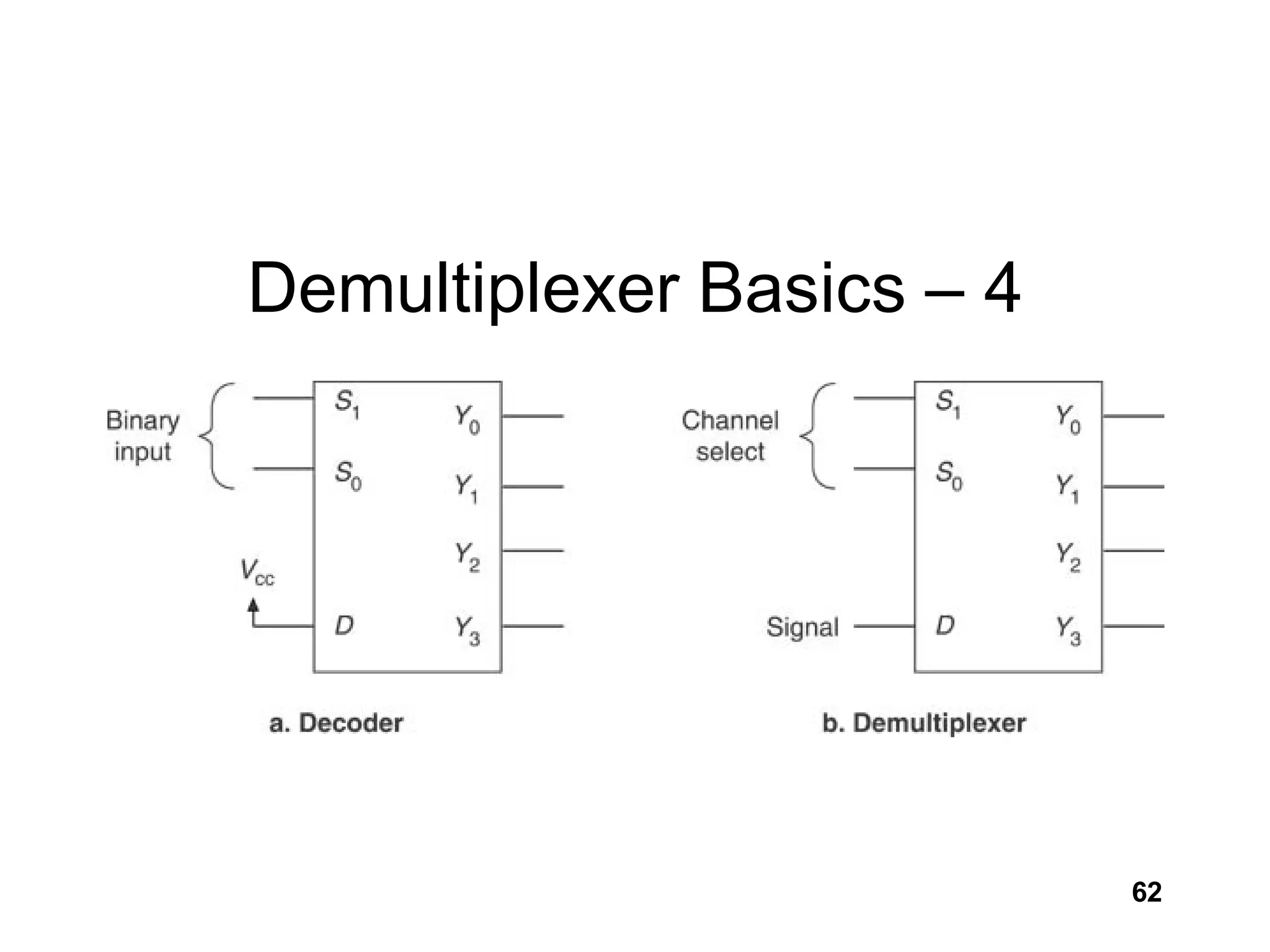
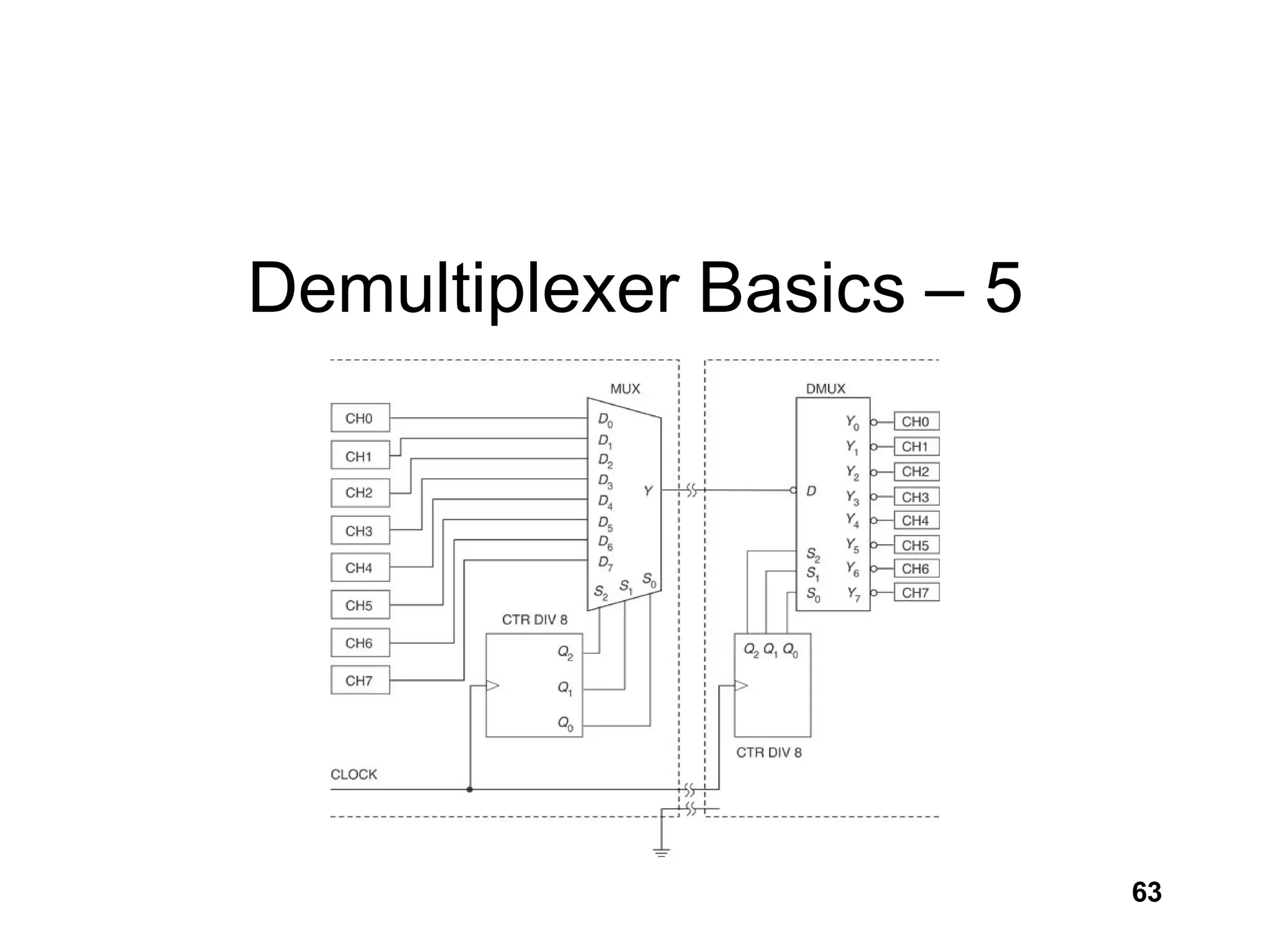
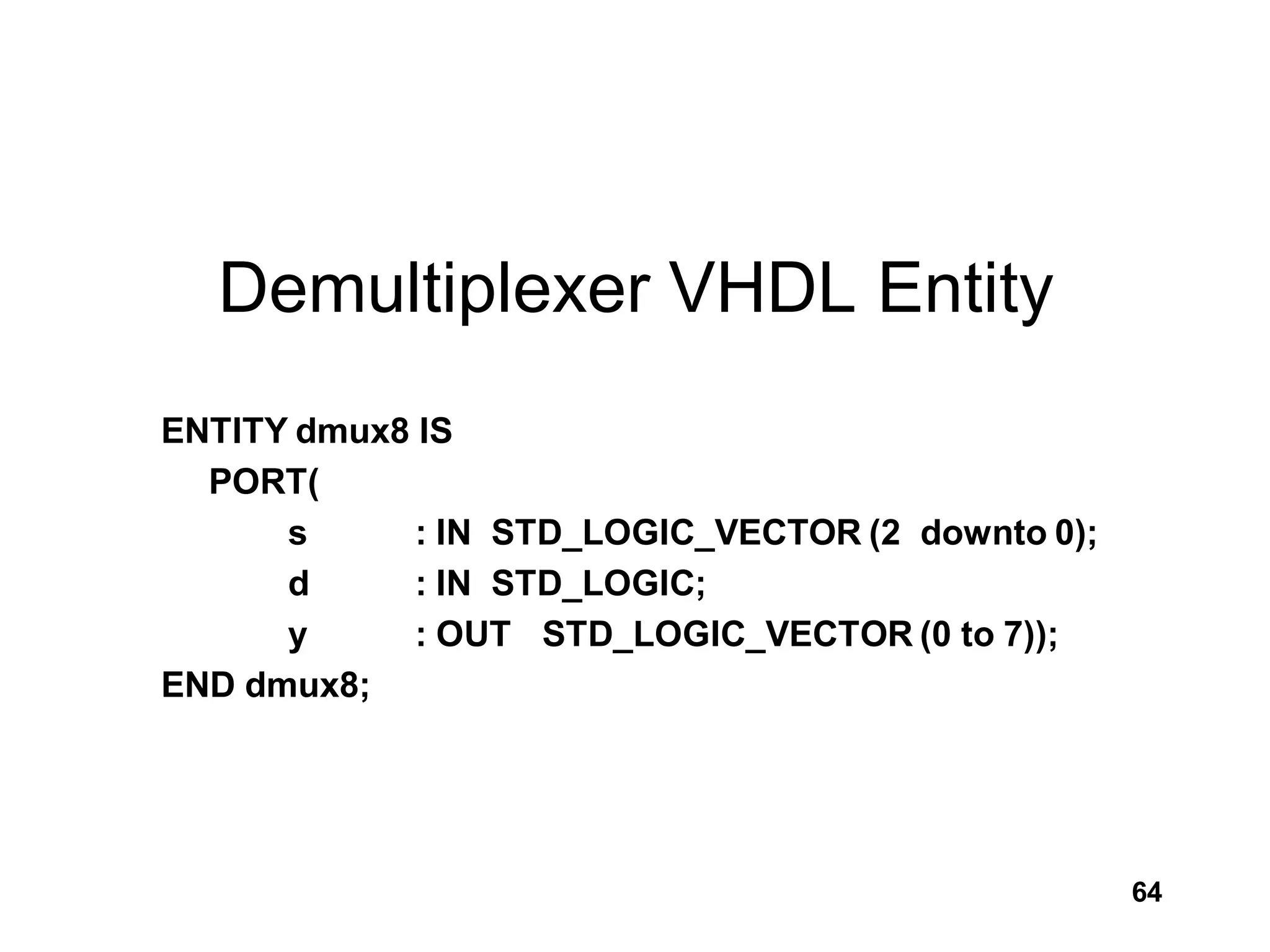
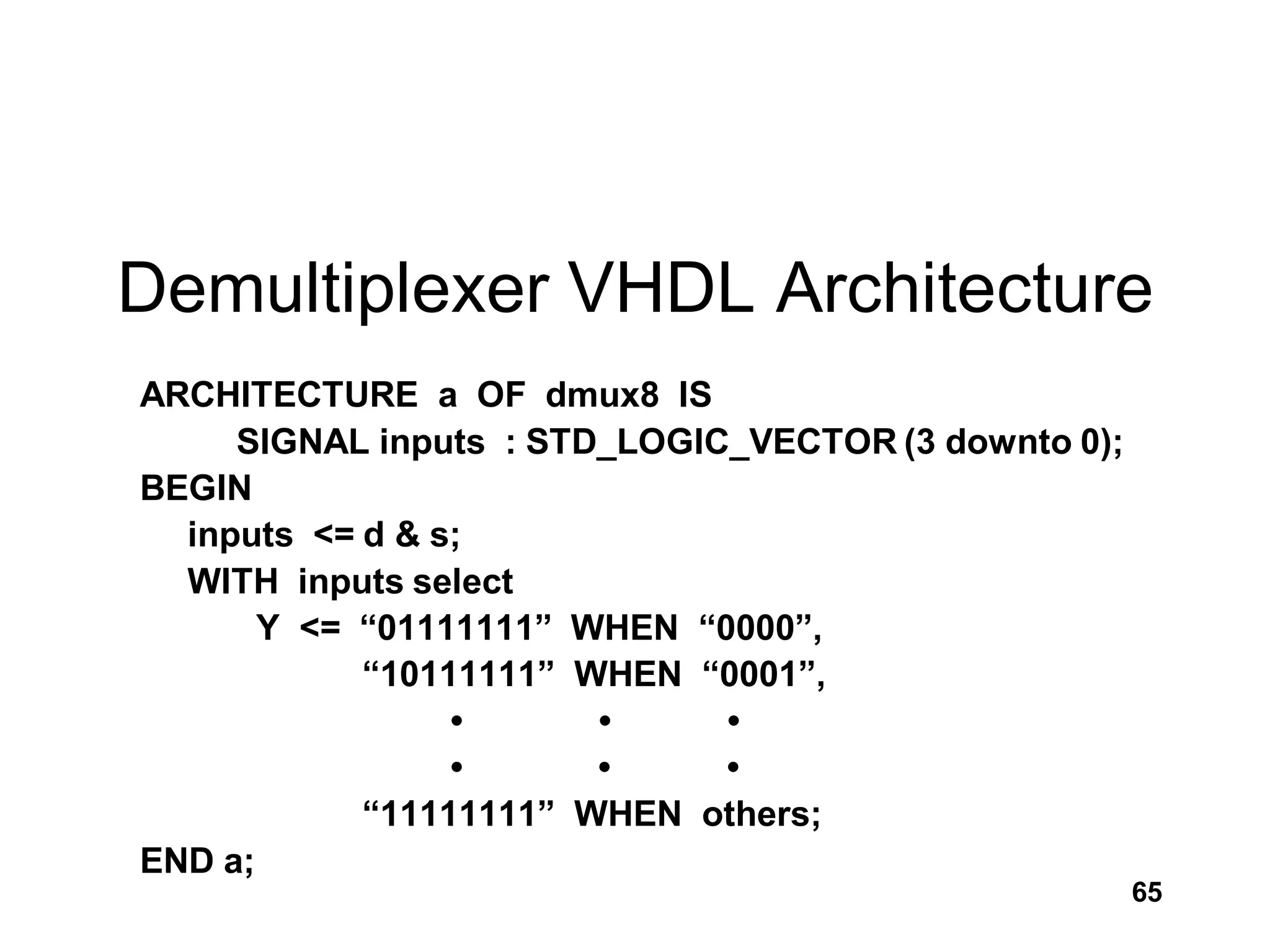
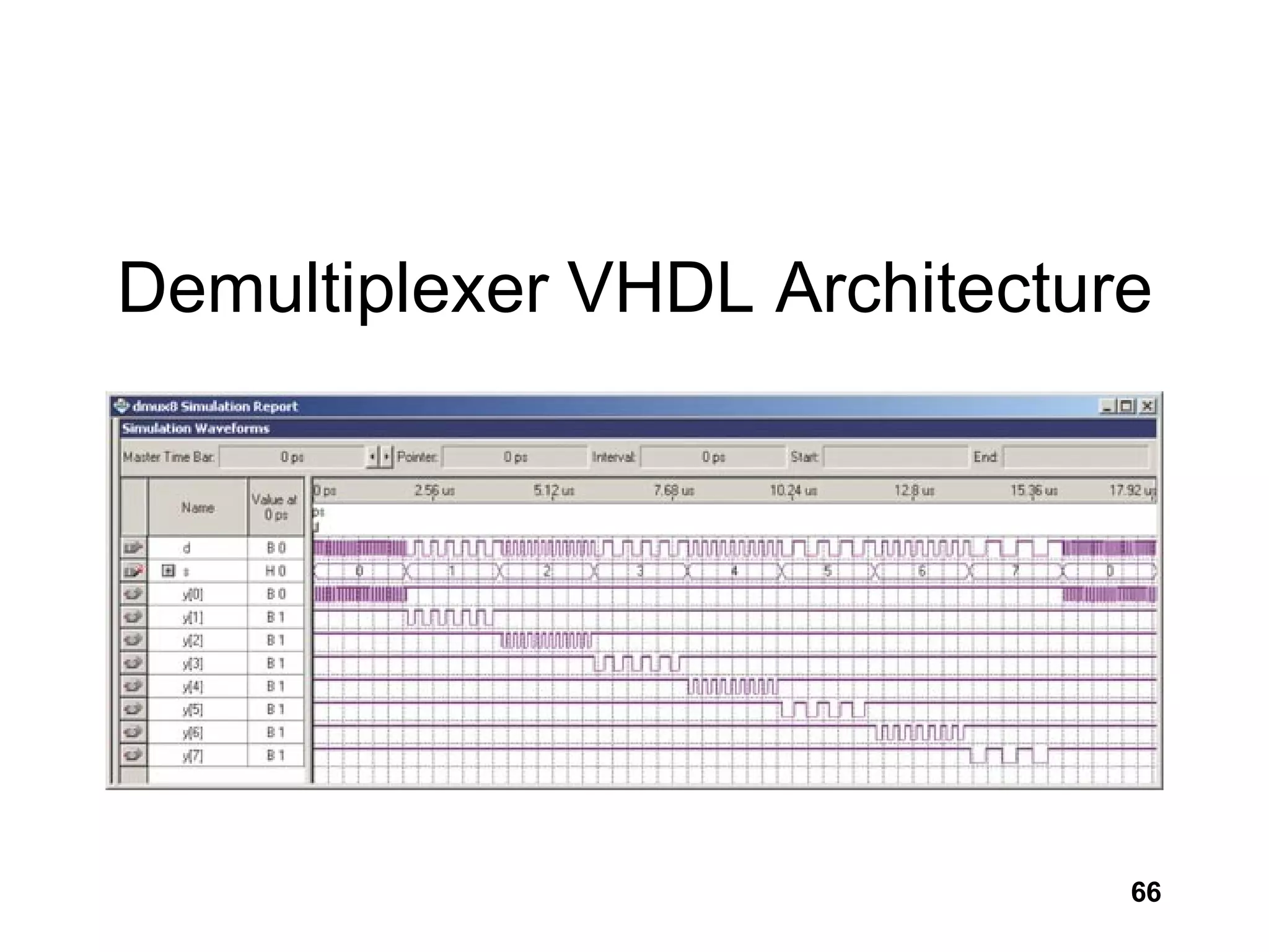

This document discusses various combinational logic circuits including decoders, encoders, multiplexers, and demultiplexers. It provides examples of their functionality and truth tables. It also shows how these circuits can be modeled in VHDL using constructs like concurrent signal assignment statements, select signal assignment statements, and case statements. Processes and sensitivity lists are discussed for modeling sequential logic. Applications like address decoding and time division multiplexing are also mentioned.