Download as PDF, PPTX
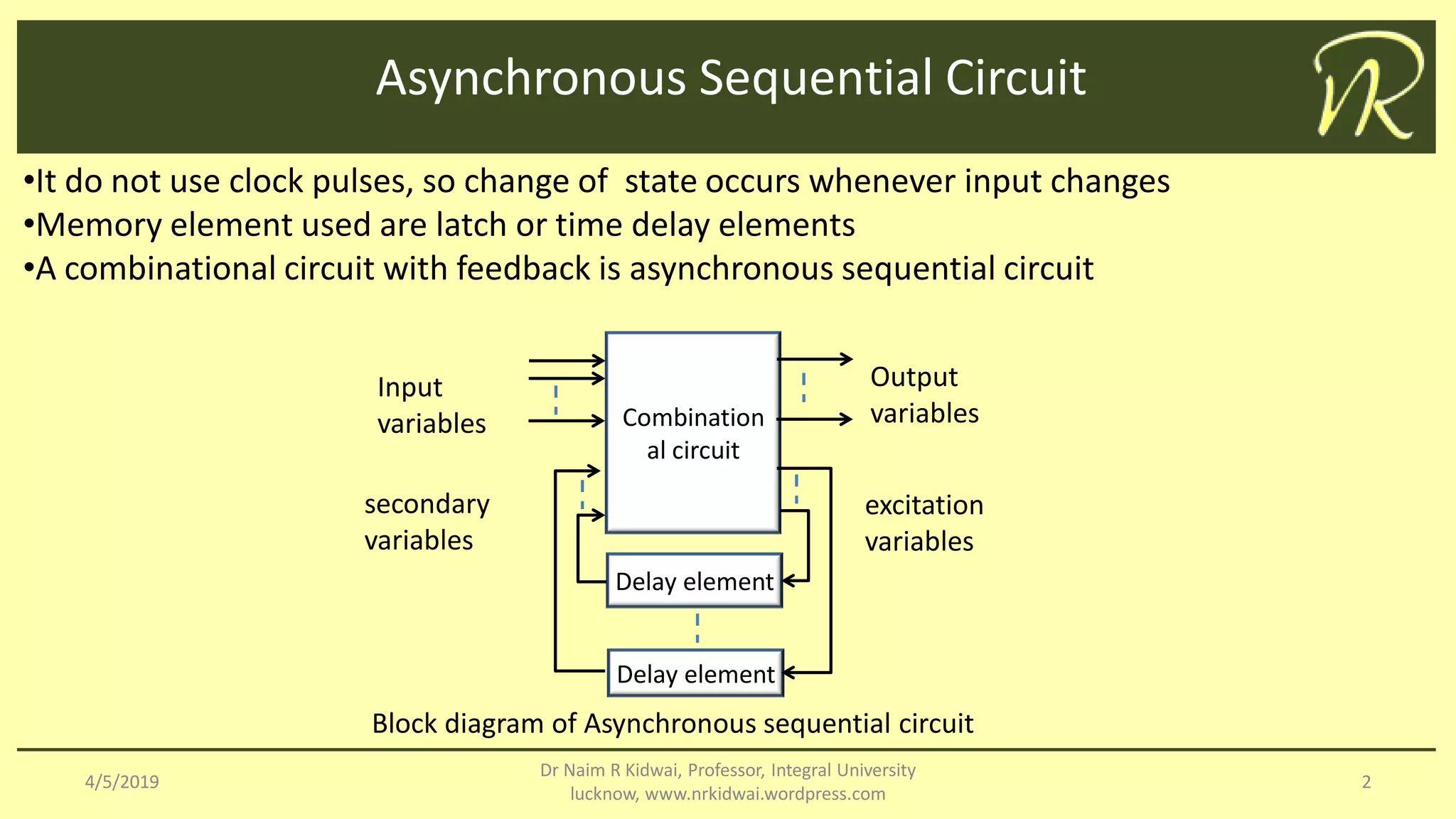
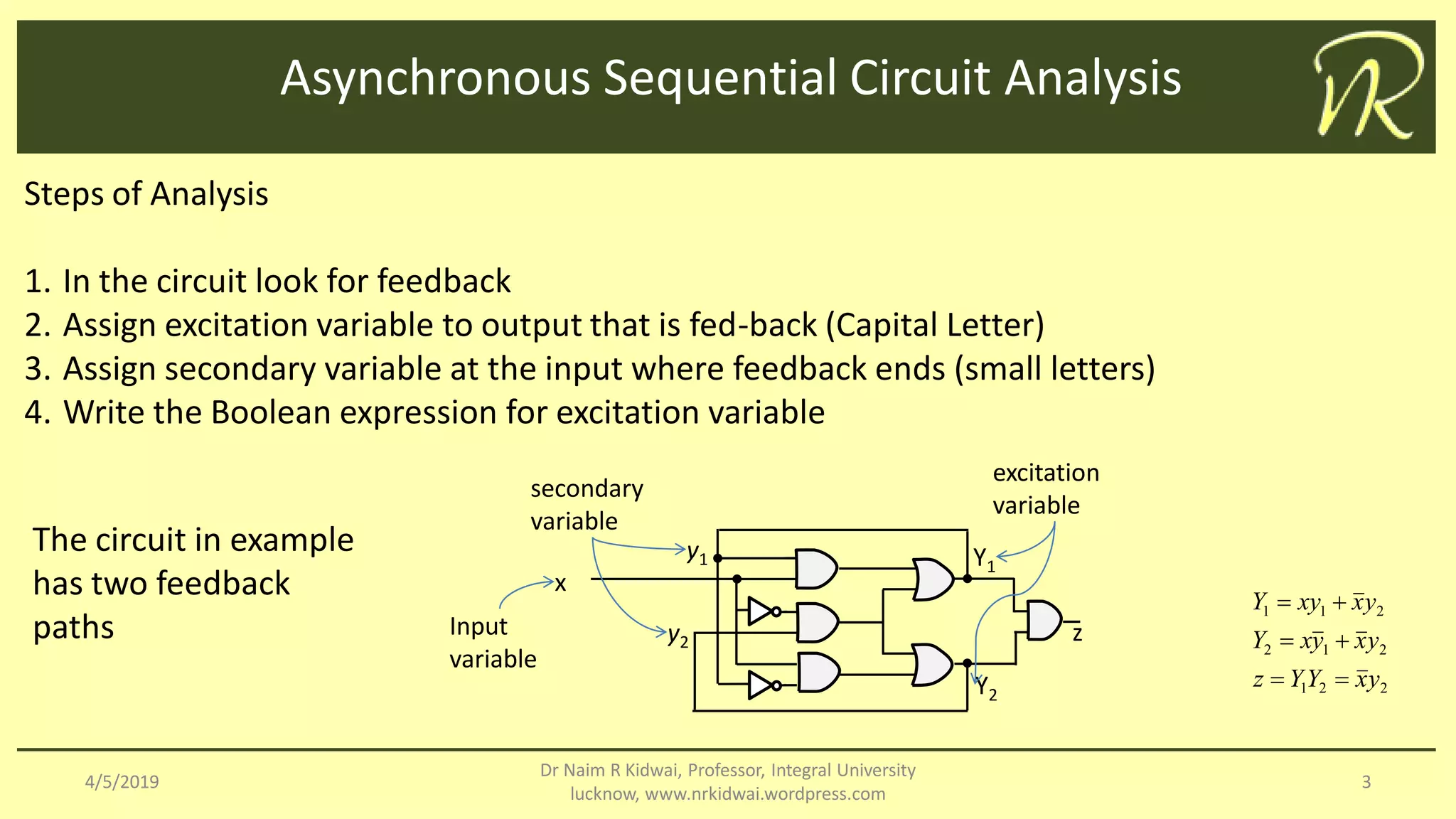
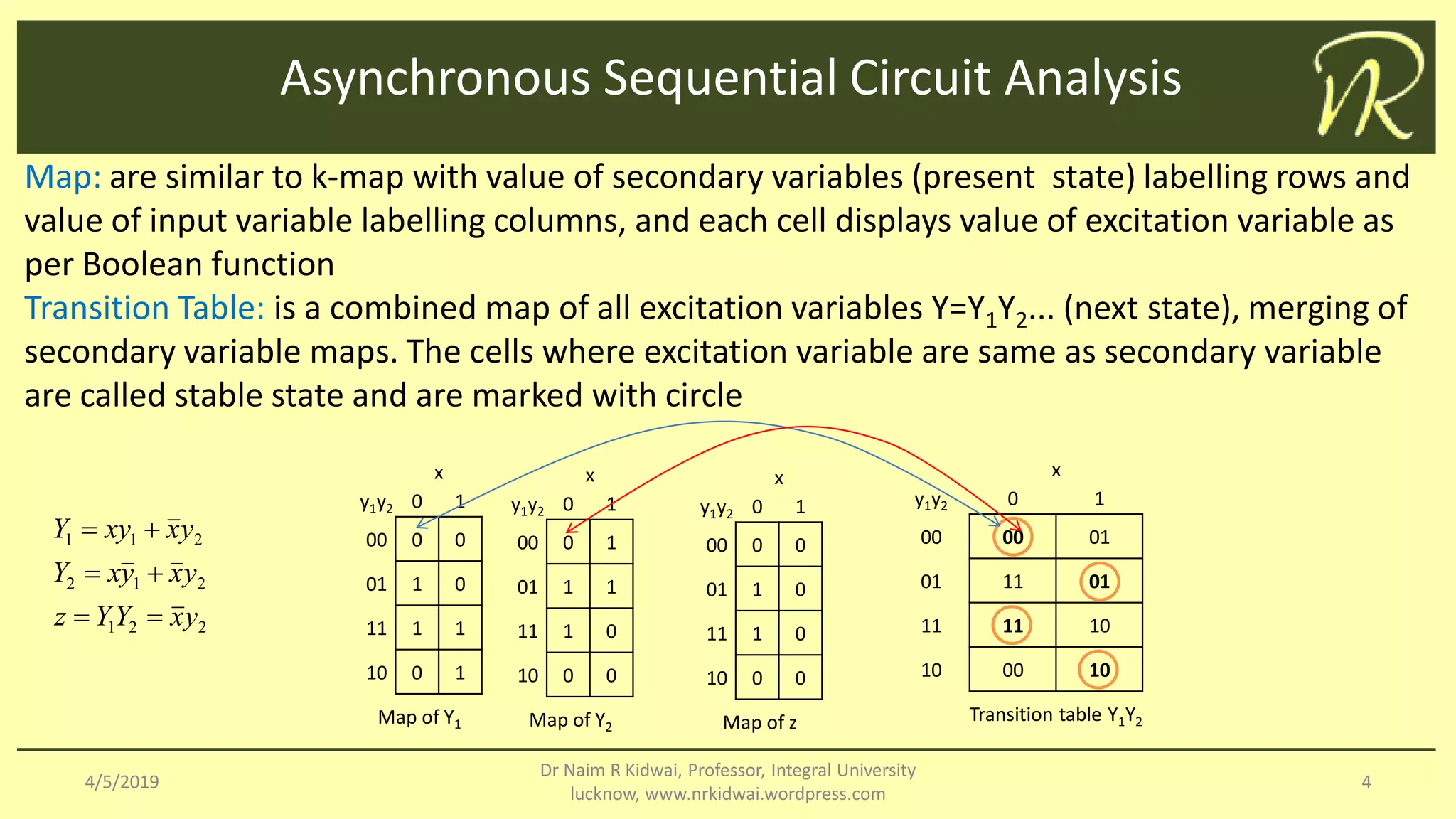
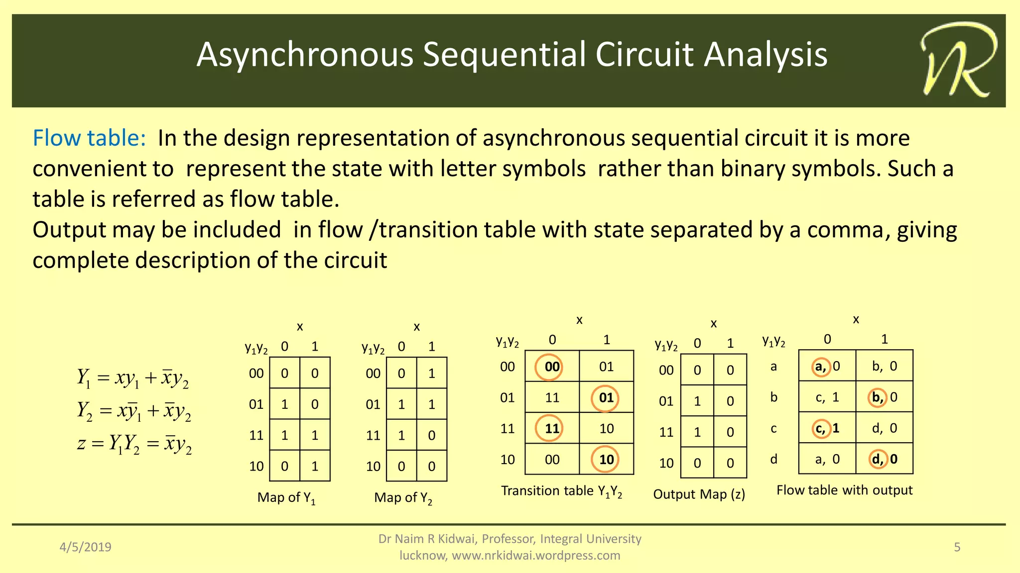

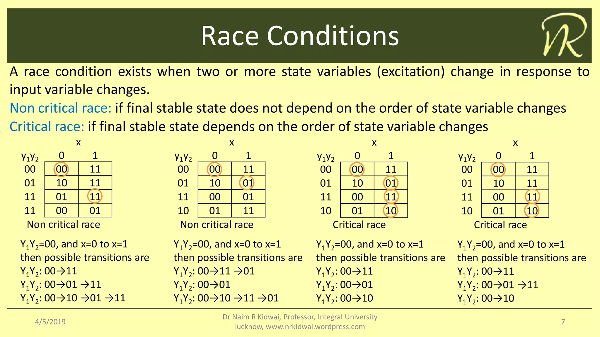

The document outlines the analysis and design of asynchronous sequential circuits, which operate without clock pulses and use feedback combinations of memory elements like latches. It discusses methodologies such as transition and flow tables to describe circuit behavior and highlights the significance of mapping states and variables. Additionally, it addresses race conditions, categorizing them as critical or non-critical based on the dependency of final stable states on the order of state changes.