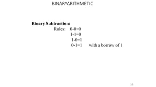
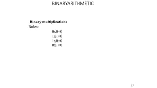
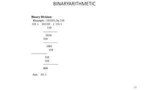
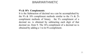
This document provides an overview of a computer organization course for first year BCA students. It covers topics like introduction to digital logic design, number systems, binary arithmetic operations, binary coded decimal, and non-weighted and weighted binary codes. The key concepts discussed include binary, octal, hexadecimal number conversions; addition, subtraction, multiplication and division in binary; 1's complement, 2's complement representations; and BCD and excess-3 coding schemes.
A numeral system (or system of numeration) is a writing system for expressing numbers; that is, a mathematical notation for representing numbers of a given set, using digits or other symbols in a consistent manner. It can be seen as the context that allows the symbols "11" to be interpreted as the binary symbol for three, the decimal symbol for eleven, or a symbol for other numbers in different bases.
Contents:
1.What is number system?
2.Conversions of number from one radix to another
3.Complements (1's, 2's, 9's, 10's)
4.Binary Arithmetic ( Addition, subtraction, multiplication, division)
FYBSC IT Digital Electronics Unit I Chapter I Number System and Binary Arithm...Arti Parab Academics
Number System:
Analog System, digital system, numbering system, binary number
system, octal number system, hexadecimal number system, conversion
from one number system to another, floating point numbers, weighted
codes binary coded decimal, non-weighted codes Excess – 3 code, Gray
code, Alphanumeric codes – ASCII Code, EBCDIC, ISCII Code,
Hollerith Code, Morse Code, Teletypewriter (TTY), Error detection
and correction, Universal Product Code, Code conversion.
The binary number system and digital codes are fundamental to computers and to digital electronics in general. You will learn Binary addition, subtraction, multiplication, and Division.
THE IMPORTANCE OF MARTIAN ATMOSPHERE SAMPLE RETURN.Sérgio Sacani
The return of a sample of near-surface atmosphere from Mars would facilitate answers to several first-order science questions surrounding the formation and evolution of the planet. One of the important aspects of terrestrial planet formation in general is the role that primary atmospheres played in influencing the chemistry and structure of the planets and their antecedents. Studies of the martian atmosphere can be used to investigate the role of a primary atmosphere in its history. Atmosphere samples would also inform our understanding of the near-surface chemistry of the planet, and ultimately the prospects for life. High-precision isotopic analyses of constituent gases are needed to address these questions, requiring that the analyses are made on returned samples rather than in situ.
What is greenhouse gasses and how many gasses are there to affect the Earth.moosaasad1975
What are greenhouse gasses how they affect the earth and its environment what is the future of the environment and earth how the weather and the climate effects.
A brief information about the SCOP protein database used in bioinformatics.
The Structural Classification of Proteins (SCOP) database is a comprehensive and authoritative resource for the structural and evolutionary relationships of proteins. It provides a detailed and curated classification of protein structures, grouping them into families, superfamilies, and folds based on their structural and sequence similarities.
(May 29th, 2024) Advancements in Intravital Microscopy- Insights for Preclini...Scintica Instrumentation
Intravital microscopy (IVM) is a powerful tool utilized to study cellular behavior over time and space in vivo. Much of our understanding of cell biology has been accomplished using various in vitro and ex vivo methods; however, these studies do not necessarily reflect the natural dynamics of biological processes. Unlike traditional cell culture or fixed tissue imaging, IVM allows for the ultra-fast high-resolution imaging of cellular processes over time and space and were studied in its natural environment. Real-time visualization of biological processes in the context of an intact organism helps maintain physiological relevance and provide insights into the progression of disease, response to treatments or developmental processes.
In this webinar we give an overview of advanced applications of the IVM system in preclinical research. IVIM technology is a provider of all-in-one intravital microscopy systems and solutions optimized for in vivo imaging of live animal models at sub-micron resolution. The system’s unique features and user-friendly software enables researchers to probe fast dynamic biological processes such as immune cell tracking, cell-cell interaction as well as vascularization and tumor metastasis with exceptional detail. This webinar will also give an overview of IVM being utilized in drug development, offering a view into the intricate interaction between drugs/nanoparticles and tissues in vivo and allows for the evaluation of therapeutic intervention in a variety of tissues and organs. This interdisciplinary collaboration continues to drive the advancements of novel therapeutic strategies.
Deep Behavioral Phenotyping in Systems Neuroscience for Functional Atlasing a...Ana Luísa Pinho
Functional Magnetic Resonance Imaging (fMRI) provides means to characterize brain activations in response to behavior. However, cognitive neuroscience has been limited to group-level effects referring to the performance of specific tasks. To obtain the functional profile of elementary cognitive mechanisms, the combination of brain responses to many tasks is required. Yet, to date, both structural atlases and parcellation-based activations do not fully account for cognitive function and still present several limitations. Further, they do not adapt overall to individual characteristics. In this talk, I will give an account of deep-behavioral phenotyping strategies, namely data-driven methods in large task-fMRI datasets, to optimize functional brain-data collection and improve inference of effects-of-interest related to mental processes. Key to this approach is the employment of fast multi-functional paradigms rich on features that can be well parametrized and, consequently, facilitate the creation of psycho-physiological constructs to be modelled with imaging data. Particular emphasis will be given to music stimuli when studying high-order cognitive mechanisms, due to their ecological nature and quality to enable complex behavior compounded by discrete entities. I will also discuss how deep-behavioral phenotyping and individualized models applied to neuroimaging data can better account for the subject-specific organization of domain-general cognitive systems in the human brain. Finally, the accumulation of functional brain signatures brings the possibility to clarify relationships among tasks and create a univocal link between brain systems and mental functions through: (1) the development of ontologies proposing an organization of cognitive processes; and (2) brain-network taxonomies describing functional specialization. To this end, tools to improve commensurability in cognitive science are necessary, such as public repositories, ontology-based platforms and automated meta-analysis tools. I will thus discuss some brain-atlasing resources currently under development, and their applicability in cognitive as well as clinical neuroscience.
Observation of Io’s Resurfacing via Plume Deposition Using Ground-based Adapt...Sérgio Sacani
Since volcanic activity was first discovered on Io from Voyager images in 1979, changes
on Io’s surface have been monitored from both spacecraft and ground-based telescopes.
Here, we present the highest spatial resolution images of Io ever obtained from a groundbased telescope. These images, acquired by the SHARK-VIS instrument on the Large
Binocular Telescope, show evidence of a major resurfacing event on Io’s trailing hemisphere. When compared to the most recent spacecraft images, the SHARK-VIS images
show that a plume deposit from a powerful eruption at Pillan Patera has covered part
of the long-lived Pele plume deposit. Although this type of resurfacing event may be common on Io, few have been detected due to the rarity of spacecraft visits and the previously low spatial resolution available from Earth-based telescopes. The SHARK-VIS instrument ushers in a new era of high resolution imaging of Io’s surface using adaptive
optics at visible wavelengths.
Earliest Galaxies in the JADES Origins Field: Luminosity Function and Cosmic ...Sérgio Sacani
We characterize the earliest galaxy population in the JADES Origins Field (JOF), the deepest
imaging field observed with JWST. We make use of the ancillary Hubble optical images (5 filters
spanning 0.4−0.9µm) and novel JWST images with 14 filters spanning 0.8−5µm, including 7 mediumband filters, and reaching total exposure times of up to 46 hours per filter. We combine all our data
at > 2.3µm to construct an ultradeep image, reaching as deep as ≈ 31.4 AB mag in the stack and
30.3-31.0 AB mag (5σ, r = 0.1” circular aperture) in individual filters. We measure photometric
redshifts and use robust selection criteria to identify a sample of eight galaxy candidates at redshifts
z = 11.5 − 15. These objects show compact half-light radii of R1/2 ∼ 50 − 200pc, stellar masses of
M⋆ ∼ 107−108M⊙, and star-formation rates of SFR ∼ 0.1−1 M⊙ yr−1
. Our search finds no candidates
at 15 < z < 20, placing upper limits at these redshifts. We develop a forward modeling approach to
infer the properties of the evolving luminosity function without binning in redshift or luminosity that
marginalizes over the photometric redshift uncertainty of our candidate galaxies and incorporates the
impact of non-detections. We find a z = 12 luminosity function in good agreement with prior results,
and that the luminosity function normalization and UV luminosity density decline by a factor of ∼ 2.5
from z = 12 to z = 14. We discuss the possible implications of our results in the context of theoretical
models for evolution of the dark matter halo mass function.
3. Digital logic design is a system in electrical
and computer engineering that uses simple
number values to produce input and output
operations.
3
INTRODUCTION TO DIGITAL LOGIC DESIGN
4. INTRODUCTION TO DIGITAL LOGIC DESIGN
4
Advantages:
•A digital computer stores data in terms of digits
(numbers) and proceeds in discrete steps from one state
to the next.
•The states of a digital computer typically involve binary
digits which may take the form of the presence or
absence of magnetic markers in a storage medium , on-
off switches or relays. In digital computers, even letters,
words and whole texts are represented digitally.
6. NUMBER BASE CONVERSION
6
Binary to Decimal Conversion:
It is by the positional weights method . In this
method,each binary digit of the no. is multiplied by its position
weight . The product terms are added to obtain the decimal no.
7. NUMBER BASE CONVERSION
7
Binary to Octal conversion:
Starting from the binary pt. make groups of 3 bits each,
on either side of the binary pt, & replace each 3 bit binary
group by the equivalent octaldigit.
8. NUMBER BASE CONVERSION
8
Binary to Hexadecimal conversion:
For this make groups of 4 bits each , on either side of the
binary pt & replace each 4 bit group by the equivalent
hexadecimal digit.
9. NUMBER BASE CONVERSION
9
Decimal to Binary conversion:
I.method: is for small no.s The values of various powers of 2
need to be remembered. for conversion of larger no.s have a
table of powers of 2 known as the sum of weights method. The
set of binary weight values whose sum is equal to the decimal
no. is determined.
II.method : It converts decimal integer no. to binary integer no
by successive division by 2 & the decimal fraction is converted
to binary fraction by double –dabble method
10. NUMBER BASE CONVERSION
10
Octal to decimal Conversion:
Multiply each digit in the octal no by the weight of
its position&add all the product termsDecimal value of the octal
no.
11. NUMBER BASE CONVERSION
11
Decimal to Octal Conversion:
To convert a mixed decimal no. To a mixed octal no.
convert the integer and fraction parts separately. To convert
decimal integer no. to octal, successively divide the given no by
8 till the quotient is 0. The last remainder is the MSD .The
remainder read upwards give the equivalent octal integer no. T
o
convert the given decimal fraction to octal, successively
multiply the decimal fraction&the subsequent decimal fractions
by 8 till the product is 0 or till the required accuracy is the
MSD. The integers to the left of the octal pt read downwards
give the octal fraction.
12. NUMBER BASE CONVERSION
12
Decimal to Hexadecimal conversion:
It is successively divide the given decimal no. by 16
till the quotient is zero. The last remainder is the MSB. The
remainder read from bottom to top gives the equivalent
hexadecimal integer. To convert a decimal fraction to
hexadecimal successively multiply the given decimal fraction &
subsequent decimal fractions by 16, till the product is zero. Or
till the required accuracy is obtained,and collect all the integers
to the left of decimal pt. The first integer is MSB & the integer
read from top to bottom give the hexadecimal fraction known as
the hexadabble method.
13. NUMBER BASE CONVERSION
13
Octal to hexadecimal conversion:
The simplest way is to first convert the given octal no. to
binary & then the binary no. to hexadecimal.
14. FINDING THE BASE OF THE NUMBERSYSTEM
14
• Find r such that (121)r=(144)8, where r and 8 are the bases
1*82 + 4*8+4*80 =64+32+4 =100
1*r2+2*r+1*r0 = r2+2r+1=(r+1)2
(r+1)2=100
r+1=10
r=9
19. BINARYARITHMETIC
19
9’s & 10’s Complements:
It is the Subtraction of decimal no.s can be accomplished by
the 9’s & 10’s compliment methods similar to the 1’s & 2’s
compliment methods of binary . the 9’s compliment of a
decimal no. is obtained by subtracting each digit of that
decimal no. from 9. The 10’s compliment of a decimal no is
obtained by adding a 1 to its 9’s compliment.
20. 1’s compliment of n number:
It is obtained by simply complimenting each bit of the
no,.& also , 1’s comp of a no, is subtracting each bit of the
no. form 1.This complemented value rep the –ve of the
original no. One of the difficulties of using 1’s comp is its
rep o f zero.Both 00000000 & its 1’s comp 11111111 rep
zero.The 00000000 called +ve zero& 11111111called –ve
zero.
20
BINARYARITHMETIC
21. BINARYARITHMETIC
21
1’s compliment arithmetic:
In 1’s comp subtraction, add the 1’s comp of
the subtrahend to the minuend. If there is a carryout , bring
the carry around & add it to the LSB called the end around
carry. Look at the sign bit (MSB) . If this is a 0, the result
is +ve & is in true binary. If the MSB is a 1 ( carry or no
carry ), the result is –ve & is in its is comp form .Take its 1’s
comp to get the magnitude inn binary.
22. BINARYARITHMETIC
22
9’s & 10’s Complements:
It is the Subtraction of decimal no.s can be accomplished by
the 9’s & 10’s compliment methods similar to the 1’s & 2’s
compliment methods of binary . the 9’s compliment of a
decimal no. is obtained by subtracting each digit of that
decimal no. from 9. The 10’s compliment of a decimal no is
obtained by adding a 1 to its 9’s compliment.
23. Methods of obtaining 2’s comp of a no:
In 3 ways
By obtaining the 1’s comp of the given no. (by changing all 0’s to
1’s & 1’s to 0’s) & then adding 1.
By subtracting the given n bit no N from 2n
Starting at the LSB , copying down each bit upto & including the
first 1 bit encountered , and complimenting the remaining bits.
23
BINARYARITHMETIC
24. BINARYARITHMETIC
24
2’s compliment Arithmetic:
The 2’s comp system is used to rep –ve no.s using modulus
arithmetic . The word length of a computer is fixed. i.e, if a 4 bit no.
is added to another 4 bit no . the result will be only of 4 bits. Carry
if any , from the fourth bit will overflow called the Modulus
arithmetic.
Ex:1100+1111=1011
25. BINARYARITHMETIC
25
9’s & 10’s Complements:
.
It is the Subtraction of decimal no.s can be accomplished by
the 9’s & 10’s compliment methods similar to the 1’s & 2’s
compliment methods of binary . the 9’s compliment of a
decimal no. is obtained by subtracting each digit of that
decimal no. from 9. The 10’s compliment of a decimal no is
obtained by adding a 1 to its 9’s compliment
26. 1’s compliment of n number:
It is obtained by simply complimenting each bit of the
no,.& also , 1’s comp of a no, is subtracting each bit of the
no. form 1.This complemented value rep the –ve of the
original no. One of the difficulties of using 1’s comp is its
rep o f zero.Both 00000000 & its 1’s comp 11111111 rep
zero.The 00000000 called +ve zero& 11111111called –ve
zero.
26
BINARYARITHMETIC
27. BINARYARITHMETIC
27
1’s compliment arithmetic:
In 1’s comp subtraction, add the 1’s comp of
the subtrahend to the minuend. If there is a carryout , bring
the carry around & add it to the LSB called the end around
carry. Look at the sign bit (MSB) . If this is a 0, the result
is +ve & is in true binary. If the MSB is a 1 ( carry or no
carry ), the result is –ve & is in its is comp form .Take its 1’s
comp to get the magnitude inn binary.
28. BINARYARITHMETIC
28
9’s & 10’s Complements:
It is the Subtraction of decimal no.s can be accomplished by
the 9’s & 10’s compliment methods similar to the 1’s & 2’s
compliment methods of binary . the 9’s compliment of a
decimal no. is obtained by subtracting each digit of that
decimal no. from 9. The 10’s compliment of a decimal no is
obtained by adding a 1 to its 9’s compliment.
29. Weighted Codes:-
The weighted codes are those that obey the position
weighting principle, which states that the position of each
number represent a specific weight. In these codes each
decimal digit is represented by a group of four bits.
In weighted codes, each digit is assigned a specific weight
according to its position. For example, in 8421/BCD code,
1001 the weights of 1, 1, 0, 1 (from left to right) are 8, 4, 2
and 1 respectively.
Examples:8421,2421 are all weighted codes.
29
BINARY WEIGHTED AND NON- WEIGHTED CODES
30. BINARY WEIGHTED AND NON- WEIGHTED CODES
30
Non-weightedcodes:
The non-weighted codes are not positionally weighted . In other
words codes that are not assigned with any weight to each digit
position.
Examples:Excess-3(XS-3) and Gray Codes.
31. BCD Addition:
It is individually adding the corresponding digits of the
decimal no,s expressed in 4 bit binary groups starting from
the LSD . If there is no carry & the sum term is not an illegal
code , no correction is needed.If there is a carry out of one
group to the next group or if the sum term is an illegal code
then 610(0100) is added to the sum term of that group &the
resulting carry is added to the next group.
31
BINARY CODED DECIMAL
32. BCD Subtraction:
Performed by subtracting the digits of each 4 bit groupof
the subtrahend the digits from the corresponding 4- bit
group of the minuend in binary starting from the LSD . if
there is no borrow from the next group , then 610(0110)is
subtracted from the difference term of thisgroup.
32
BINARY CODED DECIMAL
33. Excess-3Addition:
Add the xs-3 no.s by adding the 4 bit groups in each column starting
from the LSD. If there is no carry starting from the addition of any of the 4-bit
groups , subtract 0011 from the sum term of those groups ( because when 2
decimal digits are added in xs-3 & there is no carry , result in xs-6). If there is a
carry out, add 0011 to the sum term of those groups( because when there is a
carry, the invalid states are skipped and the result is normal binary).
33
BINARY CODED DECIMAL
34. Excess -3 (XS-3) Subtraction:
Subtract the xs-3 no.s by subtracting each 4 bit group of the subtrahend from
the corresponding 4 bit group of the minuend starting form the LSD .if there is
no borrow from the next 4-bit group add 0011 to the difference term of such
groups (because when decimal digits are subtracted in xs-3 & there is no borrow
, result is normal binary). I f there is a borrow , subtract 0011 from the difference
term(b coz taking a borrow is equivalent to adding six invalid states , result is in
xs-6)
34
BINARY CODED DECIMAL
35. Representation of signed no.s binary
arithmetic in computers:
Two ways of rep signed no.s
Sign Magnitude form
Complemented form
Two complimented forms
1’s compliment form
2’s compliment form
35
SIGNED BINARY NUMBERS
36. SIGNED BINARY NUMBERS
36
Error – Detecting codes:When binary data is transmitted &
processed,it is susceptible to noise that can alter or distort its
contents. The 1’s may get changed to 0’s & 1’s .because digital
systems must be accurate to the digit, error can pose a problem.
Several schemes have been devised to detect the occurrence of a
single bit error in a binary word, so that whenever such an error
occurs the concerned binary word can be corrected &
retransmitted.
37. ERROR DETECTING AND CORRECTING CODES
37
• Introduction:
• When we talk about digital systems, be it a digital computer or a
digital communication set-up, the issue of error detection and
correction is of great practical significance.
• Errors creep into the bit stream owing to noise or other
impairments during the course of its transmission from the
transmitter to the receiver.
• While the addition of redundant bits helps in achieving the goal of
making transmission of information from one place to another
error free or reliable, it also makes it inefficient.
38. ERROR DETECTING AND CORRECTING CODES
38
• Some Common Error Detecting and CorrectingCodes
• Parity Code
• Repetition Code
• Cyclic Redundancy Check Code
• Hamming Code
39. ERROR DETECTING AND CORRECTING CODES
39
• Parity Code:
• A parity bit is an extra bit added to a string of data bits in order to detect
any error that might have crept into it while it was being stored or
processed and moved from one place to another in a digital system.
• This simple parity code suffers from two limitations. Firstly, it cannot
detect the error if the number of bits having undergone a change is even.
• Repetition Code:
• The repetition code makes use of repetitive transmission of each data bit
in the bit stream. In the case of threefold repetition, ‘1’ and ‘0’ would be
transmitted as ‘111’ and ‘000’ respectively.
• The repetition code is highly inefficient and the information throughput
drops rapidly as we increase the number of times each data bit needs to
be repeated to build error detection and correction capability.
40. ERROR DETECTING AND CORRECTING CODES
• Cyclic RedundancyCheck Code:
• Cyclic redundancy check (CRC) codes provide a reasonably high level of
protection at low redundancy level.
• The probability of error detection depends upon the number of check
bits, , used to construct the cyclic code. It is 100 % for single-bit and two-
bit errors. It is also 100 % when an odd number of bits are in error and the
error bursts have a length less than .
• The probability of detection reduces to for an error burst
for an error burst length
length equal to , and to
greater than .
40
41. ERROR DETECTING AND CORRECTING CODES
41
• Hamming Code:
• An increase in the number of redundant bits added to message bits can
enhance the capability of the code to detect and correct errors.
• If sufficient number of redundant bits arranged such that different error
bits produce different error results, then it should be possible not only to
detect the error bit but also to identify its location.
• In fact, the addition of redundant bits alters the ‘distance’ code parameter,
which has come to be known as the Hamming distance.
• Hamming Distance:
• The Hamming distance is nothing but the number of bit disagreements
between two code words.
42. ERROR DETECTING AND CORRECTING CODES
42
• For example, the addition of single-bit parity results in a code with a
Hamming distance of at least 2.
• The smallest Hamming distance in the case of a threefold repetition code
would be 3.
• Hamming noticed that an increase in distance enhanced the code’s ability
to detect and correct errors.
• Hamming’s code was therefore an attempt at increasing the Hamming
distance and at the same time having as high an information throughput
rate as possible.
43. ERROR DETECTING AND CORRECTING CODES
43
• The algorithm for writing the generalized Hamming code is as follows:
1. The generalized form of code is P1P2D1P3D2D3D4P4D5D6D7D8D9D10D11P5.......,
where P and D respectively represent parity and data bits.
2. We can see from the generalized form of the code that all bit positions
that are powers of 2 (positions 1, 2, 4, 8, 16 ...) are used as parity bits.
3. All other bit positions (positions 3, 5, 6, 7, 9, 10, 11 ...) are used to encode
data.
4. Each parity bit is allotted a group of bits from the data bits in the code
word, and the value of the parity bit (0 or 1) is used to give it certain
parity.
44. ERROR DETECTING AND CORRECTING CODES
44
1. Groups are formed by first checking bits and then alternately skipping
and checking bits following the parity bit. Here, is the position of the
parity bit; 1 for P1, 2 for P2, 4 for P3, 8 for P4 and soon.
2. For example, for the generalized form of code given above, various
groups of bits formed with different parity bits would be P1D1D2D4D5....,
P2D1D3D4D6D7...., P3D2D3D4D8D9...., P4D5D6D7D8D9D10D11...., and so on. T
o
illustrate the formation of groups further, let us examine the group
corresponding to parity bit P3.
3. Now, the position of P3 is at number 4. In order to form the group, we check
the first three bits N-1=3 and then follow it up by alternately skipping and
checking four bits (N=4).
45. ERROR DETECTING AND CORRECTING CODES
• The Hamming code is capable of correcting single-bit errors on messages of
any length.
• Although the Hamming code can detect two-bit errors, it cannot give the error
locations.
• The number of parity bits required to be transmitted along with the message,
however,depends upon the message length.
• The number of parity bits n required to encode m message bits is the smallest
integer that satisfies the condition .
• The most commonly used Hamming code is the one that has a code word
length of seven bits with four message bits and three parity bits.
• It is also referred to as the Hamming (7, 4) code
45
46. ERROR DETECTING AND CORRECTING CODES
• The code word sequence for this code is written as P1P2D1P3D2D3D4, with
P1, P2 and P3 being the parity bits and D1, D2, D3 and D4 being the data bits.
• Generation of Hamming Code:
46