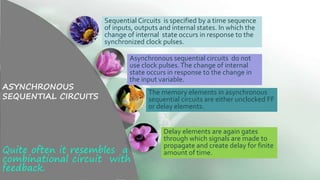
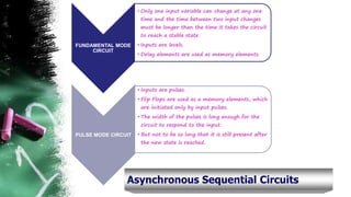
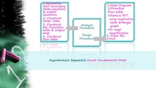
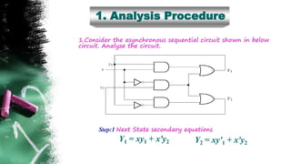
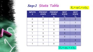
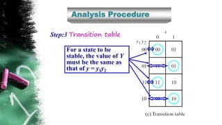
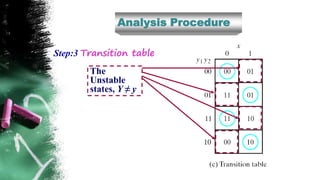
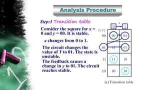
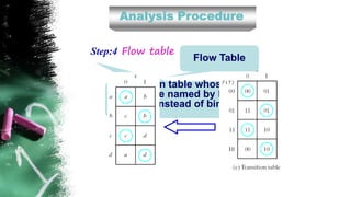
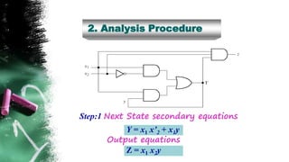
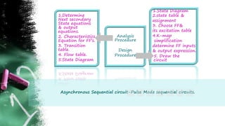
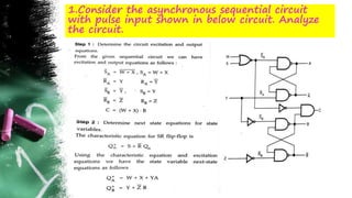
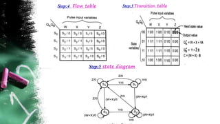
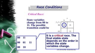
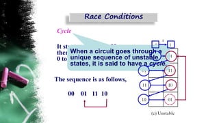
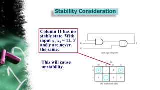
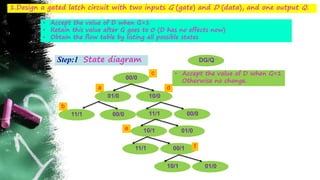
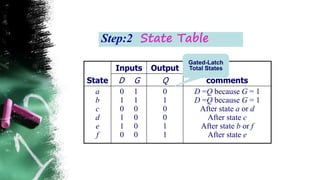
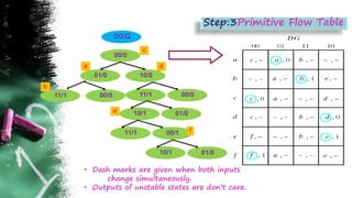
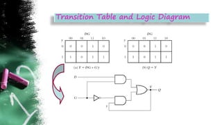
UNIT 4
ASYNCHRONOUS SEQUENTIAL CIRCUIT
PRESENTED
BY
Mrs. P.SIVALAKSHMI
ASSISTANT PROFESSOR
ECE/RMKCET
Types of Asynchronous Sequential Circuits
Analysis & Design of Pulse mode circuits
Analysis & Design of Fundamental mode
circuits
Design Of Hazard free Switching
Circuits
TOPICS TO BE DISCUSSED
ASYNCHRONOUS
SEQUENTIAL CIRCUITS
Quite often it resembles a
combinational circuit with
feedback.
Sequential Circuits is specified by a time sequence
of inputs, outputs and internal states. In which the
change of internal state occurs in response to the
synchronized clock pulses.
Asynchronous sequential circuits do not
use clock pulses.The change of internal
state occurs in response to the change in
the input variable.
The memory elements in asynchronous
sequential circuits are either unclocked FF
or delay elements.
Delay elements are again gates
through which signals are made to
propagate and create delay for finite
amount of time.
Asynchronous Sequential Circuits
When an input
variable changes
in value, the y
secondary
variables do not
change
instantaneously.
In steady-state
condition, the
y's and the Y's
are the same,
but during
transition they
are not.
Asynchronous Sequential Circuits
• Higher speed
• More economical
FUNDAMENTAL MODE
CIRCUIT
• Only one input variable can change at any one
time and the time between two input changes
must be longer than the time it takes the circuit
to reach a stable state.
• Inputs are levels.
• Delay elements are used as memory elements.
PULSE MODE CIRCUIT
• Inputs are pulses.
• Flip Flops are used as a memory elements, which
are initiated only by input pulses.
• The width of the pulses is long enough for the
circuit to respond to the input.
• But not to be so long that it is still present after
the new state is reached.
Asynchronous Sequential Circuits
Asynchronous Sequential circuit-Fundamental Mode
1.Determine
Next secondary
State equations
& output
equations.
2. Construct
State Table.
3. Construct
the Transition
table & output
map.
4. Construct
flow table.
Analysis
Procedure
Design
Procedure
2.Primitive
Flow table.
3.Reduce PFT
using Implication
table &Merger
graph
4.K-map
simplification
5. Draw the
circuit
1.State Diagram
1. Analysis Procedure
1.Consider the asynchronous sequential circuit shown in below
circuit. Analyze the circuit.
Y1 = xy1 + x'y2 Y2 = xy'1 + x'y2
Step:1 Next State secondary equations
Step:2 State Table
INPUTS
X
PRESENT
STATE
y1
PRESENT
STATE
y2
NEXT
STATE
Y1
NEXT
STATE
Y2
0 0 0 0 0
0 0 1 1 1
0 1 1 1 1
0 1 0 0 0
1 0 0 0 1
1 0 1 0 1
1 1 1 1 0
1 1 0 1 0
Y1 = xy1 + x'y2
Y2 = xy'1 + x'y2
Analysis Procedure
Y1 = xy1 + x'y2 Y2 = xy'1 + x'y2
Step:3 Transition table
Analysis Procedure
For a state to be
stable, the value of Y
must be the same as
that of y = y1y2
Step:3 Transition table
Analysis Procedure
The
Unstable
states, Y ≠ y
Step:3 Transition table
Analysis Procedure
Consider the square for x =
0 and y = 00. It is stable.
x changes from 0 to 1.
The circuit changes the
value of Y to 01. The state is
unstable.
The feedback causes a
change in y to 01. The circuit
reaches stable.
Step:3 Transition table
Analysis Procedure
In general, if a change in
the input takes the circuit
to an unstable state, y will
change until it reaches a
stable state.
Step:3 Transition table
Transition table whose
states are named by letter
symbol instead of binary
values.
Flow Table
Analysis Procedure
Step:4 Flow table
It is called primitive flow table
because it has only one stable
state in each row.
It is a flow table with more than
one stable state in the same
row.
Analysis Procedure
Step:4 Flow table or Primitive Flow table
2. Analysis Procedure
Y = x1 x’2 + x1y
Step:1 Next State secondary equations
Output equations
Z = x1 x2y
Step:2 State Table
INPUTS
X1 X2
PRESENT
STATE
NEXT
STATE
OUTPUT
0 0 0 0 0
0 1 0 0 0
1 1 0 0 0
1 0 0 1 0
0 0 1 0 0
0 1 1 0 0
1 1 1 1 1
1 0 1 1 0
Y = x1 x’2 + x1y
Z = x1 x2y
Step:3 Transition table & output map.
Step:4 Flow table
Asynchronous Sequential circuit-Pulse Mode sequential circuits.
1.Determine
Next secondary
State equations
& output
equations.
2. Characteristics
Equation for FF’s.
3. Transition
table.
4. Flow table.
5.State Diagram
Analysis
Procedure
Design
Procedure
2.state table &
assignment
3. Choose FF&
its excitation table
4.K-map
simplification
determine FF inputs
& output expression.
5. Draw the
circuit
1.State Diagram
1.Consider the asynchronous sequential circuit
with pulse input shown in below circuit. Analyze
the circuit.
Step:2 State Table QA
+ = W+X+YA
QB
+ = Y+Z’B
C = (W+X).B
Step:2 State Table QA
+ = W+X+YA
QB
+ = Y+Z’B
C = (W+X).B
Step:3 Transition tableStep:4 Flow table
Step:5 state diagram
Two or more binary state
variables change value in
response to a change in an input
variable
Noncritical Race:
State variables change from 00
to 11. The possible transition
could be
00 11
00 01 11
00 10 11
It is a noncritical race.
The final stable state that
the circuit reaches does
not depend on the order
in which the state
variables change.
Race Conditions
Critical Race:
State variables
change from 00 to
11. The possible
transition could be
00 11
00 01 11
00 10
It is a critical race. The
final stable state
depends on the order in
which the state
variables change.
Race Conditions
Race Conditions
Cycle
It starts with y1 y2 =00,
then input changes from
0 to 1.
00 01 11 10
When a circuit goes through a
unique sequence of unstable
states, it is said to have a cycle.
The sequence is as follows,
Stability Consideration
Column 11 has no
stable state. With
input x1 x2 = 11, Y
and y are never
the same.
This will cause
unstability.
Asynchronous Sequential circuit-Fundamental Mode
1.Determine
Next secondary
State equations
& output
equations.
2. Construct
State Table.
3. Construct
the Transition
table & output
map.
4. Construct
flow table.
Analysis
Procedure
Design
Procedure
2.Primitive
Flow table.
3.Reduce PFT
using Implication
table &Merger
graph
4.K-map
simplification
5. Draw the
circuit
1.State Diagram
1.Design a gated latch circuit with two inputs G (gate) and D (data), and one output Q.
• Accept the value of D when G=1
• Retain this value after G goes to 0 (D has no effects now)
• Obtain the flow table by listing all possible states
DG/Q
00/0
01/0 10/0
Step:1 State diagram
• Accept the value of D when G=1
Otherwise no change.
11/1 00/0 11/1 00/0
10/1 01/0
11/1 00/1
10/1 01/0
a
b
c
d
e
f
State
Inputs Output
commentsD G Q
a
b
c
d
e
f
0 1
1 1
0 0
1 0
1 0
0 0
0
1
0
0
1
1
D =Q because G = 1
D =Q because G = 1
After state a or d
After state c
After state b or f
After state e
Gated-Latch
Total States
Step:2 State Table
• Dash marks are given when both inputs
change simultaneously.
• „Outputs of unstable states are don’t care.
Step:3Primitive Flow Table
DG/Q
00/0
01/0 10/0
11/1 00/0 11/1 00/0
10/1 01/0
11/1 00/1
10/1 01/0
a
b
c
d
e
f
Step:4Reduction of the Primitive Flow TableTwo of more rows in the primitive flow table can
be merged into one row if there are non-
conflicting states and outputs in each of the
columns.
Reduction of the Primitive Flow Table
Transition Table and Logic Diagram
Asynchronous Sequential Circuit-Unit 4 ppt

Asynchronous Sequential Circuit-Unit 4 ppt

  • 1.
    UNIT 4 ASYNCHRONOUS SEQUENTIALCIRCUIT PRESENTED BY Mrs. P.SIVALAKSHMI ASSISTANT PROFESSOR ECE/RMKCET
  • 2.
    Types of AsynchronousSequential Circuits Analysis & Design of Pulse mode circuits Analysis & Design of Fundamental mode circuits Design Of Hazard free Switching Circuits TOPICS TO BE DISCUSSED
  • 3.
    ASYNCHRONOUS SEQUENTIAL CIRCUITS Quite oftenit resembles a combinational circuit with feedback. Sequential Circuits is specified by a time sequence of inputs, outputs and internal states. In which the change of internal state occurs in response to the synchronized clock pulses. Asynchronous sequential circuits do not use clock pulses.The change of internal state occurs in response to the change in the input variable. The memory elements in asynchronous sequential circuits are either unclocked FF or delay elements. Delay elements are again gates through which signals are made to propagate and create delay for finite amount of time.
  • 5.
    Asynchronous Sequential Circuits Whenan input variable changes in value, the y secondary variables do not change instantaneously.
  • 6.
    In steady-state condition, the y'sand the Y's are the same, but during transition they are not. Asynchronous Sequential Circuits • Higher speed • More economical
  • 7.
    FUNDAMENTAL MODE CIRCUIT • Onlyone input variable can change at any one time and the time between two input changes must be longer than the time it takes the circuit to reach a stable state. • Inputs are levels. • Delay elements are used as memory elements. PULSE MODE CIRCUIT • Inputs are pulses. • Flip Flops are used as a memory elements, which are initiated only by input pulses. • The width of the pulses is long enough for the circuit to respond to the input. • But not to be so long that it is still present after the new state is reached. Asynchronous Sequential Circuits
  • 8.
    Asynchronous Sequential circuit-FundamentalMode 1.Determine Next secondary State equations & output equations. 2. Construct State Table. 3. Construct the Transition table & output map. 4. Construct flow table. Analysis Procedure Design Procedure 2.Primitive Flow table. 3.Reduce PFT using Implication table &Merger graph 4.K-map simplification 5. Draw the circuit 1.State Diagram
  • 9.
    1. Analysis Procedure 1.Considerthe asynchronous sequential circuit shown in below circuit. Analyze the circuit. Y1 = xy1 + x'y2 Y2 = xy'1 + x'y2 Step:1 Next State secondary equations
  • 10.
    Step:2 State Table INPUTS X PRESENT STATE y1 PRESENT STATE y2 NEXT STATE Y1 NEXT STATE Y2 00 0 0 0 0 0 1 1 1 0 1 1 1 1 0 1 0 0 0 1 0 0 0 1 1 0 1 0 1 1 1 1 1 0 1 1 0 1 0 Y1 = xy1 + x'y2 Y2 = xy'1 + x'y2
  • 11.
    Analysis Procedure Y1 =xy1 + x'y2 Y2 = xy'1 + x'y2 Step:3 Transition table
  • 12.
    Analysis Procedure For astate to be stable, the value of Y must be the same as that of y = y1y2 Step:3 Transition table
  • 13.
    Analysis Procedure The Unstable states, Y≠ y Step:3 Transition table
  • 14.
    Analysis Procedure Consider thesquare for x = 0 and y = 00. It is stable. x changes from 0 to 1. The circuit changes the value of Y to 01. The state is unstable. The feedback causes a change in y to 01. The circuit reaches stable. Step:3 Transition table
  • 15.
    Analysis Procedure In general,if a change in the input takes the circuit to an unstable state, y will change until it reaches a stable state. Step:3 Transition table
  • 16.
    Transition table whose statesare named by letter symbol instead of binary values. Flow Table Analysis Procedure Step:4 Flow table
  • 17.
    It is calledprimitive flow table because it has only one stable state in each row. It is a flow table with more than one stable state in the same row. Analysis Procedure Step:4 Flow table or Primitive Flow table
  • 18.
    2. Analysis Procedure Y= x1 x’2 + x1y Step:1 Next State secondary equations Output equations Z = x1 x2y
  • 19.
    Step:2 State Table INPUTS X1X2 PRESENT STATE NEXT STATE OUTPUT 0 0 0 0 0 0 1 0 0 0 1 1 0 0 0 1 0 0 1 0 0 0 1 0 0 0 1 1 0 0 1 1 1 1 1 1 0 1 1 0 Y = x1 x’2 + x1y Z = x1 x2y
  • 20.
    Step:3 Transition table& output map. Step:4 Flow table
  • 21.
    Asynchronous Sequential circuit-PulseMode sequential circuits. 1.Determine Next secondary State equations & output equations. 2. Characteristics Equation for FF’s. 3. Transition table. 4. Flow table. 5.State Diagram Analysis Procedure Design Procedure 2.state table & assignment 3. Choose FF& its excitation table 4.K-map simplification determine FF inputs & output expression. 5. Draw the circuit 1.State Diagram
  • 22.
    1.Consider the asynchronoussequential circuit with pulse input shown in below circuit. Analyze the circuit.
  • 23.
    Step:2 State TableQA + = W+X+YA QB + = Y+Z’B C = (W+X).B
  • 24.
    Step:2 State TableQA + = W+X+YA QB + = Y+Z’B C = (W+X).B
  • 25.
    Step:3 Transition tableStep:4Flow table Step:5 state diagram
  • 26.
    Two or morebinary state variables change value in response to a change in an input variable Noncritical Race: State variables change from 00 to 11. The possible transition could be 00 11 00 01 11 00 10 11 It is a noncritical race. The final stable state that the circuit reaches does not depend on the order in which the state variables change. Race Conditions
  • 27.
    Critical Race: State variables changefrom 00 to 11. The possible transition could be 00 11 00 01 11 00 10 It is a critical race. The final stable state depends on the order in which the state variables change. Race Conditions
  • 28.
    Race Conditions Cycle It startswith y1 y2 =00, then input changes from 0 to 1. 00 01 11 10 When a circuit goes through a unique sequence of unstable states, it is said to have a cycle. The sequence is as follows,
  • 29.
    Stability Consideration Column 11has no stable state. With input x1 x2 = 11, Y and y are never the same. This will cause unstability.
  • 30.
    Asynchronous Sequential circuit-FundamentalMode 1.Determine Next secondary State equations & output equations. 2. Construct State Table. 3. Construct the Transition table & output map. 4. Construct flow table. Analysis Procedure Design Procedure 2.Primitive Flow table. 3.Reduce PFT using Implication table &Merger graph 4.K-map simplification 5. Draw the circuit 1.State Diagram
  • 31.
    1.Design a gatedlatch circuit with two inputs G (gate) and D (data), and one output Q. • Accept the value of D when G=1 • Retain this value after G goes to 0 (D has no effects now) • Obtain the flow table by listing all possible states DG/Q 00/0 01/0 10/0 Step:1 State diagram • Accept the value of D when G=1 Otherwise no change. 11/1 00/0 11/1 00/0 10/1 01/0 11/1 00/1 10/1 01/0 a b c d e f
  • 32.
    State Inputs Output commentsD GQ a b c d e f 0 1 1 1 0 0 1 0 1 0 0 0 0 1 0 0 1 1 D =Q because G = 1 D =Q because G = 1 After state a or d After state c After state b or f After state e Gated-Latch Total States Step:2 State Table
  • 33.
    • Dash marksare given when both inputs change simultaneously. • „Outputs of unstable states are don’t care. Step:3Primitive Flow Table DG/Q 00/0 01/0 10/0 11/1 00/0 11/1 00/0 10/1 01/0 11/1 00/1 10/1 01/0 a b c d e f
  • 34.
    Step:4Reduction of thePrimitive Flow TableTwo of more rows in the primitive flow table can be merged into one row if there are non- conflicting states and outputs in each of the columns.
  • 35.
    Reduction of thePrimitive Flow Table
  • 36.
    Transition Table andLogic Diagram