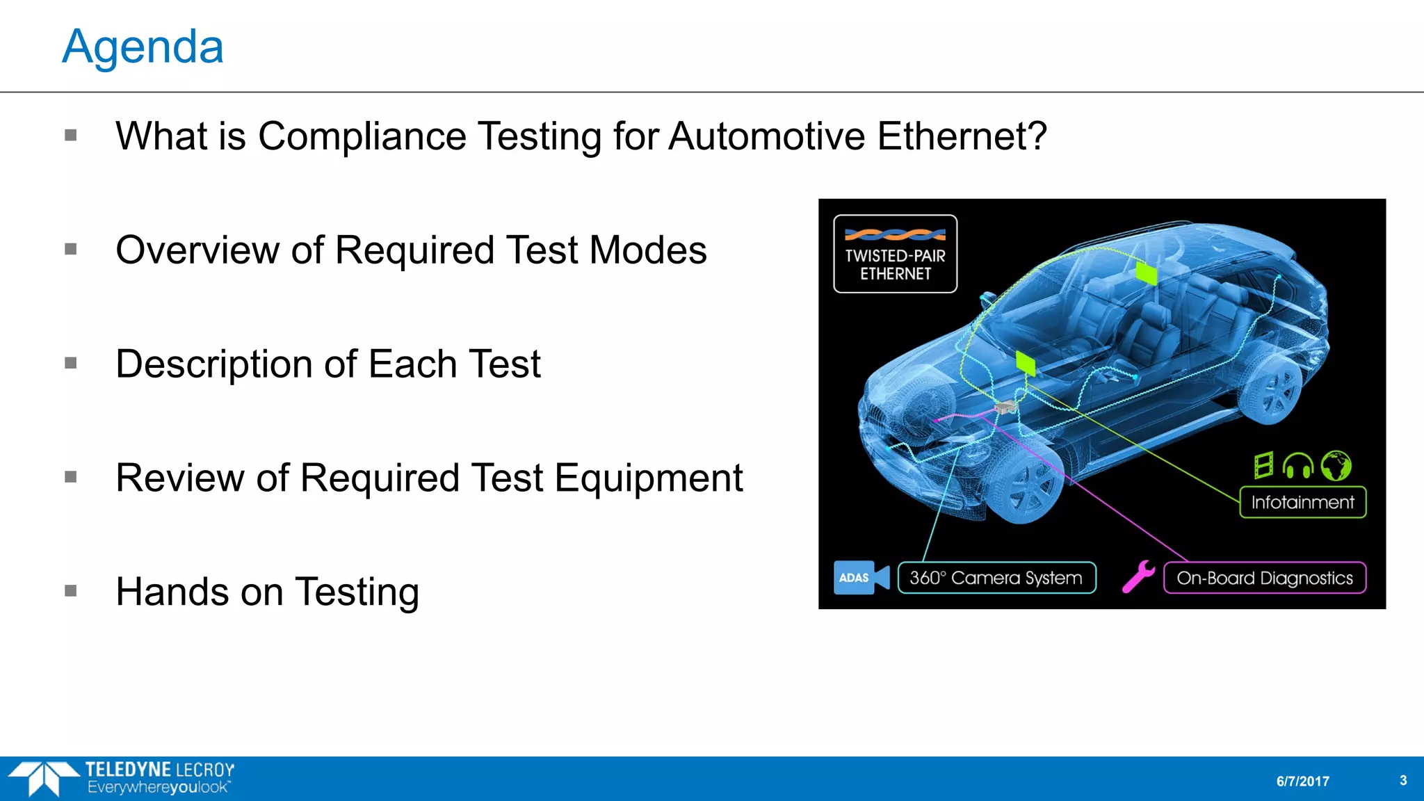
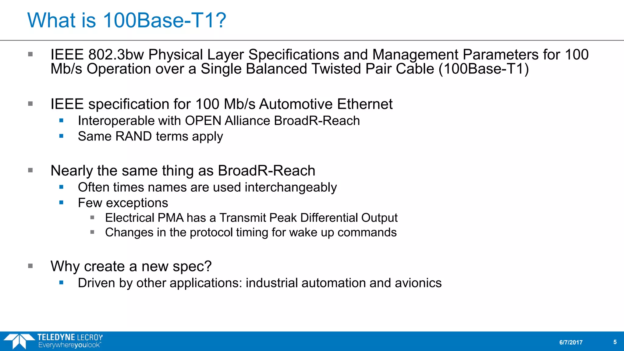
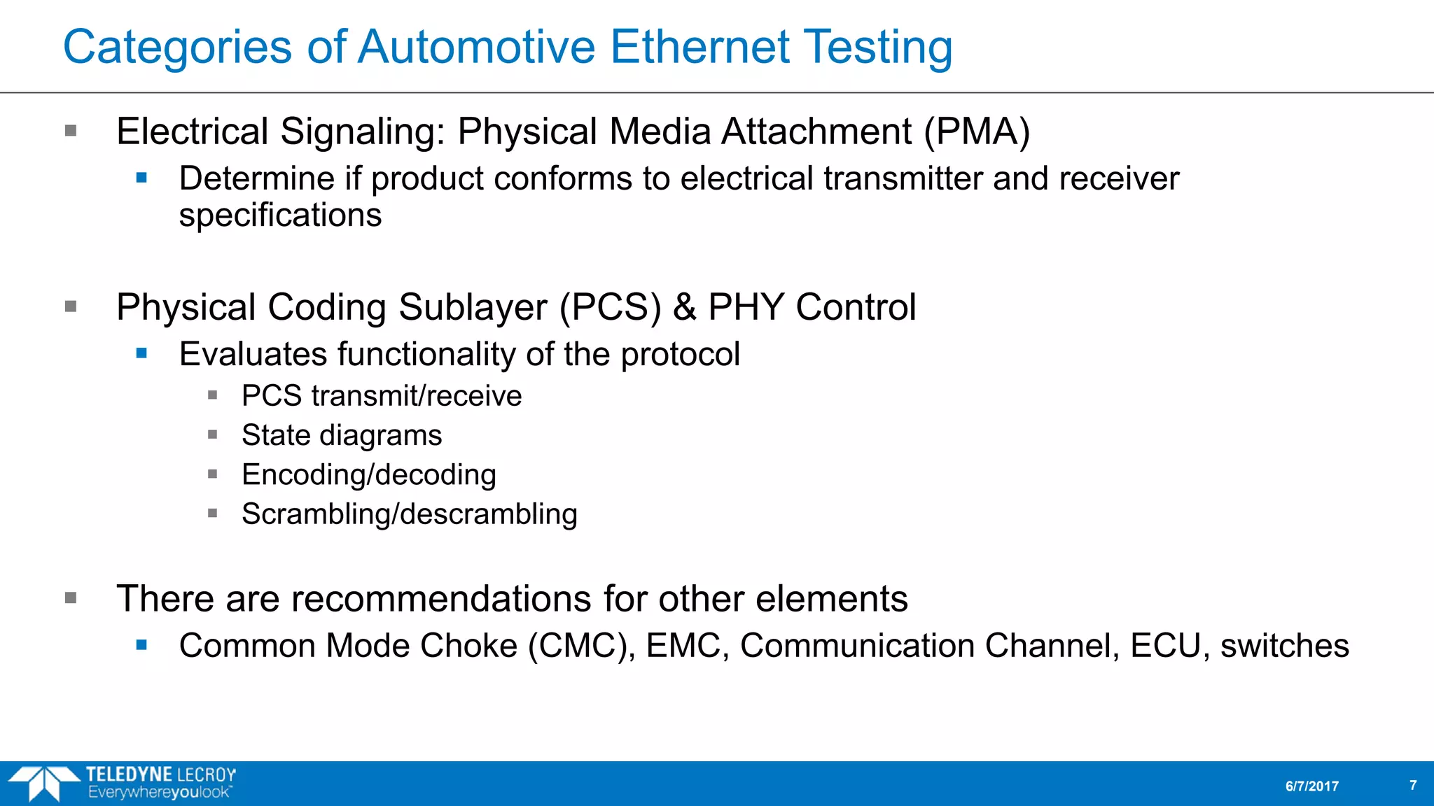
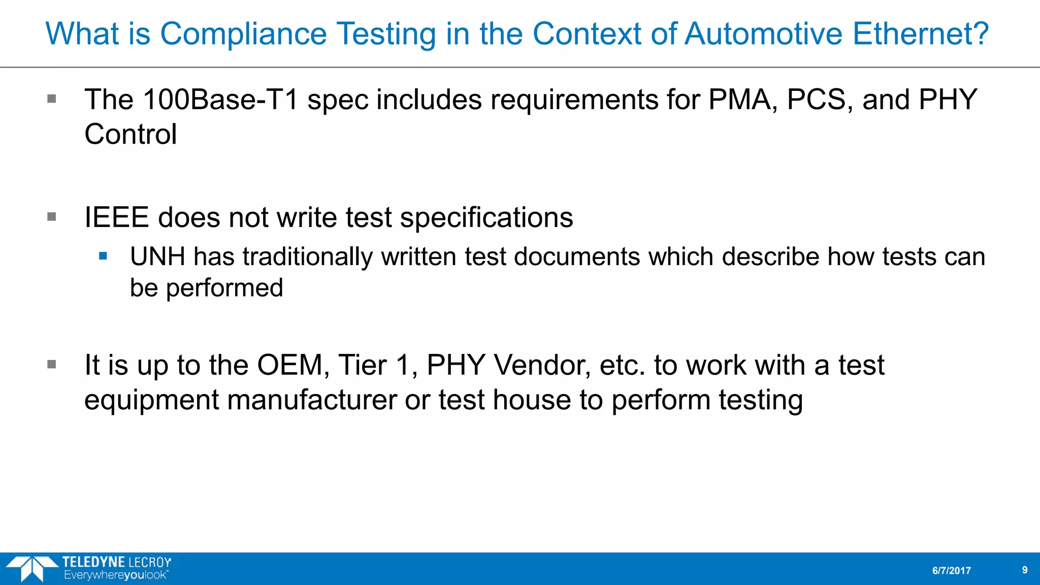
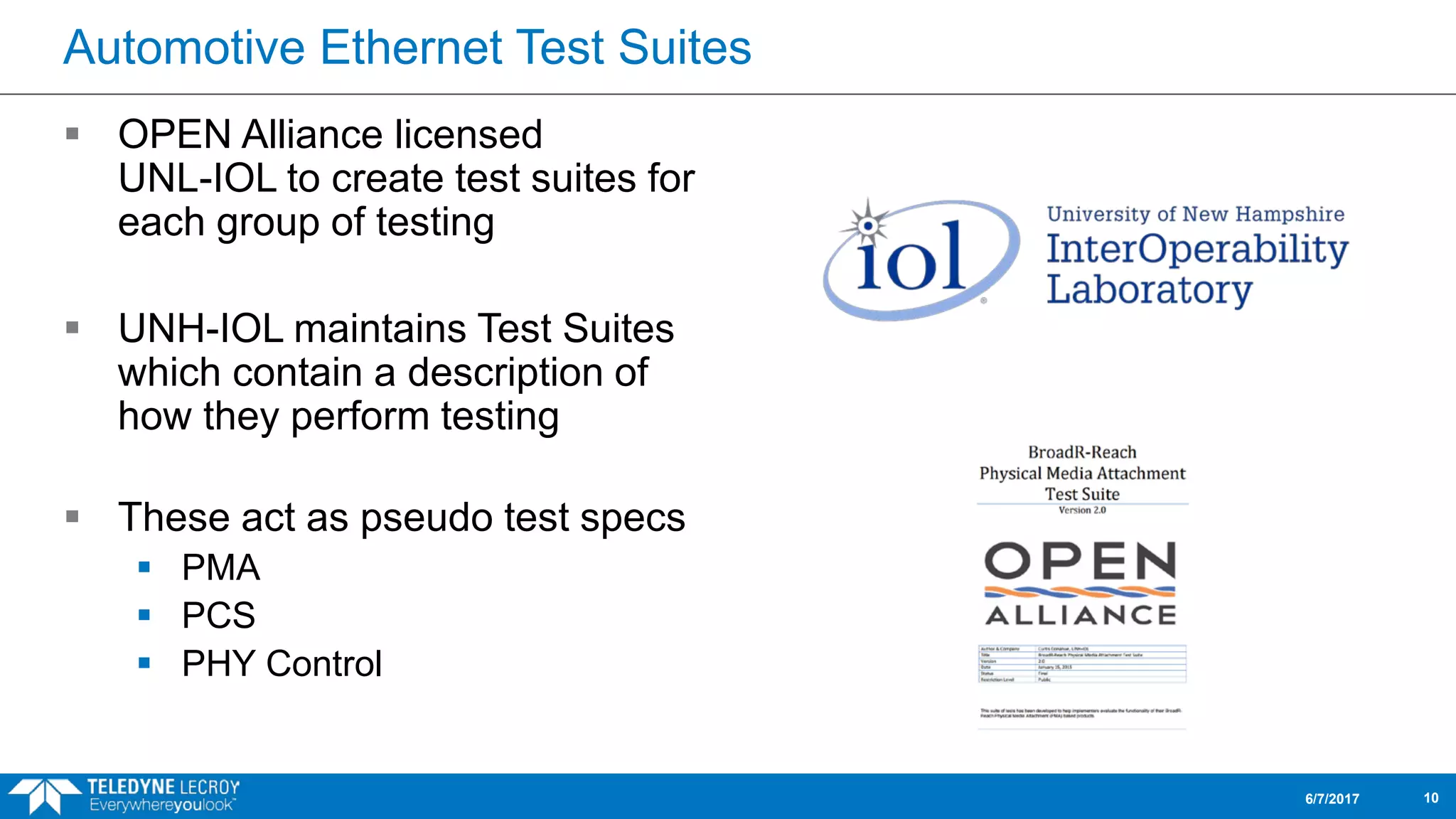
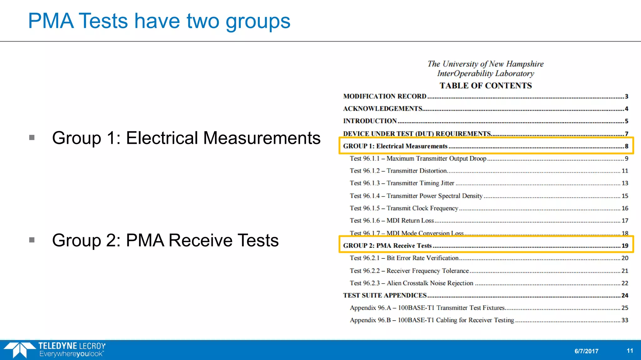
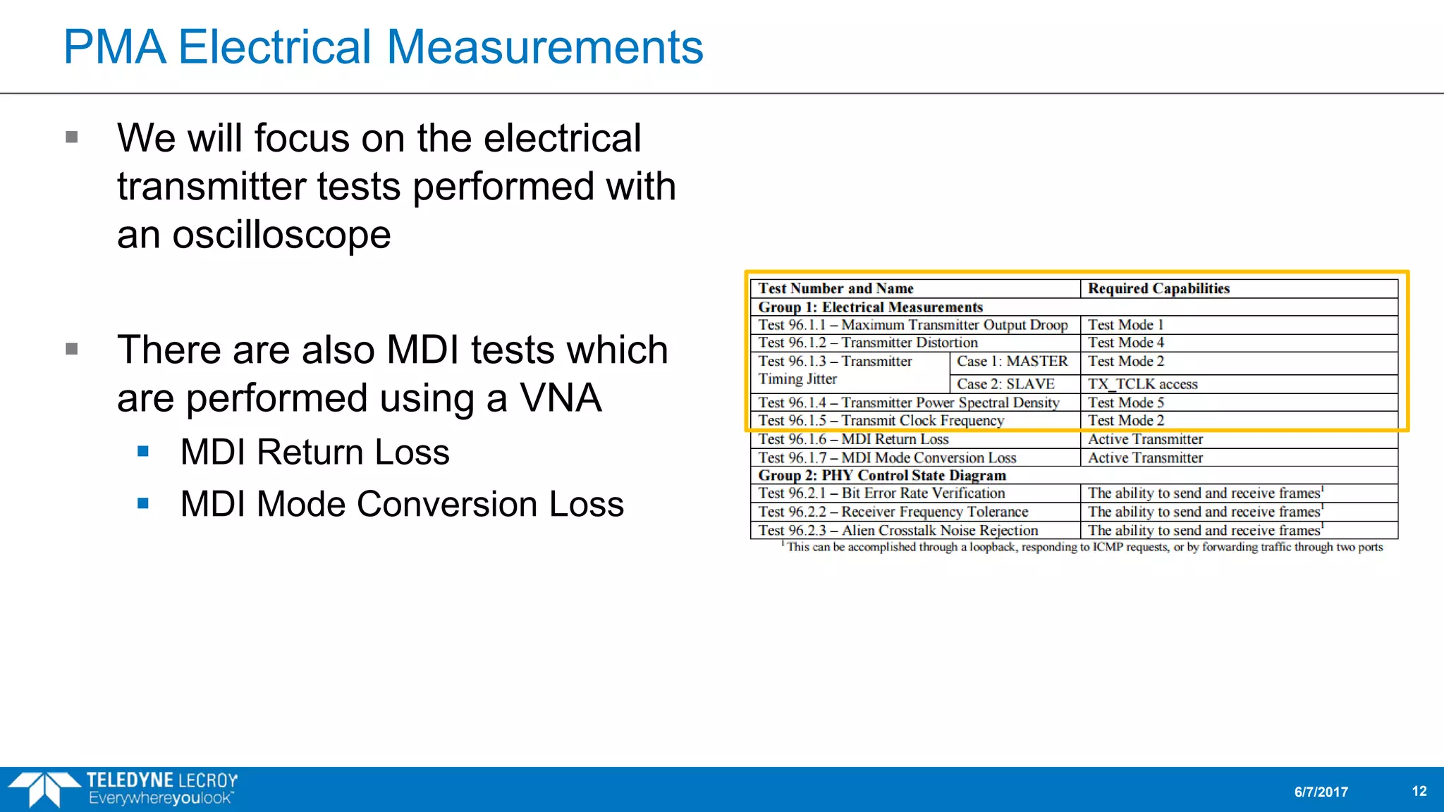
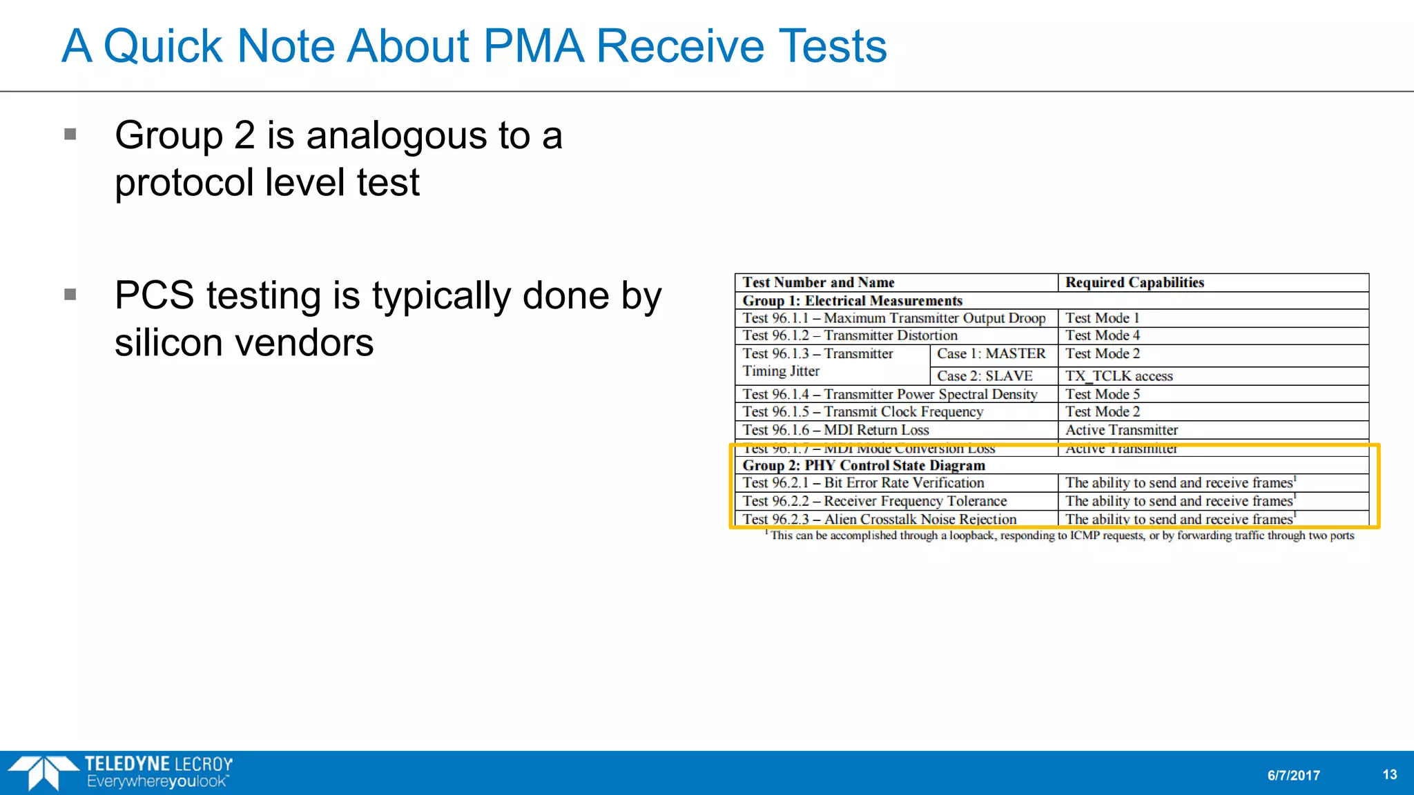
There are numerous design challenges associated with implementing Automotive Ethernet. This session will discuss what to test in order to improve the chances of a successful design
The Basics of Automotive Ethernet Webinar Slidedeckteledynelecroy
Evolving from the BroadR-Reach standard, Automotive Ethernet enables faster data communication to meet the demands of today’s vehicles and the connected vehicles of the future.
This session will focus on the fundamentals of the Automotive Ethernet ecosystem. It will include a brief history and evolution of the standard, and an overview of benefits of the new technology and the associated design challenges. We will conclude with an introduction into the test requirements and the analysis tools available to help troubleshoot and qualify designs.
Getting clocks to agree on the time is tricky. Getting them to agree on the time better than 100 nanoseconds is even trickier.
In this talk I will provide an introduction to the basic principles of the Precision Time Protocol (PTP) and how it can be used to precisely synchronize computers over a LAN.
http://www.nycbug.org/index.cgi?action=view&id=10361
This document discusses real-time operating system (RTOS) concepts. It defines real-time as responsiveness defined by external processes. An RTOS guarantees tasks will finish within time constraints. It explains characteristics like preemptive multitasking, prioritized processes, interrupt handling. The document also covers RTOS scheduling, dispatching, time specifications for tasks and interrupts. Common real-time applications are also listed like military, telecommunications, aviation and more.
The document provides an overview of the UVM configuration database and how it is used to store and access configuration data throughout the verification environment hierarchy. Key points include: the configuration database mirrors the testbench topology; it uses a string-based key system to store and retrieve entries in a hierarchical and scope-controlled manner; and the automatic configuration process retrieves entries during the build phase and configures component fields.
This document discusses VLSI testing and analysis. It defines key terms like defect, fault, and error and describes typical types of defects. It also discusses logical fault models and the role of testing in quality control. Different types of tests like production testing and burn-in testing are described. The testing process, fault simulation, design for testability techniques, and built-in self-test are summarized.
This document discusses CPLDs and the Altera MAX architecture. It describes how CPLDs integrate multiple PALs onto a single chip for more complex logic than a single PAL can provide. It then details the key components of the Altera MAX architecture, including Logic Array Blocks containing macrocells with programmable AND and OR arrays. Logic expanders allow implementing functions requiring more product terms. Programmable inversion can further reduce needed product terms. The MAX 7000 series uses this architecture with additional programmable interconnect and I/O control blocks.
DFT (design for testability) is a technique that facilitates making a design testable after production by adding extra logic during the design process. This extra logic helps with post-production testing. DFT is needed because manufacturing processes are not perfect and can introduce defects. Methods like adding scan chains are used, where scanned flip-flops are connected in series to form a shift register and improve controllability and observability for testing. Common fault models tested for include stuck-at faults, where a line is stuck at either a 0 or 1 value due to defects introduced during manufacturing.
MIPI DevCon 2021: MIPI D-PHY and MIPI CSI-2 for IoT: AI Edge DevicesMIPI Alliance
Presented by Ashraf Takla, Mixel Inc.
This presentation covers the deployment of MIPI D-PHY℠ and MIPI CSI-2® in IoT and edge devices. While many mobile-influenced applications benefit from the low-power, small-form factor of MIPI specifications, AI edge processors in particular are seeing a surge in the use of MIPI specifications for their sensors as market trends shift from processing in the cloud or central location, to processing at the edge.
This presentation includes a high-level system overview of a specific use case, Perceive Ergo edge inference processor, and how Mixel was able to meet Perceive’s stringent requirements with its MIPI D-PHY CSI-2 TX and D-PHY CSI-2 RX IPs.
In telecommunication, an eye pattern, also known as an eye diagram, is an oscilloscope display in which a digital signal from a receiver is repetitively sampled and applied to the vertical input, while the data rate is used to trigger the horizontal sweep. It is so called because, for several types of coding, the pattern looks like a series of eyes between a pair of rails. It is a tool for the evaluation of the combined effects of channel noise and intersymbol interference on the performance of a baseband pulse-transmission system. It is the synchronised superposition of all possible realisations of the signal of interest viewed within a particular signaling interval.
This document provides an overview of an introduction to STM32 course. The course covers the ARM Cortex processor, STM32 system on chip, STM32 building blocks, low power operation, safety features, the flash module, and development tools. The goal of the course is to help students understand what the ARM Cortex processor and STM32 SoC are, and identify the main components of the STM32 microcontroller.
The D-PHY specification, since the release of its first version more than a decade ago, continues to evolve and push the envelope of throughput to support current and future needs of mobile interfaces – camera and display in particular. In this process, PHY layer test and measurement solutions are posed with newer challenges to provide for the feature additions to the specification. This presentation by Parthasarathy Raju and Suryakant Kumar of Tektronix discusses an introduction to both transmitter and receiver characteristics of D-PHY, and highlights the importance of test modes. Also discussed are test/measurement solutions to overcome these challenges and simplify the testing of devices to accomplish conformance.
This document provides an overview of the verification strategy for PCI-Express. It discusses the PCI-Express protocol, including the physical, data link, transaction, and software layers. It outlines the verification paradigm, including functional verification using constrained random testing, assertions, asynchronous/power domain simulations, and performance verification. It also discusses compliance verification through electrical, data link, transaction, and system architecture checklists. Finally, it discusses design for verification through a modular and scalable architecture to promote reusability and reduce verification effort and complexity.
An overview of the communication stack within the classical AUTOSAR
- AUTOSAR Static architecture
- Communication stack
- CAN stack
- PDU-ROUTER
LINKS:
---------
https://www.autosar.org/
This document outlines an agenda for eight sessions on LTE system overview and operation. Session 1 provides an overview of LTE cellular systems, specifications, and network architecture. Sessions 2-8 cover OFDMA and SCFDMA concepts, LTE transmission schemes, protocol architecture, MIMO, UE operations, cell acquisition procedures, handover, and UE testing. The document lists references on LTE system design books and 3GPP specifications.
This document provides an overview of the PCI Express physical layer technology. It discusses the lane counts and data rates supported by different PCIe versions. It describes the three logical layers of PCIe and divides the physical layer into logical and electrical sub-blocks. It explains several key physical layer technologies including 8b/10b encoding, data scrambling, de-emphasis, and link training. Link training negotiates link parameters and ensures synchronization between devices on the link.
The document discusses some of the most commonly used commands in the AMOS LTE command line interface (CLI) for managing and troubleshooting an LTE network. It provides examples of using commands like lt all to load all managed objects, st fdd to check the administrative and operational states of cells, ue print -admitted to check the number of connected users and bearers per cell, get . earfcn to check the E-ARFCN numbers in use for downlink and uplink, and ping to test X2 connectivity between eNodeBs. It also mentions using commands to check power configuration, neighbor lists, license capacity, bandwidth usage, and X2 and S1 connection status.
This document provides a summary of a book about PCI Express technology. It includes an introduction to the book, a table of contents listing the topics covered, biographies of the authors, and endorsements of the book. The summary is as follows:
The document introduces a book that provides a comprehensive guide to PCI Express generations 1.x, 2.x, and 3.0. It includes biographies of the authors and an endorsement quoting that the book is essential for understanding PCI Express. The table of contents indicates it will cover topics such as the origins and architecture of PCI Express, various technical specifications and features, and considerations for high-speed signaling.
The document discusses design for testability (DFT) techniques. It explains that DFT is important for testing integrated circuits due to unavoidable manufacturing defects. DFT aims to increase testability by making internal nodes more controllable and observable. Common DFT techniques mentioned include adding scan chains, which allow testing at speed by launching test vectors from a shift register. Stuck-at fault and transition fault models are discussed as well as methods for detecting these faults including launch-on-capture and launch-on-shift. Fault equivalence and collapsing techniques are also summarized.
UVM is a standardized methodology for verifying complex IP and SOC in the semiconductor industry. UVM is an Accellera standard and developed with support from multiple vendors Aldec, Cadence, Mentor, and Synopsys. UVM 1.0 was released on 28 Feb 2011 which is widely accepted by verification Engineer across the world. UVM has evolved and undergone a series of minor releases, which introduced new features.
UVM provides the standard structure for creating test-bench and UVCs. The following features are provided by UVM
• Separation of tests from test bench
• Transaction-level communication (TLM)
• Sequences
• Factory and configuration
• Message reporting
• End-of-test mechanism
• Register layer
The document discusses amplitude modulation (AM) and different types of AM including double sideband AM (DSBAM), single sideband AM (SSBAM), and their modulation, demodulation, bandwidth requirements, and power considerations. It provides equations, diagrams, and explanations for DSBAM, SSBAM, and synchronous demodulation. Key aspects covered include the carrier signal, message signal, sidebands, modulation depth, spectrum analysis, and transmitter power efficiency comparisons between DSBAM and SSBAM.
The document describes conventions and signals used in the AMBA 3 APB protocol specification version 1.0. It summarizes write and read transfer procedures, including optional wait states using the PREADY signal. Error responses are also described. The operating states of the APB include IDLE, SETUP, and ACCESS states. PREADY controls exiting the ACCESS state.
The document discusses timing closure in FPGA design flows. It explains that timing requirements include clock period/frequency, throughput, and latency. The timing-driven design flow in Lattice Diamond is outlined, highlighting key steps like defining timing constraints, running synthesis and implementation with timing analysis, and iterating to resolve issues. Timing constraints like input/output delays and exceptions are also covered.
PCIe is a standard expansion card interface introduced in 2004 to replace PCI and PCI-X. It uses serial instead of parallel communication and is scalable, allowing for higher maximum system bandwidth. The presentation discusses the history of expansion card standards leading to PCIe, including ISA, EISA, VESA, PCI, and PCI-X. It also covers key aspects of PCIe such as the root complex, endpoints, switches, lanes, bus:device.function notation, enumeration, and address spaces such as configuration space.
The document discusses a two-day training on design for testability using Synopsys' DFT Compiler and TetraMAX tools. Day 1 covers basic DFT concepts and techniques including scan path insertion and memory wrappers using DFT Compiler. Day 2 focuses on TetraMAX for fault simulation, modeling memories, and debugging problems.
The document discusses the building blocks of a SystemVerilog testbench. It describes the program block, which encapsulates test code and allows reading/writing signals and calling module routines. Interface and clocking blocks are used to connect the testbench to the design under test. Assertions, randomization, and other features help create flexible testbenches to verify design correctness.
USB 3.1 Gen 2 Compliance Testing and Debug Webinarteledynelecroy
Join Teledyne LeCroy for this free webinar as we analyze the major changes in the standard compared to its previous versions and offer solutions for compliance testing and debug to help in analysis and characterization of USB 3.1 Gen 2 signals and interfaces.
The document provides an overview of ZigBee/IEEE 802.15.4 wireless technology. It discusses the need for low-power, low-cost wireless connectivity for applications like home automation, medical devices, and industrial sensors. It describes the ZigBee Alliance's role in developing networking and application standards on top of the IEEE 802.15.4 physical radio specification. Key features of ZigBee networks include low power consumption, large network capacity, low data rates, and flexibility for many applications.
This document summarizes the status of the Versatile Link System project. It describes the optical serial data link being developed that aims for data rates of 5Gbps over link lengths of 150 meters. It discusses the system studies conducted including developing test benches and characterizing physical layer performance. It also outlines the generation of a system level specification detailing parameters such as optical power levels, jitter, and link budgets for both multi-mode and single-mode variants of the system.
Michael Monaghan - Evolution of New Feature Verification in 3G NetworksTEST Huddle
EuroSTAR Software Testing Conference 2009 presentation on Evolution of New Feature Verification in 3G Networks by Michael Monaghan. See more at conferences.eurostarsoftwaretesting.com/past-presentations/
Proposal for Wireleess Throughput Test by Automation Richard Hsu
This proposal outlines automating wireless throughput testing to decrease manpower needs, increase testing coverage, and shorten time to market. Originally the testing required 2-3 engineers and could only test a few wireless modes and channels without encryption. The automated process allows one engineer to run more complex test matrices including different wireless modes, channels, encryptions, distances, angles, and device positions. This improves the testing flow and allows engineers to test more easily and quickly.
PAM4 Analysis and Measurement Considerations WebinarHilary Lustig
This webinar explores the acquisition and analysis of PAM4 waveforms. We will show PAM4 Test Configurations, Compliance Measurements and Debug Techniques.
PAM4 Analysis and Measurement Webinar Slidedeckteledynelecroy
In this Teledyne LeCroy webinar we explore the acquisition and analysis of PAM4 waveforms. We will cover PAM4 test configurations, compliance measurements and debug techniques.
This document provides an overview of tests for installing and maintaining LTE eNodeB base stations. It describes the key tests to check characteristics like downlink and uplink speeds, channel bandwidths, frequency bands, frame structure, and modulation schemes. The document then explains specific tests to check aspects like transmission power, occupied bandwidth, spectrum emission mask, ACLR, spurious emissions, and modulation quality of control and data channels. It provides procedures for configuring a tester and interpreting results for each test.
Range to Fault for PIM Testing (Kaelus white paper)Kaelus
Range to Fault (RTF) technology is a new analysis tool that uses signal processing to determine the location of passive intermodulation (PIM) sources on cellular infrastructure. RTF works by transmitting test signals and analyzing the resulting intermodulation products to estimate fault locations. It provides a starting point but still requires dynamic PIM testing for certification. An example demonstrates RTF accurately locating multiple static PIM sources and improving results as each is repaired, though a dynamic test still found an additional problem. RTF analysis enhances testing efficiency but does not replace the need for dynamic PIM verification.
Field testing of mobile devices involves:
- Testing the device's interoperability with live public networks to ensure robust performance and minimize returns.
- A development cycle that includes field testing where the device is connected to a live network under real conditions to identify software quality issues and customer experience.
- Testing features such as call quality, roaming, handover, signal strength, and data performance under different conditions such as urban, suburban, and moving environments.
The document compares different types of testers used for debugging components, including S9K, IMS Vanguard, and CWMA testers, describing their key features such as speed, operating system, memory size, and capabilities for timing, patterns, and levels of testing. It also provides overviews of tester channel connections, functional test content and tools, and terms and definitions used for testing.
The document discusses LTE-Advanced conformance and standards. It provides an overview of the LTE conformance ecosystem including 3GPP specifications, validation of test platforms and cases, and certification by bodies like GCF and PTCRB. It then gives a status update on LTE-Advanced, describing features like carrier aggregation and their role in achieving IMT-Advanced requirements. Key aspects covered are 3GPP status, certification, and the use of carrier aggregation to deliver higher data rates up to 3 Gbps.
Operator E CA(Carrier Aggregation) Feature Test Guide.docxAkhtar Khan
This document provides a test guide for carrier aggregation (CA) features on Operator E's LTE network. It describes introducing multiple component carriers to expand bandwidth up to 100MHz. The test uses three carriers in different bands to test downlink carrier aggregation of up to 60MHz. Key steps included configuring the core network to allow high bandwidth, setting up the radio network for contiguous and non-contiguous carriers, verifying UE capabilities, and monitoring throughput results. Testing showed throughput increases with CA and supported band combinations depending on the UE model.
This document discusses hardware design verification and testing techniques. It covers emulation architectures like FPGA-based and processor-based systems. It also discusses formal property verification methods, software formal verification, design for test objectives, chip-level DFT techniques, automatic test pattern generation, and testing techniques for analog/mixed-signal circuits like ADCs, PLLs and oscillators.
Essential quality criteria for planning and validation of PROFINET networks
For PROFINET devices the quality criteria that are checked within the scope of the device certification are described in published specifications, standards and test specifications. Interoperability is protected by both the specification and the test procedures in the cooperation of the devices. From practical experience in the realization of network arrangements it appears that beside the device qualities also the planning quality and the quality of the validation of a whole arrangement can have an influence on the functionality.
In the task force CB / PG3 "Installation Guidelines" the suitable planning directives and introduction directives are now integrated into the quality criteria for the planning and validation of the PROFINET networks. The methods, measuring procedures and also the background will be fully explained.
The document discusses optimization of 3G radio networks, focusing on the RF Optimization phase. It describes the various stages of network optimization including single site verification, RF optimization of clusters of sites, parameter optimization testing, and ongoing reference route testing and analysis. The RF Optimization process involves preparing clusters and drive routes, analyzing data to identify issues, determining solutions such as antenna adjustments, implementing changes, and retesting. Analysis approaches discussed include examining cell dominance, coverage, interference, uplink coverage, pilot pollution, neighbor lists, soft handover performance, and drop calls.
This document discusses key factors impacting LTE network performance including expected performance metrics, dependencies, and challenges. It provides an overview of call setup times and throughputs expected under ideal conditions, then discusses how factors like deployment issues, RF interference, backhaul limitations, scheduler configuration, and mobility parameters can negatively influence performance and result in increased call setup times, lower throughputs, and handover failures. The document aims to help network operators identify areas to focus on for optimizing LTE network performance at launch.
STS Characterization to Production TestHank Lydick
The document discusses bridging the gap between RF front-end module characterization and production testing. It describes how NI's semiconductor test system (STS) uses a common PXI hardware and software platform to allow characterization and production teams to use the same instrumentation and share test data, reducing time to market. The STS integrates RF and non-RF instruments into an enclosed test head and supports various wireless standards and RF measurements.
Drive Test and Optimization Tutorial - I.pdfhamdi_saif
The document discusses drive testing procedures and measurements. It describes the required tools for drive testing including a laptop, GPS device, and test software. It outlines key radio parameters measured for 2G, 3G, and 4G networks including signal strength, quality, interference, and throughput. Examples of drive test activities are given such as new site acceptance tests involving calls, SMS, and internet usage to check coverage and quality.
Similar to Automotive Ethernet: Physical Layer Compliance Testing Webinar Slides (20)
Webinar: High Voltage Fiber Optic (HVFO) Probe for Small Signal Floating Meas...teledynelecroy
Join Teledyne LeCroy for this webinar as we provide an overview of the differences between a conventional high-attenuation HV differential probe, a HV isolated oscilloscope input, and the HVFO, along with some real-world measurement examples.
Webinar: Practical DDR Testing for Compliance, Validation and Debugteledynelecroy
Join Teledyne LeCroy for this free webinar as we first cover the basics of a DDR interface with a focus on physical-layer test challenges and solutions to common problems. We will then outline the general procedures and considerations for compliance, debug and validation test scenarios. Finally, case studies will illustrate how to apply sophisticated test tools to solve real-life problems.
Webinar Slides: Measurements and Analysis for Switched-mode Power Designsteledynelecroy
This webinar covers the measurements of interest for designers of switched-mode power conversion circuits and devices. With the goal of high efficient and reliable designs, we review the acquisition of voltage and current, their relationship in switched-mode power conversion circuits.
We review specific power circuit performance areas including the analysis of power device switching losses, conduction losses, dynamic on-resistance, control loop response, power quality, conducted emissions, best practices for probing power circuits, and power rail integrity measurements.
Webinar Slides: Probing Techniques and Tradeoffs – What to Use and Whyteledynelecroy
Engineers must commonly probe low and high frequency signals with high signal fidelity. Typical passive probes with high input impedance and capacitance provide good response at lower frequencies, but inappropriately load the circuit and distort signals at higher frequencies.
Join Teledyne LeCroy for this webinar as we discuss:
- Selecting the right probing techniques to maximize the accuracy of your measurements
- Probe specifications and their implications on the measured signal
- Variety of probes and accessories available for measurement
- Virtual probing software tools that allow the user to probe the signal when direct access is physically impossible
Webinar Slides: Digital Power Management and Power Integrity Analysis and Tes...teledynelecroy
Join Teledyne LeCroy for an overview of digital power management, power integrity, and power sequencing. We'll discuss test of single or multi-phase digital power management ICs (PMICs), voltage regulator modules (VRMs), point-of-load (POLs) switching regulators, low-dropout (LDO) regulators or other DC-DC converter operations under transient load conditions, and test of complete embedded systems that contain these devices.
Webinar Slides: Probing in Power Electronics - What to use and whyteledynelecroy
Join Teledyne LeCroy for this webinar as we provide an overview of the different HV rated probe specifications and topologies, explain what measurement each probe topology is ideally suited for, and provide real-word examples and comparisons between a variety of different probes and amplifiers.
Join Teledyne LeCroy for a discussion of what S-parameters are and why we should care about them. As serial data rates move into the multi-gigabit domain, S-parameters play an important role in understanding system performance. We will uncover the four main patterns found in s-parameters and learn what they can tell us about our interconnects.
Nov 12 Webcast: Eliminate Pitfalls of DDR Memory Testing
Join Teledyne LeCroy's, Mike Hertz, for this free webinar on using an oscilloscope for validation and debug of DDR2/3/4 physical layer measurements.
Topics covered will include: probing, connectivity, recommended device patterns, de-embedding, examples of good and bad waveforms, and debugging steps and techniques.
Mike Hertz has been a Field Applications Engineer with Teledyne LeCroy in Michigan for 14 years.
October 8, 2014 Webcast Identifying PCI Express 3.0 Dynamic Equalization Problems
Dynamic equalization training is a unique capability in modern day serial data communication. Through optimization of transmitter and receiver equalization parameters we can push the limits of serial data rates. Troubleshooting dynamic equalization problems at the Physical and Protocol layers requires testing for proper functionality and compliance.
Join Teledyne LeCroy's Stephen Mueller for this webinar to understand how to address this measurement challenge. The presentation will include real measurement examples and debugging techniques to pinpoint problems in the physical and protocol layers.
Essentials of jitter part 1 The Time Interval Error: TIEteledynelecroy
This document discusses jitter and its measurement. Jitter is measured as the time interval error (TIE) between the actual and expected arrival times of signal edges. TIE values over time form the TIE track waveform, which can be analyzed statistically, in the frequency domain, and through histograms to identify different jitter sources. Proper jitter measurement requires determining the expected edge times, which may involve clock data recovery for signals without a reference clock.
Essentials of jitter part 3 webinar slidesteledynelecroy
In this final part, we will explore how we measure and analyze jitter in high speed serial links.
We will look at how to take a measurement on less than a million bits and extrapolate the total jitter to a million times as many bits and when we need to find the root cause of jitter, how to decompose the total jitter into its five components.
Using and OMA to Optimize QAM Optical Transceiversteledynelecroy
This webinar demonstrated the optimization of a 28GBaud DP-16QAM modulated optical signal using an optical modulation analyzer. The presentation reviewed the system setup including electrical PAM4 signal generation, coherent optical transmission, and signal analysis using digital signal processing. Live demonstrations showed tuning the electrical PAM4 signals, optimizing the optical transmitter bias points and skew, and adjusting the signal levels for best performance. The goal was to maximize signal integrity for 16QAM optical transmission.
Essential principles of jitter part 2 the components of jitterteledynelecroy
-The power of statistical analysis
-The five fundamental types of jitter: ISI, DCD, Periodic, Random, Other
-Their statistical “signature”
-The jitter “tree”
-Synthesizing examples based on their root cause
Comparative analysis between traditional aquaponics and reconstructed aquapon...bijceesjournal
The aquaponic system of planting is a method that does not require soil usage. It is a method that only needs water, fish, lava rocks (a substitute for soil), and plants. Aquaponic systems are sustainable and environmentally friendly. Its use not only helps to plant in small spaces but also helps reduce artificial chemical use and minimizes excess water use, as aquaponics consumes 90% less water than soil-based gardening. The study applied a descriptive and experimental design to assess and compare conventional and reconstructed aquaponic methods for reproducing tomatoes. The researchers created an observation checklist to determine the significant factors of the study. The study aims to determine the significant difference between traditional aquaponics and reconstructed aquaponics systems propagating tomatoes in terms of height, weight, girth, and number of fruits. The reconstructed aquaponics system’s higher growth yield results in a much more nourished crop than the traditional aquaponics system. It is superior in its number of fruits, height, weight, and girth measurement. Moreover, the reconstructed aquaponics system is proven to eliminate all the hindrances present in the traditional aquaponics system, which are overcrowding of fish, algae growth, pest problems, contaminated water, and dead fish.
Advanced control scheme of doubly fed induction generator for wind turbine us...IJECEIAES
This paper describes a speed control device for generating electrical energy on an electricity network based on the doubly fed induction generator (DFIG) used for wind power conversion systems. At first, a double-fed induction generator model was constructed. A control law is formulated to govern the flow of energy between the stator of a DFIG and the energy network using three types of controllers: proportional integral (PI), sliding mode controller (SMC) and second order sliding mode controller (SOSMC). Their different results in terms of power reference tracking, reaction to unexpected speed fluctuations, sensitivity to perturbations, and resilience against machine parameter alterations are compared. MATLAB/Simulink was used to conduct the simulations for the preceding study. Multiple simulations have shown very satisfying results, and the investigations demonstrate the efficacy and power-enhancing capabilities of the suggested control system.
A review on techniques and modelling methodologies used for checking electrom...nooriasukmaningtyas
The proper function of the integrated circuit (IC) in an inhibiting electromagnetic environment has always been a serious concern throughout the decades of revolution in the world of electronics, from disjunct devices to today’s integrated circuit technology, where billions of transistors are combined on a single chip. The automotive industry and smart vehicles in particular, are confronting design issues such as being prone to electromagnetic interference (EMI). Electronic control devices calculate incorrect outputs because of EMI and sensors give misleading values which can prove fatal in case of automotives. In this paper, the authors have non exhaustively tried to review research work concerned with the investigation of EMI in ICs and prediction of this EMI using various modelling methodologies and measurement setups.
ACEP Magazine edition 4th launched on 05.06.2024Rahul
This document provides information about the third edition of the magazine "Sthapatya" published by the Association of Civil Engineers (Practicing) Aurangabad. It includes messages from current and past presidents of ACEP, memories and photos from past ACEP events, information on life time achievement awards given by ACEP, and a technical article on concrete maintenance, repairs and strengthening. The document highlights activities of ACEP and provides a technical educational article for members.
Using recycled concrete aggregates (RCA) for pavements is crucial to achieving sustainability. Implementing RCA for new pavement can minimize carbon footprint, conserve natural resources, reduce harmful emissions, and lower life cycle costs. Compared to natural aggregate (NA), RCA pavement has fewer comprehensive studies and sustainability assessments.
Understanding Inductive Bias in Machine LearningSUTEJAS
This presentation explores the concept of inductive bias in machine learning. It explains how algorithms come with built-in assumptions and preferences that guide the learning process. You'll learn about the different types of inductive bias and how they can impact the performance and generalizability of machine learning models.
The presentation also covers the positive and negative aspects of inductive bias, along with strategies for mitigating potential drawbacks. We'll explore examples of how bias manifests in algorithms like neural networks and decision trees.
By understanding inductive bias, you can gain valuable insights into how machine learning models work and make informed decisions when building and deploying them.
Literature Review Basics and Understanding Reference Management.pptxDr Ramhari Poudyal
Three-day training on academic research focuses on analytical tools at United Technical College, supported by the University Grant Commission, Nepal. 24-26 May 2024
Using recycled concrete aggregates (RCA) for pavements is crucial to achieving sustainability. Implementing RCA for new pavement can minimize carbon footprint, conserve natural resources, reduce harmful emissions, and lower life cycle costs. Compared to natural aggregate (NA), RCA pavement has fewer comprehensive studies and sustainability assessments.
Harnessing WebAssembly for Real-time Stateless Streaming PipelinesChristina Lin
Traditionally, dealing with real-time data pipelines has involved significant overhead, even for straightforward tasks like data transformation or masking. However, in this talk, we’ll venture into the dynamic realm of WebAssembly (WASM) and discover how it can revolutionize the creation of stateless streaming pipelines within a Kafka (Redpanda) broker. These pipelines are adept at managing low-latency, high-data-volume scenarios.
CHINA’S GEO-ECONOMIC OUTREACH IN CENTRAL ASIAN COUNTRIES AND FUTURE PROSPECTjpsjournal1
The rivalry between prominent international actors for dominance over Central Asia's hydrocarbon
reserves and the ancient silk trade route, along with China's diplomatic endeavours in the area, has been
referred to as the "New Great Game." This research centres on the power struggle, considering
geopolitical, geostrategic, and geoeconomic variables. Topics including trade, political hegemony, oil
politics, and conventional and nontraditional security are all explored and explained by the researcher.
Using Mackinder's Heartland, Spykman Rimland, and Hegemonic Stability theories, examines China's role
in Central Asia. This study adheres to the empirical epistemological method and has taken care of
objectivity. This study analyze primary and secondary research documents critically to elaborate role of
china’s geo economic outreach in central Asian countries and its future prospect. China is thriving in trade,
pipeline politics, and winning states, according to this study, thanks to important instruments like the
Shanghai Cooperation Organisation and the Belt and Road Economic Initiative. According to this study,
China is seeing significant success in commerce, pipeline politics, and gaining influence on other
governments. This success may be attributed to the effective utilisation of key tools such as the Shanghai
Cooperation Organisation and the Belt and Road Economic Initiative.
2. Upcoming Events: teledynelecroy.com/events
Live Seminar: Automotive Ethernet Day
Basics Of Automotive Ethernet and Physical Compliance
Santa Clara, CA
Live Seminar: Automotive Ethernet Day
Basics Of Automotive Ethernet and Physical Compliance
Farmington Hills, MI
3. Agenda
What is Compliance Testing for Automotive Ethernet?
Overview of Required Test Modes
Description of Each Test
Review of Required Test Equipment
Hands on Testing
6/7/2017 3
4. Defining Automotive Ethernet
Can refer to any Ethernet-based
network for in-vehicle electrical
systems
Enables faster data
communication to meet rising
demand
Specifically tailored to meet the
needs of automotive industry
6/7/2017 4
BroadR-Reach
Automotive Ethernet
100Base-T1
1000Base-T1
OABR
(OPEN Alliance
BroadR-Reach)
RTPGE
(Reduced Twisted
Pair Gigabit
Ethernet)
5. What is 100Base-T1?
IEEE 802.3bw Physical Layer Specifications and Management Parameters for 100
Mb/s Operation over a Single Balanced Twisted Pair Cable (100Base-T1)
IEEE specification for 100 Mb/s Automotive Ethernet
Interoperable with OPEN Alliance BroadR-Reach
Same RAND terms apply
Nearly the same thing as BroadR-Reach
Often times names are used interchangeably
Few exceptions
Electrical PMA has a Transmit Peak Differential Output
Changes in the protocol timing for wake up commands
Why create a new spec?
Driven by other applications: industrial automation and avionics
6/7/2017 5
7. Categories of Automotive Ethernet Testing
Electrical Signaling: Physical Media Attachment (PMA)
Determine if product conforms to electrical transmitter and receiver
specifications
Physical Coding Sublayer (PCS) & PHY Control
Evaluates functionality of the protocol
PCS transmit/receive
State diagrams
Encoding/decoding
Scrambling/descrambling
There are recommendations for other elements
Common Mode Choke (CMC), EMC, Communication Channel, ECU, switches
6/7/2017 7
8. We will focus on Electrical Signaling
Electrical Signaling: Physical Media Attachment (PMA)
Determine if product conforms to electrical transmitter and receiver
specifications
Physical Coding Sublayer (PCS) & PHY Control
Evaluates functionality of the protocol
PCS transmit/receive
State diagrams
Encoding/decoding
Scrambling/descrambling
There are recommendations for other elements
Common Mode Choke (CMC), EMC, Communication Channel, ECU, switches
6/7/2017 8
9. What is Compliance Testing in the Context of Automotive Ethernet?
The 100Base-T1 spec includes requirements for PMA, PCS, and PHY
Control
IEEE does not write test specifications
UNH has traditionally written test documents which describe how tests can
be performed
It is up to the OEM, Tier 1, PHY Vendor, etc. to work with a test
equipment manufacturer or test house to perform testing
6/7/2017 9
10. Automotive Ethernet Test Suites
OPEN Alliance licensed
UNL-IOL to create test suites for
each group of testing
UNH-IOL maintains Test Suites
which contain a description of
how they perform testing
These act as pseudo test specs
PMA
PCS
PHY Control
6/7/2017 10
11. PMA Tests have two groups
Group 1: Electrical Measurements
Group 2: PMA Receive Tests
6/7/2017 11
12. PMA Electrical Measurements
We will focus on the electrical
transmitter tests performed with
an oscilloscope
There are also MDI tests which
are performed using a VNA
MDI Return Loss
MDI Mode Conversion Loss
6/7/2017 12
13. A Quick Note About PMA Receive Tests
Group 2 is analogous to a
protocol level test
PCS testing is typically done by
silicon vendors
6/7/2017 13
14. Why is PHY Compliance Important?
OEMs have a lengthy development cycle for an ECU
Need assurance that PHY chip meets requirements prior to implementation
Once the PHY chip has been incorporated into the ECU it should also
be tested – testing is not just for PHY vendors
This may be full compliance testing or a subset of compliance tests
Compliance to 100BASE-T1 does not guarantee interoperability
Transmitter requirements are well defined, the receiver is left up to the
implementer
6/7/2017 14
15. Where is the Electrical Compliance Testing Defined?
6/7/2017 15
Defined at the connector of the transmitter
Governed by channel/connector recommendations
17. 100Base-T1 has 5 Test Modes
Why do we have test modes?
Allow for a common pattern to test stressful conditions across all devices
Improves odds of interoperability
Based off of IEEE 802.3 Clause 40.6.1.1.2
6/7/2017 17
Test Modes Tests Performed
Test Mode 1 Output Droop
Test Mode 2 Master Jitter & Clock Frequency
Test Mode 3 (optional) Slave Jitter
Test Mode 4 Distortion
Test Mode 5 Power Spectral Density & Peak Differential Output
18. Test Mode 1 – Transmit Droop
6/7/2017 18
N “+1” symbols followed by N “-1” symbols
ie: square wave
N symbol period must be greater than 500 ns
N > 34 symbols
19. Test Mode 2 – Transmit Jitter in Master Mode
6/7/2017 19
33 1/3 MHz clock
Repeating sequence of {-1,1}
20. Test Mode 3 – Transmit Jitter in Slave Mode (optional)
6/7/2017 20
33 1/3 MHz clock – timed in Slave mode
Repeating sequence of {-1,1}
21. Test Mode 4 – Transmitter Distortion Test
6/7/2017 21
PAM-3 signal with a symbol interval of 15 ns
Repeating pattern every 2047 symbols
g(x) = 1 + x9 + x11
22. Test Mode 5 – Normal Operation at Full Power
6/7/2017 22
PAM-3 symbol with a symbol interval of 15 ns
Random sequence of {-1,0,1}
23. Generation of Test Modes
Each PHY vendor has a “backdoor” method to modify the necessary
registers to enter each test mode
This often not publically available and the method will vary from vendor
to vendor
You must ask your PHY vendor how to generate these test modes
6/7/2017 23
25. 7 Differential Electrical Physical Layer Compliance Tests
BroadR-Reach & 100Base-T1
Maximum Transmitter Output Droop
Transmitter Clock Frequency
Transmitter Timing Master Jitter
Transmitter Timing Slave Jitter
Transmitter Distortion
Transmitter Power Spectral Density (PSD)
100Base-T1 Only
Transmitter Peak Differential Output
6/7/2017 25
26. Test Setup for PMA Compliance Testing
6/7/2017 26
Oscilloscope
DUT
“Short” Automotive Ethernet CableEthernet Test Fixture
27. Close up of Test Setup for PMA Compliance Testing
6/7/2017 27
DUT
Pair A
Differential
Signal
SMA Cables to
oscilloscope RJ45 Breakout Section
28. Maximum Transmitter Output Droop – Description
Test Mode 1
Measure positive and negative
droop
Test limit is 45%
Verify that the transmitter does
not droop more than the
specified amount
6/7/2017 28
Source: IEEE 100Base-T1 Figure 96-23
29. Maximum Transmitter Output Droop – Methodology
6/7/2017 29
1. Locate Initial Peak
(Vpk+ & Vpk-)
2. Measure Voltage after 500 ns
(Vdrooped+ & Vdrooped-)
30. Maximum Transmitter Output Droop – Methodology
6/7/2017 30
3. Calculate Droop+ & Droop-
Droop = 100 x (Vdrooped/Vpk)
4. Compare to
limit of 45%
31. Transmitter Clock Frequency – Description
Test Mode 2
Measure symbol transmission rate in Master Mode
Test limit is 66 2/3 MBd +/- 100 ppm
Verify that the frequency of the transmitted clock meets the spec limits
6/7/2017 31
33. Transmitter Clock Frequency – Methodology
6/7/2017 33
2. Compare to limit Note: 33 MHz
is half the baud
rate, since it
takes two
symbols to
create one
cycle
34. Transmitter Timing Master Jitter – Description
Test Mode 2
Measure RMS (root mean squared) of the MDI output jitter over at least
1 ms
Test limit is 50 ps
This test will verify that the jitter on the transmitted clock is within the
specified limits
6/7/2017 34
37. What is a track?
6/7/2017 37
A plot of each measured value in an acquisition
In this case there are 13 measured values
1
2
3
4
5
6
7
8
9
10
11
12
13
Provides insight into temporal trends of measured data
38. Transmitter Timing Master Jitter – Methodology
6/7/2017 38
3. Measure rms of TIE track
4. Compare to 50 ps
39. Transmitter Timing Slave Jitter – Description
In normal operation as Slave
Probe TX_TCLK or Test mode 3
Measure RMS (root mean
squared) jitter of Slave TX_TCLK
Test limit is 0.01 UI (150 ps)
This test will verify that the jitter
on the signals received by the
slave is within the specified limits
6/7/2017 39
Source: IEEE 100Base-T1 Figure 96-24
40. Access to TX_TCLK
6/7/2017 40
TX_TCLK = transmitted clock
The spec says that each DUT must provide a means to access this
clock
Rarely the case unless testing a PHY eval board
ie: ECU
Without access to the TX_TCLK this test cannot be performed
Source: IEEE 100Base-T1
41. Transmitter Timing Slave Jitter – Methodology
6/7/2017 41
3. Measure rms of TIE track
4. Compare to 150 ps 1. Measure TIE
2. Create a track of TIE measurements
42. Transmitter Distortion – Description
Test mode 4
Requires access to the TX_TCLK
A disturbing sine wave is sent to
DUT and distortion is measured
Test limit is 15 mV
Make sure the transmitted signal
has minimal distortion so the link
partner's receiver can
interoperate with the DUT
6/7/2017 42
Source: IEEE 100Base-T1 Figure 96-21
43. Setup for Disturbing Sine Wave (Vd)
Simulates the presence of a remote
transmitter
If the DUT is not sufficiently linear Vd
will cause significant distortion
products to appear in the DUT output
Frequency must be exactly 1/6 of the
DUTs symbol rate
DUT must be subjected to Vd of
5.4 Vpk-pk
Test can be performed with or without
Vd
6/7/2017 43
44. Matlab Code is Provided in the Spec for Peak Distortion Calculation
Any error from ideal reference is
counted as distortion
Removes the disturbing sine
wave and measures peak
distortion at equally spaced
phases of the symbol period
Can be run on a separate PC
Teledyne LeCroy embeds Matlab
code in the scope software
Doesn’t require a Matlab license
to process
6/7/2017 44
Source: IEEE 100Base-T1
45. The Distortion Test Setup is Very Complicated
Disturbing sinewave source,
oscilloscope, and DUT all need
to locked in frequency
DUT has a reference clock of
66 2/3 MHz
All test equipment takes a
reference clock in of 10 MHz
6/7/2017 45
46. Software Clock Recovery – Distortion Testing Made Easy
Teledyne LeCroy has developed a unique software clock recovery
algorithm
First demonstrated at UNH Plugfest in November 2016
Removes the need to synchronize the DUT with the scope and
disturbing sine wave
Enables test to be completed without a hardware frequency converter
board
Makes setup simpler and cheaper
Possible to perform testing on DUTs without access to TX_TCLK
6/7/2017 46
47. Teledyne LeCroy Simplified the Distortion Test Setup
6/7/2017 47
Matlab code is all run on
the scope
Clock recovery removes the
need for frequency locking
48. Teledyne LeCroy Test Setup for the Distortion Test
6/7/2017 48
Oscilloscope
AWG (for Vd)
DUT
“Short” Automotive Ethernet CableEthernet Test Fixture
49. Close up of Test Setup for the Distortion Test
6/7/2017 49
DUT
Pair A
Differential
Signal
SMA Cables to
oscilloscope
Distortion Test
Section
Differential Vd from AWG
Directional
couples
DUT sees Vd
but very little is
seen by the
oscilloscope
50. How Does the Software Clock Recovery Work?
Aligns the oscilloscope’s sampled points with DUT’s TX_TCLK
1. Find the correct frequency offset of the DUT
Measure a reference waveform without disturbing signal
2. Re-sampling the input data to the nominal bitrate
6/7/2017 50
51. 1. Finding the Correct Frequency Offset of the DUT
Pattern length of
2047 bits which
repeats after
30.705 μs
Using two zoom
windows with an
offset of 30.705 μs
the same pattern will
be found
6/7/2017Company Confidential 51
30.705 μs
52. 1. Finding the Correct Frequency Offset of the DUT
Measure the delta time for all edges in Zoom 1 to the correspondent edge
in Zoom 2 and calculate the average of all measurements
6/7/2017Company Confidential 52
∆ ∆
53. 6/7/2017Company Confidential 53
P1 = average of
measurements
between Z1 and Z2
P3 = offset in ns
from the ideal length
of the pattern
P5 = offset of the
clock in ppm
1. Finding the Correct Frequency Offset of the DUT
54. 2. Re-sampling the Input Data to the Nominal Bitrate
6/7/2017Company Confidential 54
First step is to add
additional points
between the
sampling points
(interpolation)
In this example we
have interpolated
by a factor of 10
Sampling points
Interpolation
55. 2. Re-sampling the Input Data to the Nominal Bitrate
6/7/2017Company Confidential 55
To increase the
frequency by 10%
we have to use
every 9th point (9,
18, 27,…) from the
interpolated
waveform
To decrease the
frequency by 10%
it would be every
11nd point
Point for new waveform
56. Maximum Transmitter Output Droop – Methodology
6/7/2017 56
1. Calculate Distortion
2. Compare to 15 mV
3. Measure 10 phases
over the UI
57. Transmitter Power Spectral Density (PSD) – Description
Test Mode 5
Calculates the PSD of signal in
normal operation
Can be performed with a
spectrum analyzer or
oscilloscope with spectrum
capabilities
Verifies that the PSD does not
exceed the specified mask
6/7/2017 57
Source: IEEE 100Base-T1 Figure 96-25
61. Transmitter Peak Differential Output – Description
Test Mode 5
Measures peak-peak voltage during normal operation
Measured during PSD test
We recommend to use 10 us/div
Verifies that the signal does not exceed maximum amplitude of
2.2 Vpk-pk
6/7/2017 61
62. Maximum Transmitter Output Droop – Methodology
6/7/2017 62
1. Measure Peak to Peak voltage
2. Compare to 2.2 V
64. Test Equipment Requirements
1 GHz Oscilloscope with at least
2 GS/s sample rate
We recommend 10 GS/s
Oscilloscope with Spectral
Analysis capability or Spectrum
Analyzer
Disturbing Sine Wave Generator
5.4 Vpk-pk at 11.11 MHz
2 BNC cables
2 BNC-SMA adapters
6/7/2017 64
Ethernet Test Fixture
2 SMA cables
2 SMA-BNC Adapters
1 GHz Differential Probe
Short Automotive Cable
Vector Network Analyzer
For return loss and common
mode
65. Ethernet Test Fixture (TF-ENET-B)
Fixture used for 10/100/1000
Base-T testing
RJ45 Interface
Breakout section
Distortion test section
Designed so that only DUT sees
the disturbing signal
Need to pay attention to which
pair the signal is brought out on
the RJ45 connector
6/7/2017 65
66. Connecting the DUT to the Ethernet Fixture
The Medium Dependent Interface (MDI) is not mechanically specified
The tester is responsible for creating a mating fixture/cable
This is referred to as a “Short Automotive Cable”
This cable should be as short as possible
6/7/2017 66
71. Why use Automated Compliance Software?
Automation will greatly decrease the test time
Complete testing takes less than 10 minutes
Complete documentation of test results
You don’t need to be an expert to perform testing
Software guides you through each step
Results are fully repeatable – tested the same way every time
6/7/2017 71
72. QPHY-BroadR-Reach: Teledyne LeCroy’s Automated Test Package
BroadR-Reach V3.2 and
100Base-T1
Industry’s first test package
Support for all PMA Transmitter
tests
Only test platform to perform
software clock recovery for
distortion test
6/7/2017 72
73. Guides the User Through the Each Step
Prompts notify user to output
correct test pattern
6/7/2017 73
Detailed connection diagrams
ensure the proper setup
74. Fully Documented Report Automatically Generated
Report conations:
Test values
Specified test limits
Screen captures
Can be created as:
HTML
PDF
XML
6/7/2017 74
76. Advanced Debugging
Stop On Test
User can pause testing after each individual test
Seamlessly resume testing after debugging
Pause on Failure
During the test the software notify
the user if a failure occurs
Each test can be looped to easily
perform optimization and margin testing
6/7/2017 76