Downloaded 144 times
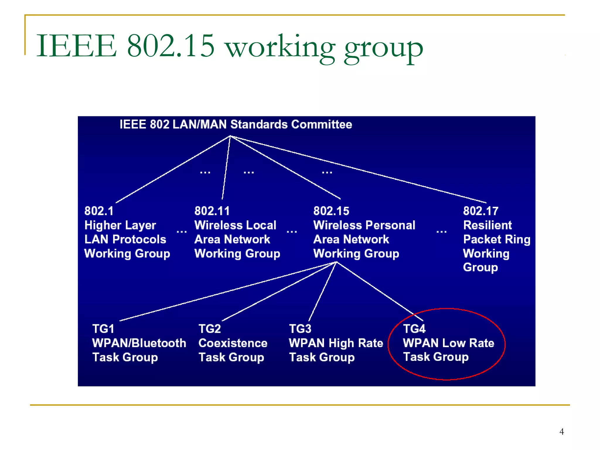
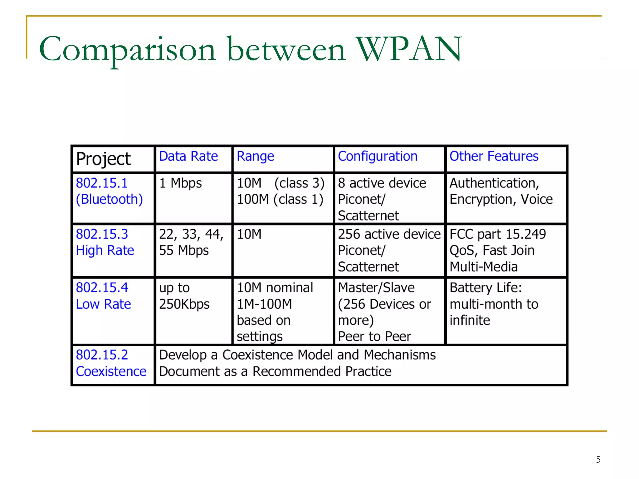
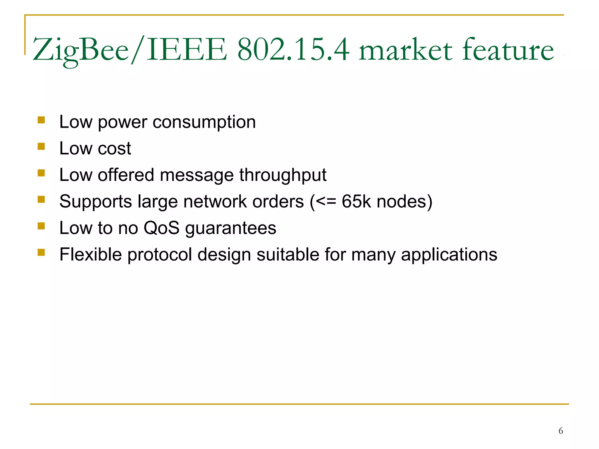
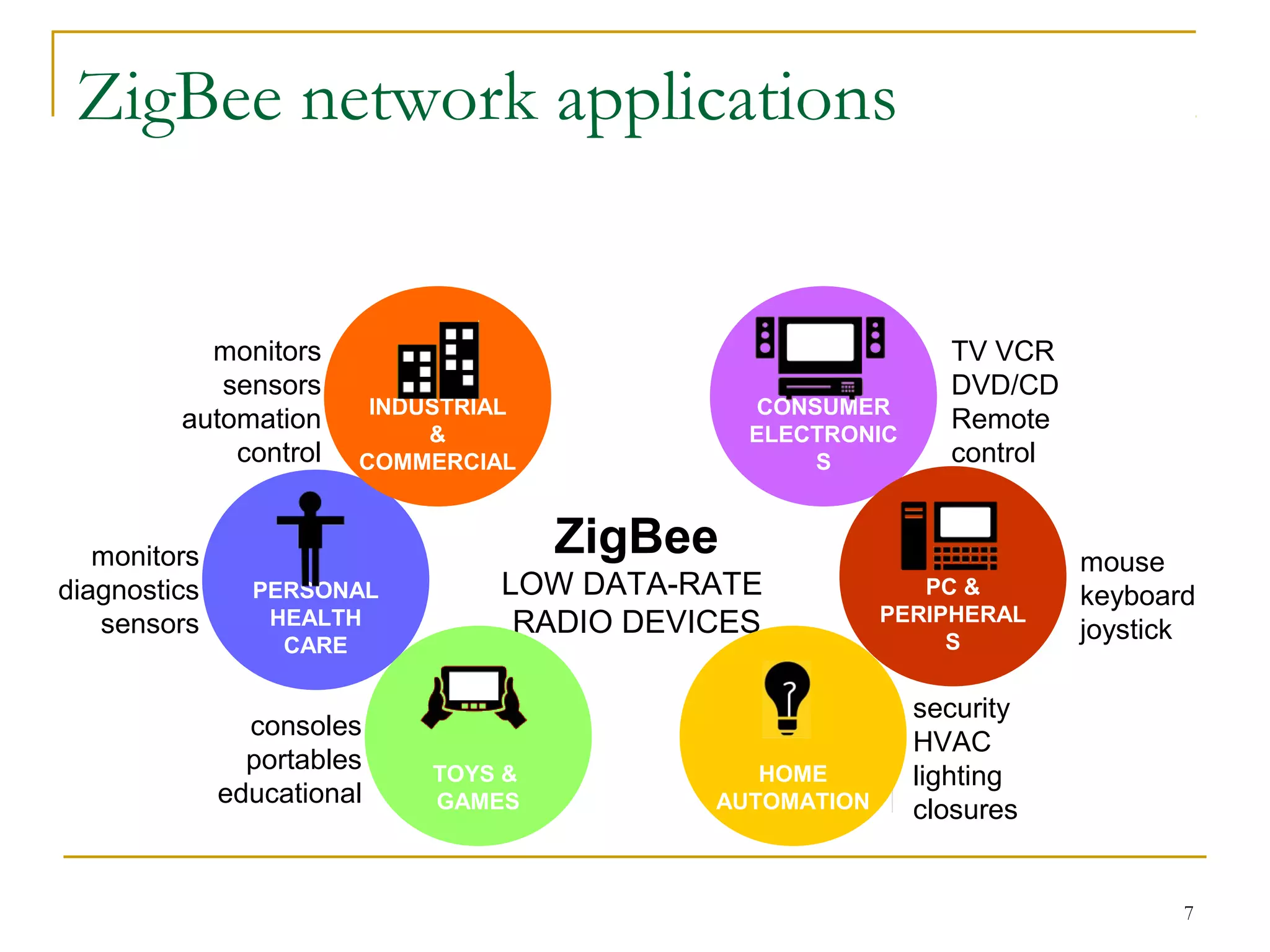
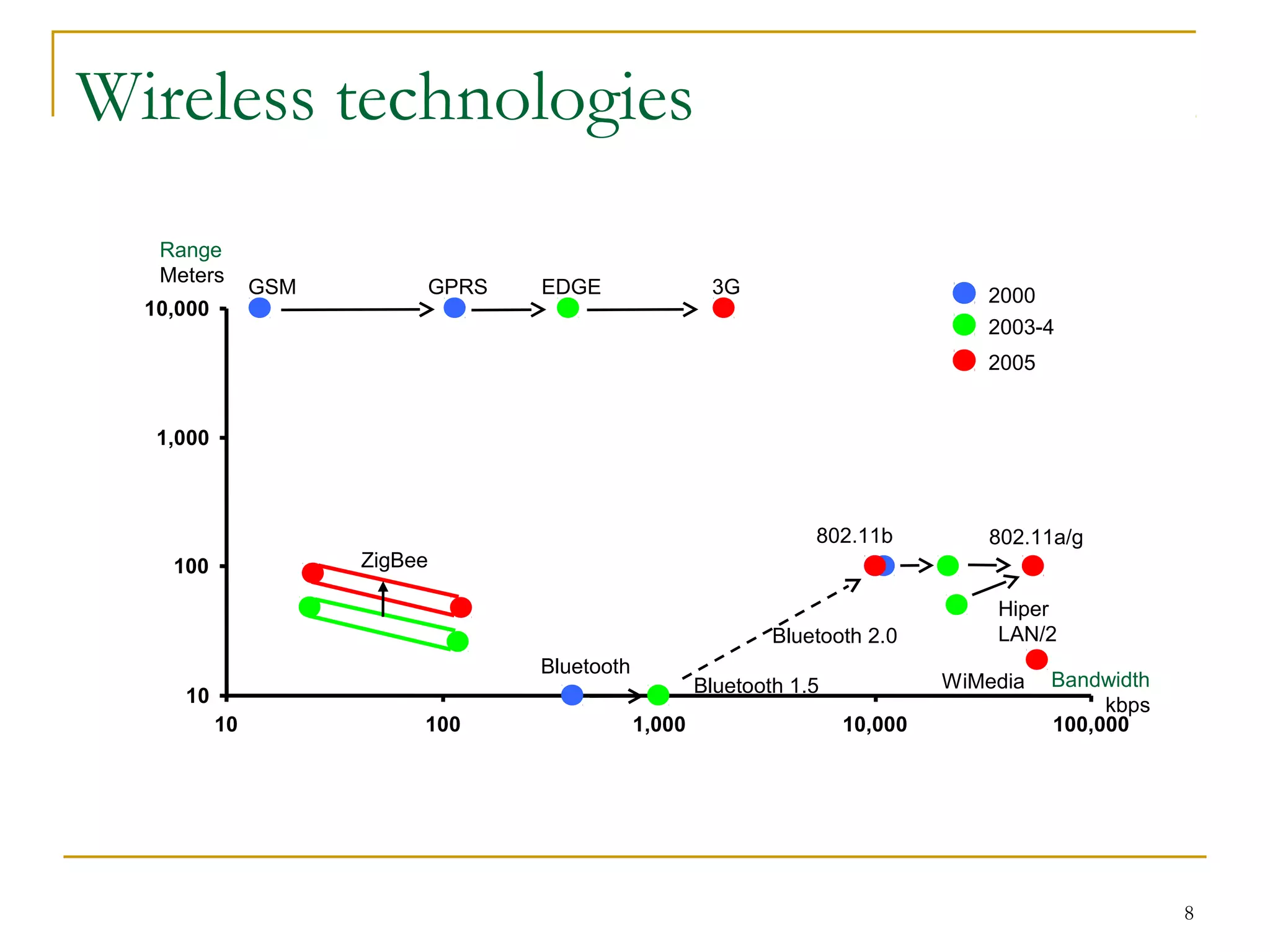


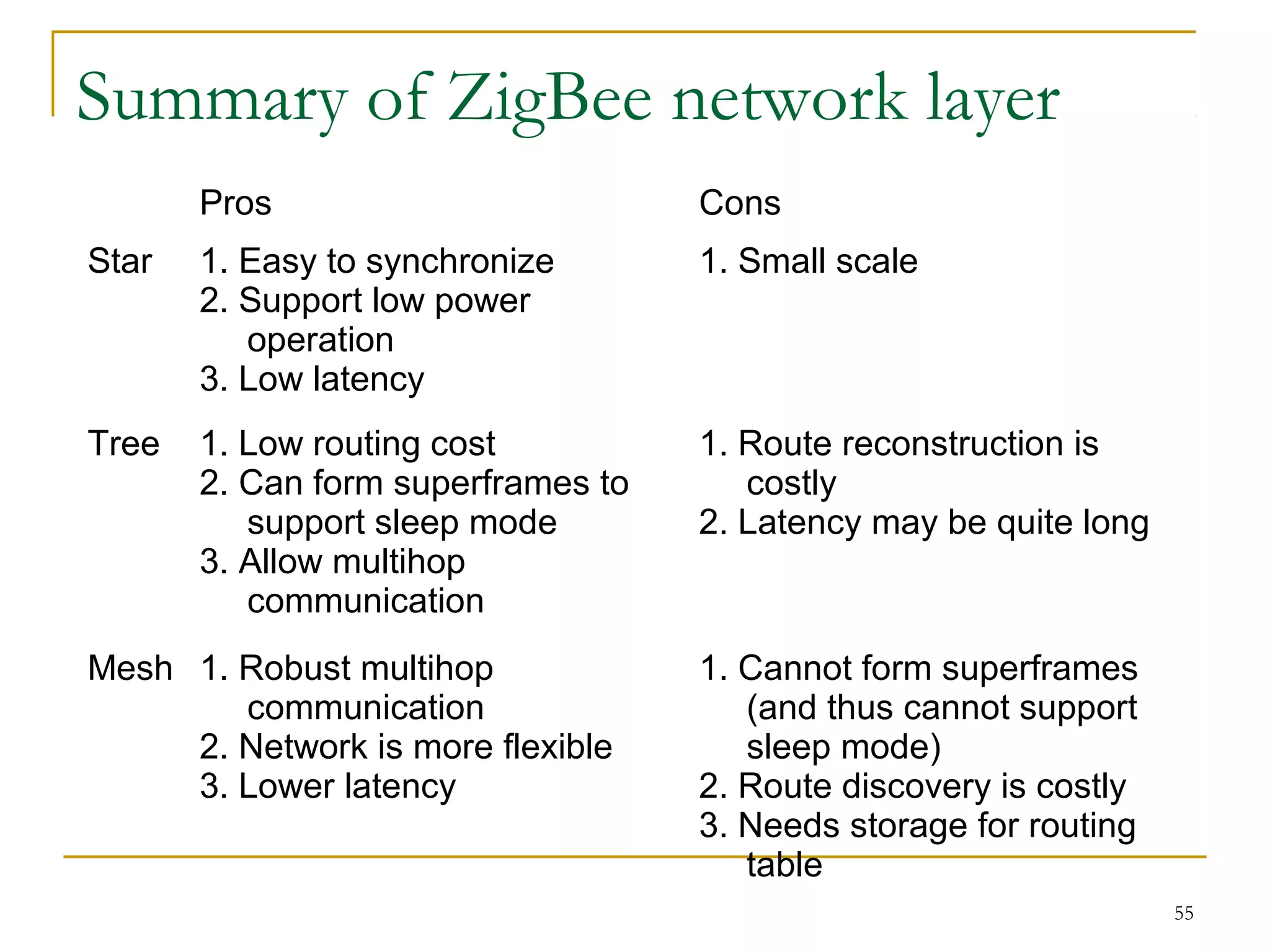

The document provides an overview of ZigBee/IEEE 802.15.4 wireless technology. It discusses the need for low-power, low-cost wireless connectivity for applications like home automation, medical devices, and industrial sensors. It describes the ZigBee Alliance's role in developing networking and application standards on top of the IEEE 802.15.4 physical radio specification. Key features of ZigBee networks include low power consumption, large network capacity, low data rates, and flexibility for many applications.