The document discusses the building blocks of a SystemVerilog testbench. It describes the program block, which encapsulates test code and allows reading/writing signals and calling module routines. Interface and clocking blocks are used to connect the testbench to the design under test. Assertions, randomization, and other features help create flexible testbenches to verify design correctness.
![5
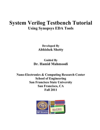
2. Building Blocks of Testbench
Fig 1
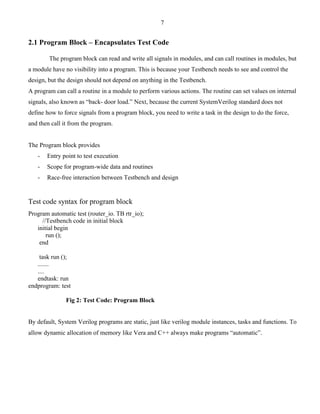
System Verilog Verification Features
These features assist in the creation of extensible, flexible test benches.
New Data Types:
int da[]; // dynamic array
int da[string]; // Associative array, indexed by string
int da[$]; // Queue
initial begin
da = new[16]; // Create 16 elements
end
The string data type represents a variable-length text string, which is a unique feature of System Verilog.
System Verilog offers dynamic arrays, associative arrays and queues. The array can be resized if needed.](https://image.slidesharecdn.com/systemverilogimportant-141202045052-conversion-gate01/85/System-verilog-important-5-320.jpg)
![6
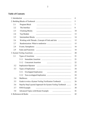
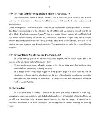
The queue provides much of the C++ STL deque type: elements can be added and removed from either
end efficiently. Complex data structures can be created for score boarding a large design.
Classes
System Verilog provides an object-oriented programming model.
System Verilog classes support a single-inheritance model. There is no facility that permits
conformance of a class to multiple functional interfaces, such as the interface feature of Java. System
Verilog classes can be type-parameterized, providing the basic function of C++ templates. However,
function templates and template specialization are not supported.
The polymorphism features are similar to those of C++: the programmer may specify write a
virtual function to have a derived class gain control of the function. Encapsulation and data hiding is
accomplished using the local and protected keywords, which must be applied to any item that is to be
hidden. By default, all class properties are public. System Verilog class instances are created with the new
keyword. A constructor denoted by function new can be defined. System Verilog supports garbage
collection, so there is no facility to explicitly destroy class instances.
Example:
virtual class Memory;
virtual function bit [31:0] read(bit [31:0] addr); endfunction
virtual function void write(bit [31:0] addr, bit [31:0] data);
endfunction
endclass
class SRAM #(parameter AWIDTH=10) extends Memory;
bit [31:0] mem [1<<AWIDTH];
virtual function bit [31:0] read (bit [31:0] addr);
return mem [addr];
endfunction
virtual function void write(bit [31:0] addr, bit [31:0] data);
mem[addr] = data;
endfunction
endclass
There are other important features like Randomization, Assertions, and Coverage, which is discussed in
future sections.](https://image.slidesharecdn.com/systemverilogimportant-141202045052-conversion-gate01/85/System-verilog-important-6-320.jpg)


![13
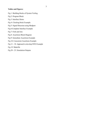
- Modports do not contain vector sizes or data types (common error) – only whether the connecting
module sees a signal as input, output, inout or ref port.
2.4 Module Top: This file carries the top-level image of your whole design showing all the modules
connected to it and the ports being used for the design. The interface and test programs are instantiated
here in the harness files. Looking at into a top level harness files gives an detailed picture of any design,
as to what are the functional parameters, interfaces etc.
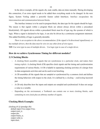
A Complete Interface
Fig 6
interface router_io (input bit clock)
logic reset_n;
logic [15:0] din;
logic [15:0] frame_n;
logic [15:0] valid_n;
logic [15:0] dout;
logic [15:0] busy_n;
logic [15:0] valido_n;
logic [15:0] frameo_n;
clocking cb @ (posedge clock)
default input #1 output #1
output reset_n;
output din;
output frame_n;
output valid_n;
output dout;
output busy_n;
output valido_n;
input frameo_n;
endclocking
modport TB(clocking cb, output reset_n);
endinterface
Named bundle of
asynchronous signals
Create synchronous
behavior by placing
into clocking block
Define direction and
access with modport
Synchronous Asynchronous](https://image.slidesharecdn.com/systemverilogimportant-141202045052-conversion-gate01/85/System-verilog-important-13-320.jpg)


![19
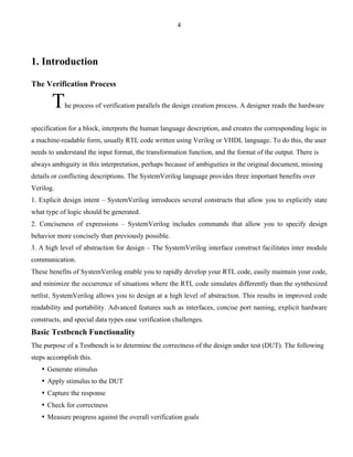
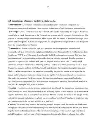
Semaphores can be used in a testbench when you have a resource, such as a bus, that may have multiple
requestors from inside the testbench but as part of the physical design, can only has one driver. There are
three basic operations for a semaphore. We create a semaphore with one or more keys using the new
method get one or more keys with get, and return one or more keys with put.
Eg: Semaphore
program automatic test (...)
semaphore sem;
initial begin
sem = new(1); //Allocate with 1 key
fork
......
......
join
end
task send;
sem.get(1);
....
....
sem.put(1);
endtask
endprogram
2.9 Tasks and Functions
Task and Function declarations are similar as in Verilog but following rules hold good for system
verilog.
• Any port is seen as input default port direction, unless explicitly declared as other types. Eg: in,
out, inout, ref.
• Unless declared, data types of ports are of logic type.
• There is no need to use begin..end when more then one statement is used inside a task.
• A task can be terminated before endtask, by usage of return statement.
• Wire data type cannot be used inside the port list.
Eg: Task
module task_intro ();
initial begin
#1 doInit(4,5);
#1 doInit(9,6);
#1 $finish;
end
task doInit(input bit [3:0] count, delay);
automatic reg [7:0] a;](https://image.slidesharecdn.com/systemverilogimportant-141202045052-conversion-gate01/85/System-verilog-important-19-320.jpg)
![20
if (count > 5) begin
$display ( “ @ %t ns Returning from task”, $time);
return;
end
#5 $display (“@ %t ns Value passed is %dn”, $time, count);
endtask
endmodule
Output:
@6 ns Value passed is 4
@7 ns Returning from task
Eg: Function
module task_intro ();
bit a;
initial begin
#1 a = doInit(4,5);
#1 a = doInit(9,6);
#1 $finish;
end
function bit unsigned doInit(bit [3:0] count, add);
automatic reg [7:0] b;
if (count > 5) begin
$display ( “ @ %t ns Returning from task”, $time);
return 0;
end
b = add;
#5 $display (“@ %t ns Value passed is %dn”, $time, count + b);
doInit = 1;
endfunction
endmodule
Output:
@1 ns Value passed is 9
@2 ns Returning from function
With the above examples we can clearly define where task and functions can be used effectively.
3. System Verilog Assertion (SVA):
GENERATOR](https://image.slidesharecdn.com/systemverilogimportant-141202045052-conversion-gate01/85/System-verilog-important-20-320.jpg)

![22
How does Assertions looks like????
SVA Syntax Example:
assert property ********* keywords********
(@(posedge clk) $rose(req) |-> ##[1:3] $rose(ack));
In the above example, when there is a positive edge on the Request (req) signal, then make sure that
between 1 and 3 clock cycles later, there is a positive edge on acknowledge (ack) signal.
Here the designer knows that the acknowledge signal should go high within 1 to 3 cycles as soon as the
Request signal has gone high at the positive edge.
3.1 Types of Assertions:
3.1.1 Immediate Assertions:
Immediate Assertions check the state of a condition at a given point in time.
- Based on simulation event semantics.
- Test expression is evaluated just like any other. Verilog expression with a procedural block. Those
are not temporal in nature and are evaluated immediately.
- Have to be placed in a procedural block definition.
- Used only with dynamic simulation
A sample immediate assertion is shown below:
always_comb
begin
a_ia: assert (a && b);
end
The immediate assertion a_ia is written as part of a procedural block and it follows the same event
schedule of signal “a” and “b”. The always block executes if either signal “a” or signal “b” changes. The
keyword that differentiates the immediate assertion from the concurrent assertion is property.](https://image.slidesharecdn.com/systemverilogimportant-141202045052-conversion-gate01/85/System-verilog-important-22-320.jpg)


![36
Fig 19: Makefile
Once all the blocks are set and being linked up with the help of Makefile, we can execute all these files to
check the functionality of our Testbench by executing the below commands.
Type ssh -X <username>@hafez.sfsu.edu on the shell window to login to your respective accounts.
On execution of above command, it prompts to enter your password. Note: Entry of password is not
physically visible to the user. On successful login, user is now ready inside the server.
To activate the C shell, type the below command as shown. Without executing this command, all other
commands seem to be invalid to the interpreter and throw an error message upon execution.
[engr852-19@hafez ~]$ csh
Source the Synopsys setup files using below command
[engr852-19@hafez~]$source /packages/synopsys/setup/synopsys_setup.tcl
I strongly suggest, giving a try and writing your own Testbench with the above references.
Parallely, you can copy the solutions into your home directory by running the below command.](https://image.slidesharecdn.com/systemverilogimportant-141202045052-conversion-gate01/85/System-verilog-important-36-320.jpg)
![37
[engr852-19@hafez~]$ cp -rpf /packages/synopsys/setup/verification_flow/System_Verilog/fifo_example ./
Execute the below command where all the above said design files (Eg: FIFO design files) are being
located in your Unix directory.
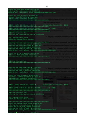
[engr852-19@hafez example1]$ make > report.log
On execution of above command, the make file is being executed and saves the output in report.log file.
Below an example of report.log is shown for FIFO example.
“make” is a command, which triggers the script called “Makefile” as shown above in Fig 19. This
script basically contains the actual commands which needs to be executed, and are assigned to a variable.
This makes life easier for a programmer and user to understand the design hierarchy. You have just
mastered the art of good programming practice, by writing a Makefile for your design. A developer is
expected to write a Makefile to compile & execute his/her project.
The report.log gives exact idea about the execution flow and which process is taking place at specific
timing cycle. To make a successful testbench for a design, the requirements of both the testbench and the
design should be common. If there is any change in the requirements, the testbench might not be able to
test the design’s all features successfully. With suitable error and success commands, we can check if the
testbench works fine for the given design.
The testbench developer can write suitable display messages, which comes on the report.log when
executed and helps to debug if any of the requirements are not matching.](https://image.slidesharecdn.com/systemverilogimportant-141202045052-conversion-gate01/85/System-verilog-important-37-320.jpg)
![39
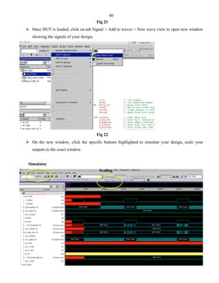
[engr852-19@hafez example1]$ ./simv –gui
Upon execution of the above command, a new window opens as shown below
Fig 20
Click the DUT of the design and drag it to the white space provided in the center as shown below,
where you can view your code and modify it if necessary during the run.](https://image.slidesharecdn.com/systemverilogimportant-141202045052-conversion-gate01/85/System-verilog-important-39-320.jpg)

![42
3. Filtering conditions at multiple levels.
4. Events and sequences to automatically trigger coverage samples.
5. Procedural activation and query of coverage
6. Optional directives to control and regulate coverage
Scoreboard and Functional Coverage:
The main goal of a verification environment is to reach 100% coverage of the defined functional
coverage spec in the verification plan. Based on functional coverage analysis, the random based tests are
than constrained to focus on corner cases to get do complete functional check. Coverage is a generic term
for measuring progress to complete design verification. Simulations slowly paint the canvas of the design,
as we try to cover all of the legal combinations. The coverage tools gather information during a simulation
and then post process it to produce a coverage report. You can use this report to look for coverage holes
and then modify existing tests or create new ones to fill the holes.
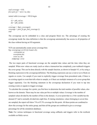
Covergroup: Covergroup is like a user-defined type that encapsulates and specifies the coverage. It can
be defined in a package, module, program, interface or class once defined multiple instances can be
created using new Parameters to new () enable customization of different instances. In all cases, we must
explicitly instantiate it to start sampling. If the cover group is defined in a class, you do not make a
separate name when we instance it. Cover group comprises of cover points, options, formal arguments,
and an optional trigger. A cover group encompasses one or more data points, all of which are sampled at
the same time.
Syntax Eg:
covergroup cg;
// Coverage points
endgroup: cg
//create instance
cg cg_inst = new;
Eg 1: How to develop functional coverage block
1. Create a covergroup inside classes
2. Covergroup encapsulates coverage bins definitions (state, transition, cross correlation)
3. Coverage bins sample timing definition
4. Coverage attributes
covergroup fcov (ref bit [3:0] sa, da) @ (condition)
coverpoint sa;
coverpoint da;
endgroup: fcov
bit [3:0] sa, da;](https://image.slidesharecdn.com/systemverilogimportant-141202045052-conversion-gate01/85/System-verilog-important-42-320.jpg)
![44
Example: Router
Description of the router design:
1. The router has 16 input ports and 16 output ports. Each input has and output has 3 signals, serial data,
frame and valid. These signals are represented in a bit-vector format, din[15:0], frame_n[15:0],
valid_n[15:0], dout[15:0], valido_n[15:0] and frameo_n[15:0].
2. To drive individual port, the specific bit position corresponding to the port number must be specified.
For example, input port 3 is to be driven, and then the corresponding signals shall be din[3], frame_n[3]
and valid_n[3].
3. To sample an individual port, the specific bit position corresponding to the port number shall be
specified. For example, if output port 7 is to be sampled, then the corresponding signals shall be dout[7],
frameo_n[7] and valido_n[7].
4. Packets are sent in variable length, composed of header and payload.
5. Packets can be routed from any input port to any output port.
4. References & Books
[1] “System Verilog for Verification, A Guide to Learning the Testbench Language Features”, by Chris
Spears, Second Edition.
[2] www.testbench.in
[3] “System Verilog for Design, A Guide to Using System Verilog for Hardware Design and Modeling”,
by Stuart Sutherland, Simon and Peter Flake.
[4] http://www.systemverilog.in/systemverilog.php
[5] http://www.design-reuse.com/articles/22264/system-verilog-ovm-verification-reusability.html
[6] http://events.dvcon.org/2011/proceedings/papers/01_3.pdf](https://image.slidesharecdn.com/systemverilogimportant-141202045052-conversion-gate01/85/System-verilog-important-44-320.jpg)