Webinar: High Voltage Fiber Optic (HVFO) Probe for Small Signal Floating Measurements
The document is a summary of a webinar held on June 21, 2017, regarding high voltage fiber optic probes, detailing Teledyne LeCroy's background and probe types, including their specifications and applications in power electronics. It emphasizes the importance of selecting appropriate probes for safe and accurate measurements in high voltage scenarios and compares different types of high voltage probes. The presentation also includes product highlights of the HVFO103 probe, including key features, included components, and available tip accessories.
Webinar: High Voltage Fiber Optic (HVFO) Probe for Small Signal Floating Measurements
1.
WEBINAR:
High Voltage FiberOptic Probe
June 21st, 2017
Thank you for joining us. We will begin at 2:00pm EDST.
NOTE: This presentation includes Q&A. We will be taking
questions during the presentation with answers at the end using
the questions section of your control panel
June 21, 2017 1
2.
Teledyne LeCroy Overview
June21, 2017 2
LeCroy was founded in 1964 by Walter
LeCroy
Original products were high-speed digitizers for
particle physics research
Corporate headquarters is in Chestnut
Ridge, NY
Long history of innovation in digital
oscilloscopes
First digital storage oscilloscope
Highest bandwidth real-time oscilloscope
(100 GHz)
World’s only 12-bit, 1 GHz, 8ch oscilloscope
LeCroy became the world leader in protocol
analysis with the purchase of CATC and
Catalyst
Frontline Test Equipment and Quantum Data
were also recently acquired (2016)
In 2012, LeCroy was acquired by Teledyne
Technologies and renamed Teledyne LeCroy
3.
• Product Managerwith Teledyne LeCroy
for over 15 years
• B.S., Electrical Engineering from
Rensselaer Polytechnic Institute
• Awarded three U.S. patents for in the
field of simultaneous physical layer and
protocol analysis
Ken Johnson
Director of Marketing, Product Architect
Teledyne LeCroy
ken.johnson@teledynelecroy.com
June 21, 2017 3
About the Presenter
4.
Agenda
Probe Typesand Characteristics
Probe Fit to Various Applications
Highly Relevant Probe Specifications
HVFO103 Product Overview
HVFO103 Probing Comparisons
Summary
Questions
June 21, 2017 4
5.
Probe Types andCharacteristics
High voltages present in power electronics requires care in selecting a
probe that is safe to use. But just because a probe is safe to use does
not mean that it will provide a good measurement result.
June 21, 2017 5
6.
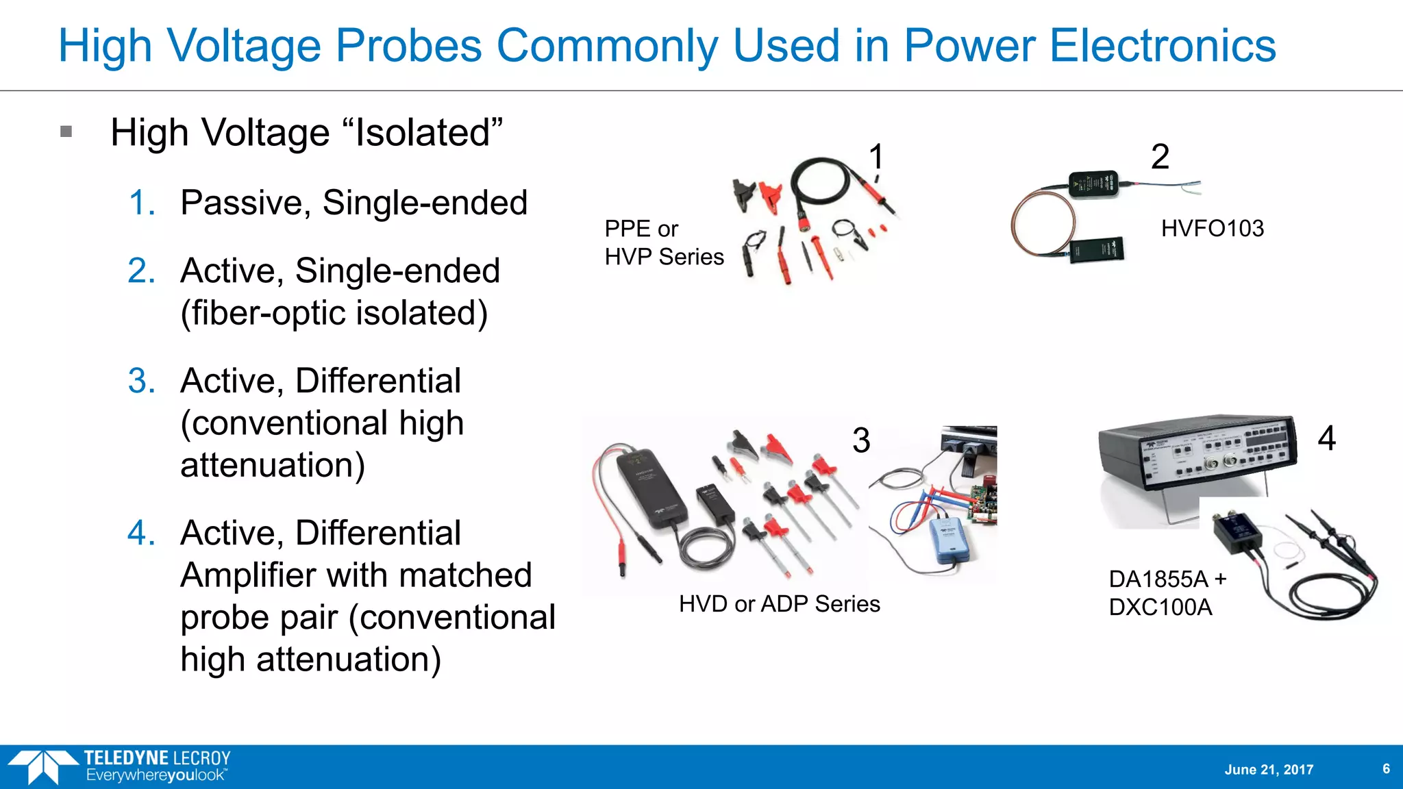
High Voltage ProbesCommonly Used in Power Electronics
High Voltage “Isolated”
1. Passive, Single-ended
2. Active, Single-ended
(fiber-optic isolated)
3. Active, Differential
(conventional high
attenuation)
4. Active, Differential
Amplifier with matched
probe pair (conventional
high attenuation)
1 2
3 4
PPE or
HVP Series
HVFO103
HVD or ADP Series
DA1855A +
DXC100A
June 21, 2017 6
7.
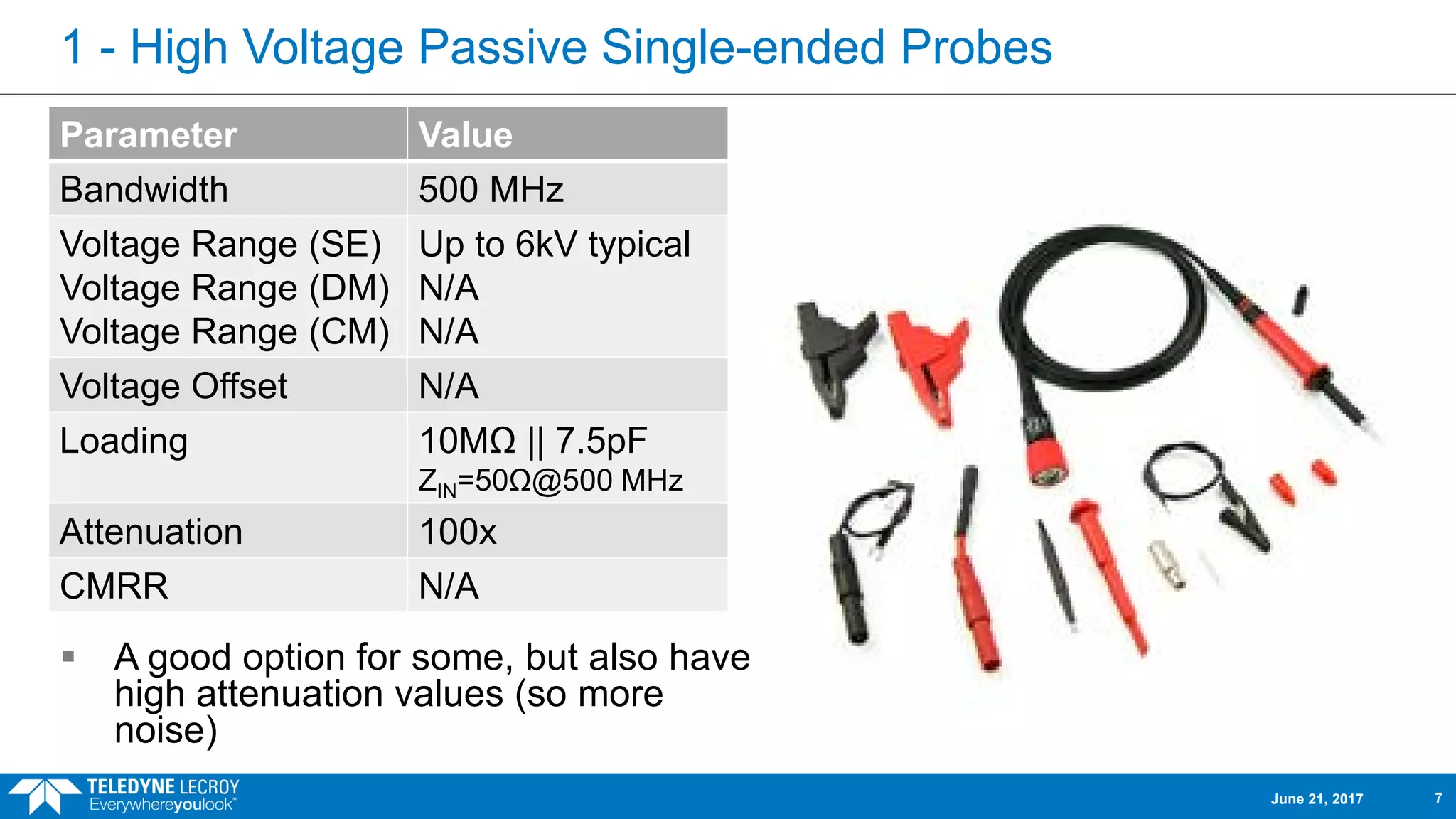
1 - HighVoltage Passive Single-ended Probes
Parameter Value
Bandwidth 500 MHz
Voltage Range (SE)
Voltage Range (DM)
Voltage Range (CM)
Up to 6kV typical
N/A
N/A
Voltage Offset N/A
Loading 10MΩ || 7.5pF
ZIN=50Ω@500 MHz
Attenuation 100x
CMRR N/A
A good option for some, but also have
high attenuation values (so more
noise)
June 21, 2017 7
8.
2 - HighVoltage Active Single-ended (Fiber Optic) Probes
A new topology specifically for
measuring small signals floating on
a HV DC bus
Parameter Value
Bandwidth 60 MHz
Voltage Range (SE)
Voltage Range (DM)
Voltage Range (CM)
2 to 80V
N/A
Virtually Unlimited
Voltage Offset N/A
Loading 1-10MΩ || 34-22pF
ZIN=50kΩ@100 kHz
Attenuation 2x to 80x
CMRR >140 dB
June 21, 2017 8
9.
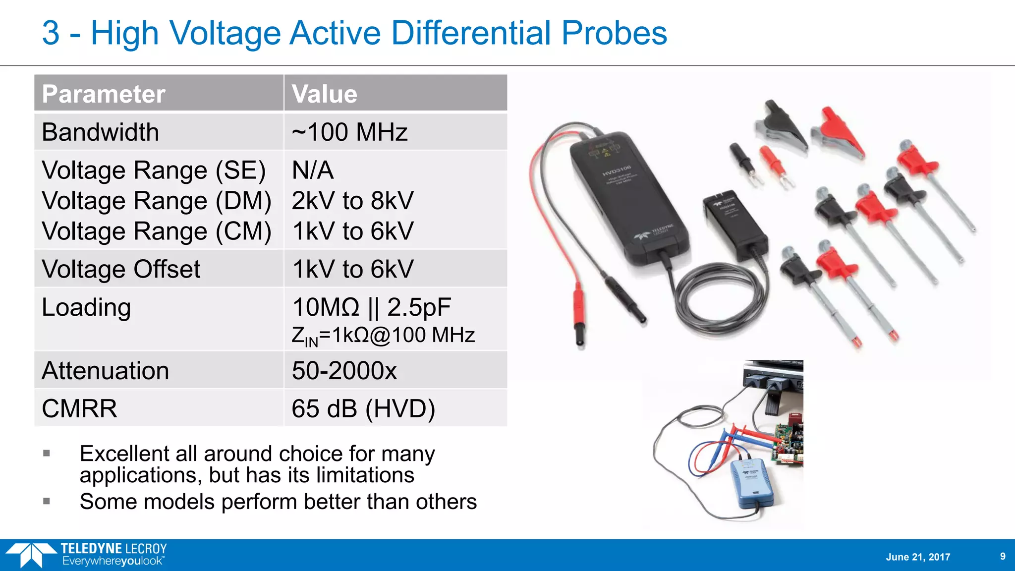
3 - HighVoltage Active Differential Probes
Excellent all around choice for many
applications, but has its limitations
Some models perform better than others
Parameter Value
Bandwidth ~100 MHz
Voltage Range (SE)
Voltage Range (DM)
Voltage Range (CM)
N/A
2kV to 8kV
1kV to 6kV
Voltage Offset 1kV to 6kV
Loading 10MΩ || 2.5pF
ZIN=1kΩ@100 MHz
Attenuation 50-2000x
CMRR 65 dB (HVD)
June 21, 2017 9
10.
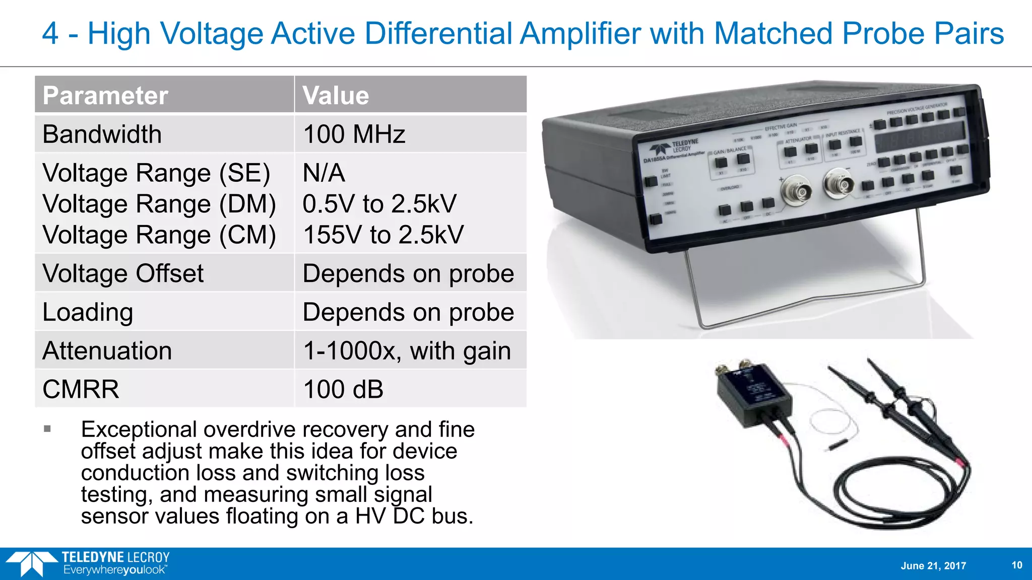
4 - HighVoltage Active Differential Amplifier with Matched Probe Pairs
Exceptional overdrive recovery and fine
offset adjust make this idea for device
conduction loss and switching loss
testing, and measuring small signal
sensor values floating on a HV DC bus.
Parameter Value
Bandwidth 100 MHz
Voltage Range (SE)
Voltage Range (DM)
Voltage Range (CM)
N/A
0.5V to 2.5kV
155V to 2.5kV
Voltage Offset Depends on probe
Loading Depends on probe
Attenuation 1-1000x, with gain
CMRR 100 dB
June 21, 2017 10
11.
Polling Question #1
What types of probes do you use? (select one or more answers)
High Voltage Passive Single-ended Probes
High Voltage Active Single-ended (Fiber Optic) Probes
High Voltage Active Differential Probes
High Voltage Active Differential Amplifier with Matched Probe Pairs
June 21, 2017 11
12.
Probe Fit toVarious Applications
Some probes perform better than others in certain applications, and some
should never be used when high voltage signals are being measured.
June 21, 2017 12
13.
Color Code forthe Application Tables that Follow
This is the perfect probe for the application. There are few
issues with its use, and it has been optimized in price and
performance for this application.
There are some compromises in performance of the probe in
this application, though some users may find the probe works
fine for them.
While the probe will provide a result and will not be damaged in
making the measurement, most users would find the probe does
not work well in this application.
The probe should absolutely not be used in this application as
damage to the probe, oscilloscope or device under test (DUT)
may occur, or harm may come to the operator.
June 21, 2017 13
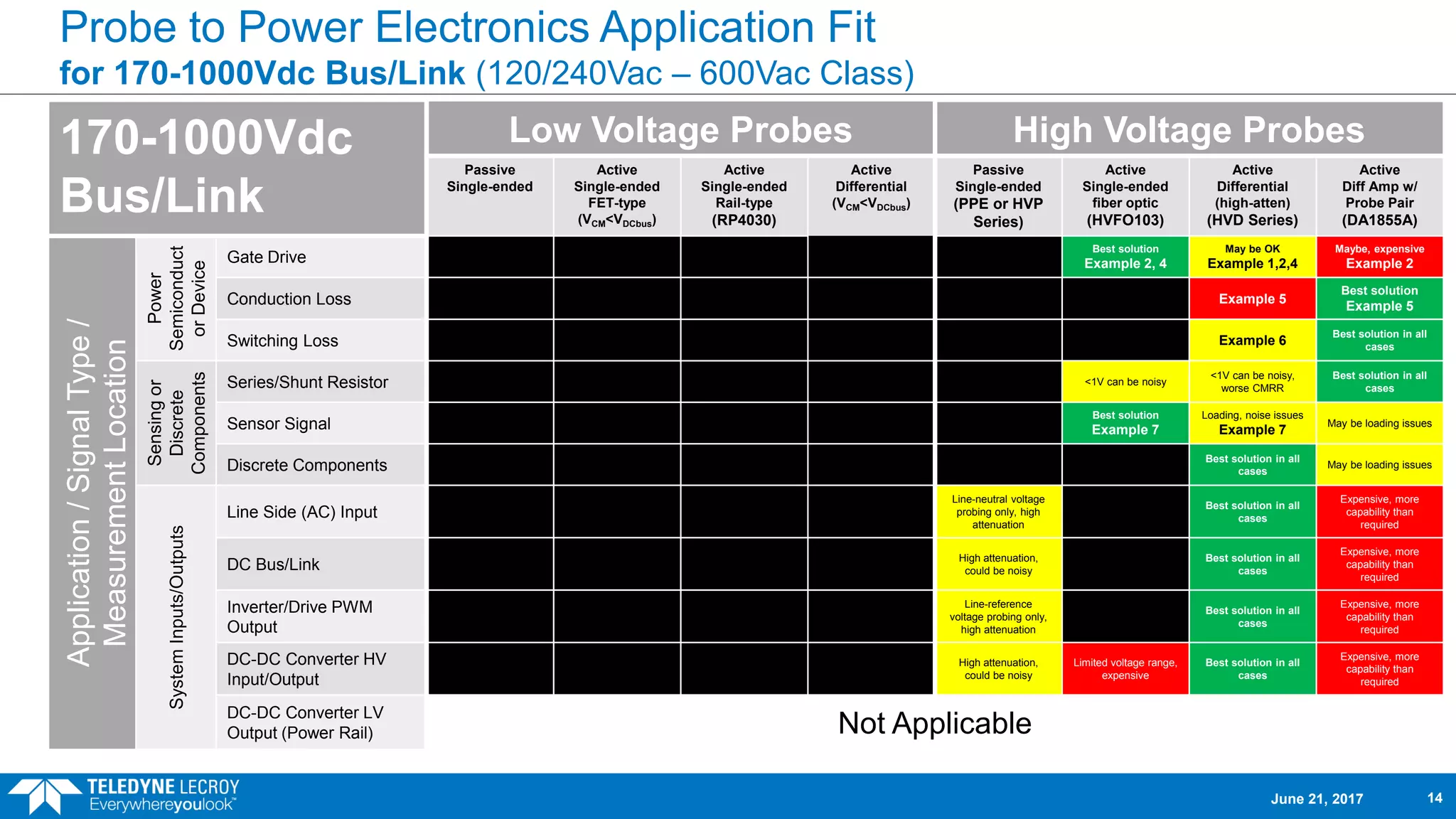
14.
Probe to PowerElectronics Application Fit
for 170-1000Vdc Bus/Link (120/240Vac – 600Vac Class)
170-1000Vdc
Bus/Link
Low Voltage Probes High Voltage Probes
Passive
Single-ended
Active
Single-ended
FET-type
(VCM<VDCbus)
Active
Single-ended
Rail-type
(RP4030)
Active
Differential
(VCM<VDCbus)
Passive
Single-ended
(PPE or HVP
Series)
Active
Single-ended
fiber optic
(HVFO103)
Active
Differential
(high-atten)
(HVD Series)
Active
Diff Amp w/
Probe Pair
(DA1855A)
Application/SignalType/
MeasurementLocation
Power
Semiconduct
orDevice
Gate Drive
Best solution
Example 2, 4
May be OK
Example 1,2,4
Maybe, expensive
Example 2
Conduction Loss Example 5
Best solution
Example 5
Switching Loss Example 6
Best solution in all
cases
Sensingor
Discrete
Components
Series/Shunt Resistor <1V can be noisy
<1V can be noisy,
worse CMRR
Best solution in all
cases
Sensor Signal
Best solution
Example 7
Loading, noise issues
Example 7
May be loading issues
Discrete Components
Best solution in all
cases
May be loading issues
SystemInputs/Outputs
Line Side (AC) Input
Line-neutral voltage
probing only, high
attenuation
Best solution in all
cases
Expensive, more
capability than
required
DC Bus/Link
High attenuation,
could be noisy
Best solution in all
cases
Expensive, more
capability than
required
Inverter/Drive PWM
Output
Line-reference
voltage probing only,
high attenuation
Best solution in all
cases
Expensive, more
capability than
required
DC-DC Converter HV
Input/Output
High attenuation,
could be noisy
Limited voltage range,
expensive
Best solution in all
cases
Expensive, more
capability than
required
DC-DC Converter LV
Output (Power Rail) Not Applicable
June 21, 2017 14
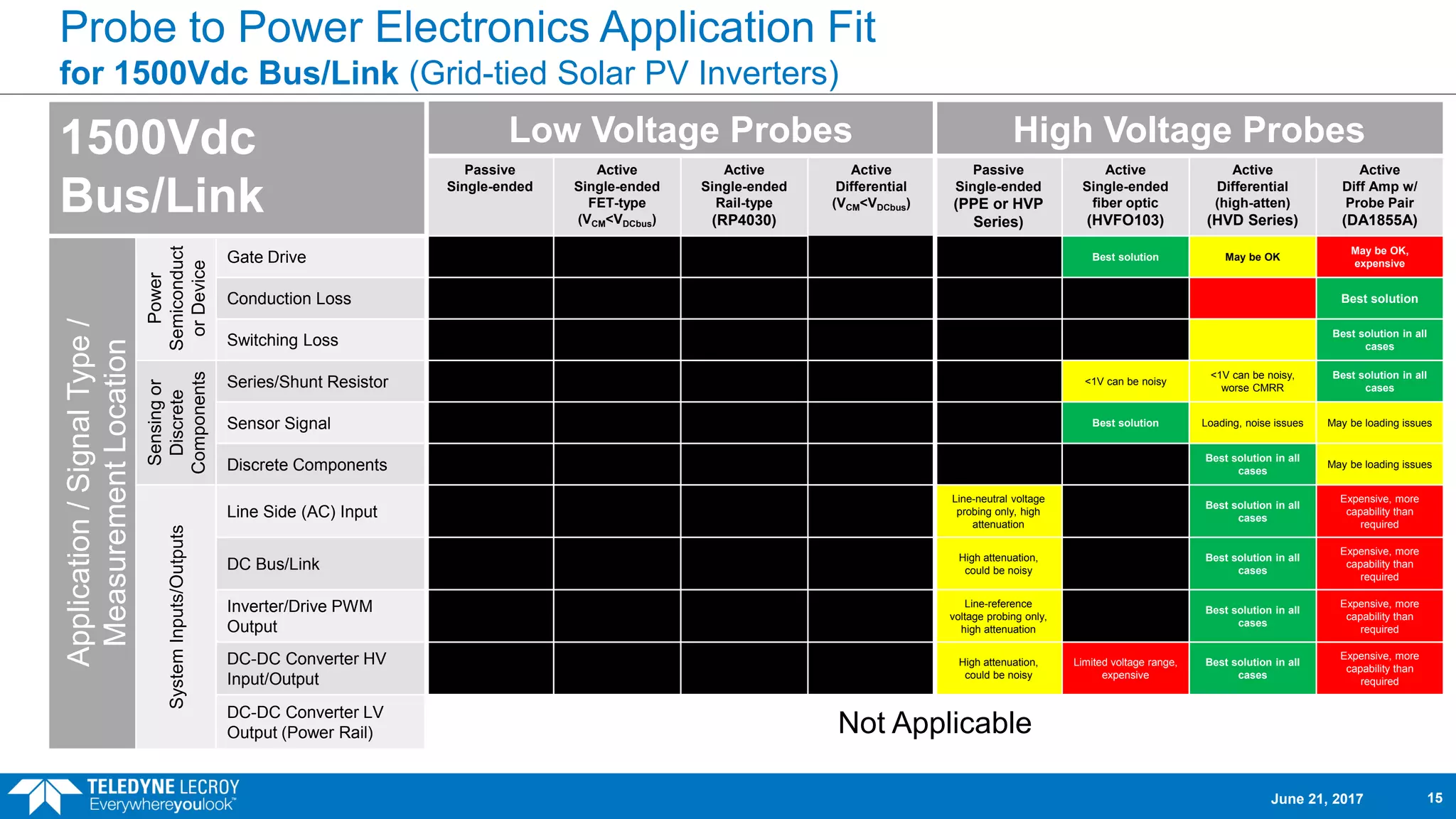
15.
Probe to PowerElectronics Application Fit
for 1500Vdc Bus/Link (Grid-tied Solar PV Inverters)
1500Vdc
Bus/Link
Low Voltage Probes High Voltage Probes
Passive
Single-ended
Active
Single-ended
FET-type
(VCM<VDCbus)
Active
Single-ended
Rail-type
(RP4030)
Active
Differential
(VCM<VDCbus)
Passive
Single-ended
(PPE or HVP
Series)
Active
Single-ended
fiber optic
(HVFO103)
Active
Differential
(high-atten)
(HVD Series)
Active
Diff Amp w/
Probe Pair
(DA1855A)
Application/SignalType/
MeasurementLocation
Power
Semiconduct
orDevice
Gate Drive Best solution May be OK
May be OK,
expensive
Conduction Loss Best solution
Switching Loss
Best solution in all
cases
Sensingor
Discrete
Components
Series/Shunt Resistor <1V can be noisy
<1V can be noisy,
worse CMRR
Best solution in all
cases
Sensor Signal Best solution Loading, noise issues May be loading issues
Discrete Components
Best solution in all
cases
May be loading issues
SystemInputs/Outputs
Line Side (AC) Input
Line-neutral voltage
probing only, high
attenuation
Best solution in all
cases
Expensive, more
capability than
required
DC Bus/Link
High attenuation,
could be noisy
Best solution in all
cases
Expensive, more
capability than
required
Inverter/Drive PWM
Output
Line-reference
voltage probing only,
high attenuation
Best solution in all
cases
Expensive, more
capability than
required
DC-DC Converter HV
Input/Output
High attenuation,
could be noisy
Limited voltage range,
expensive
Best solution in all
cases
Expensive, more
capability than
required
DC-DC Converter LV
Output (Power Rail) Not Applicable
June 21, 2017 15
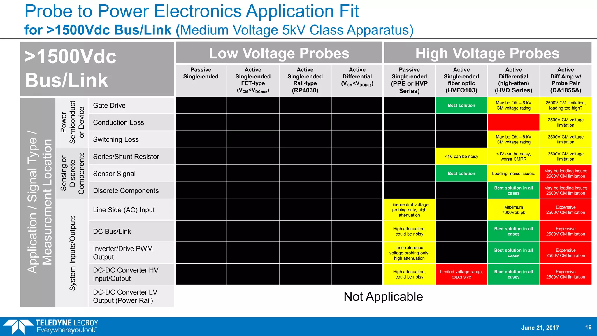
16.
Probe to PowerElectronics Application Fit
for >1500Vdc Bus/Link (Medium Voltage 5kV Class Apparatus)
>1500Vdc
Bus/Link
Low Voltage Probes High Voltage Probes
Passive
Single-ended
Active
Single-ended
FET-type
(VCM<VDCbus)
Active
Single-ended
Rail-type
(RP4030)
Active
Differential
(VCM<VDCbus)
Passive
Single-ended
(PPE or HVP
Series)
Active
Single-ended
fiber optic
(HVFO103)
Active
Differential
(high-atten)
(HVD Series)
Active
Diff Amp w/
Probe Pair
(DA1855A)
Application/SignalType/
MeasurementLocation
Power
Semiconduct
orDevice
Gate Drive Best solution
May be OK – 6 kV
CM voltage rating
2500V CM limitation,
loading too high?
Conduction Loss
2500V CM voltage
limitation
Switching Loss
May be OK – 6 kV
CM voltage rating
2500V CM voltage
limitation
Sensingor
Discrete
Components
Series/Shunt Resistor <1V can be noisy
<1V can be noisy,
worse CMRR
2500V CM voltage
limitation
Sensor Signal Best solution Loading, noise issues.
May be loading issues
2500V CM limitation
Discrete Components
Best solution in all
cases
May be loading issues
2500V CM limitation
SystemInputs/Outputs
Line Side (AC) Input
Line-neutral voltage
probing only, high
attenuation
Maximum
7600Vpk-pk
Expensive
2500V CM limitation
DC Bus/Link
High attenuation,
could be noisy
Best solution in all
cases
Expensive
2500V CM limitation
Inverter/Drive PWM
Output
Line-reference
voltage probing only,
high attenuation
Best solution in all
cases
Expensive
2500V CM limitation
DC-DC Converter HV
Input/Output
High attenuation,
could be noisy
Limited voltage range,
expensive
Best solution in all
cases
Expensive
2500V CM limitation
DC-DC Converter LV
Output (Power Rail) Not Applicable
June 21, 2017 16
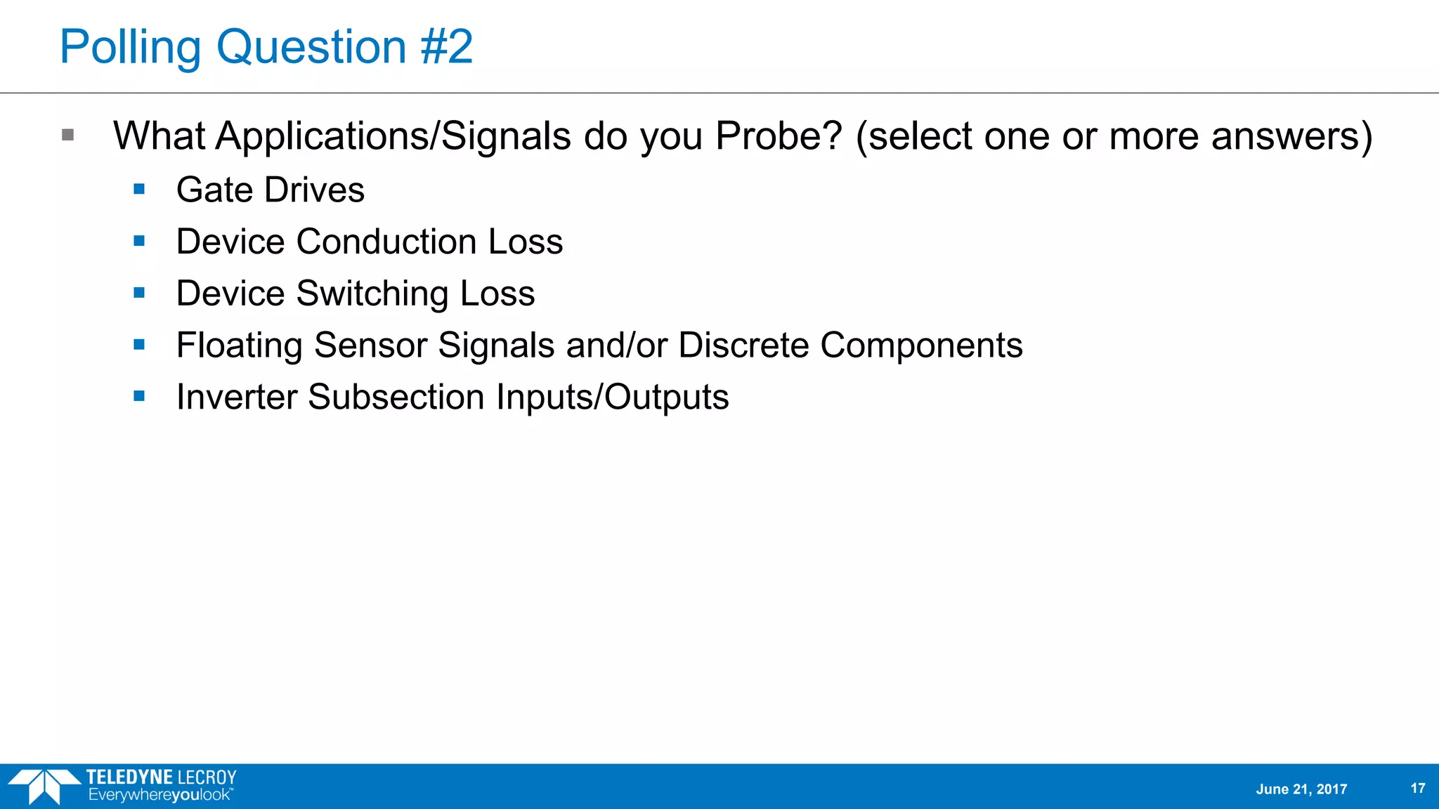
17.
Polling Question #2
What Applications/Signals do you Probe? (select one or more answers)
Gate Drives
Device Conduction Loss
Device Switching Loss
Floating Sensor Signals and/or Discrete Components
Inverter Subsection Inputs/Outputs
June 21, 2017 17
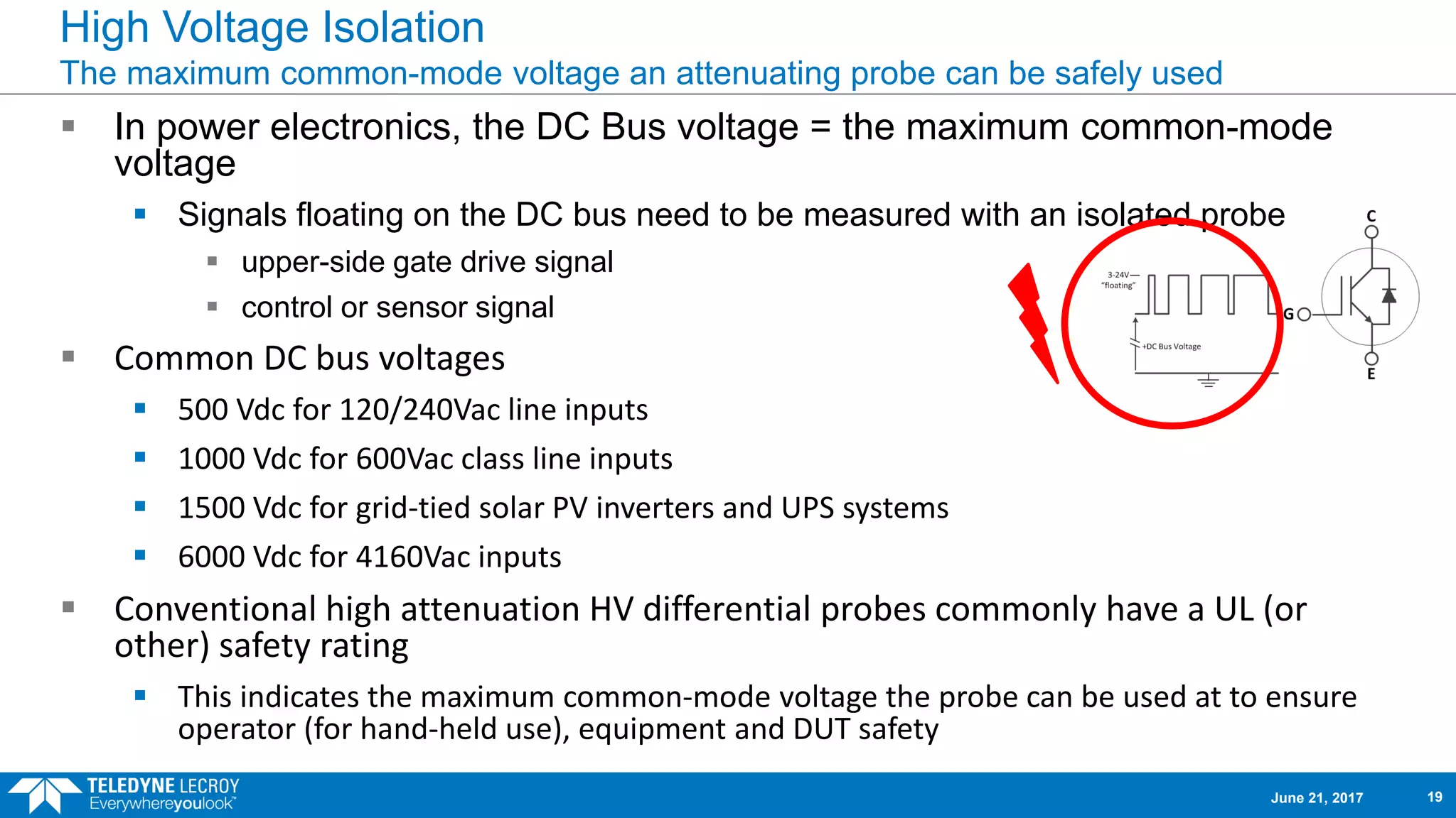
High Voltage Isolation
Themaximum common-mode voltage an attenuating probe can be safely used
In power electronics, the DC Bus voltage = the maximum common-mode
voltage
Signals floating on the DC bus need to be measured with an isolated probe
upper-side gate drive signal
control or sensor signal
Common DC bus voltages
500 Vdc for 120/240Vac line inputs
1000 Vdc for 600Vac class line inputs
1500 Vdc for grid-tied solar PV inverters and UPS systems
6000 Vdc for 4160Vac inputs
Conventional high attenuation HV differential probes commonly have a UL (or
other) safety rating
This indicates the maximum common-mode voltage the probe can be used at to ensure
operator (for hand-held use), equipment and DUT safety
June 21, 2017 19
20.
Common Mode RejectionRatio (CMRR)
Common Mode Rejection is the ability of the differential amplifier to ignore the
component that is common to both inputs.
Real world differential amplifiers do not remove all of the common mode signal.
Additionally, differential probe leads/pairs must be perfectly matched for frequency
response. This is hard to do with an attenuating probe lead set (but good results can still be
obtained).
Common mode feedthrough sums with the VDM (signal of interest) into the output of the
differential amplifier, becoming indistinguishable from the true signal.
The measure of how effective the differential amplifier + probe lead (pair) system is in
removing common mode is Common Mode Rejection Ratio (CMRR).
You will see CMRR expressed both in dB units or as a ratio of rejected voltage.
20log10(VSIGNAL/VMEASURED) = CMRRdB
Lower CMRR equates to greater noise and interference on the measured signal.
High CMRR (100dB, or 100,000:1) at high frequencies is difficult to achieve with a
conventional high voltage (high-attenuation) probe topology.
June 21, 2017 20
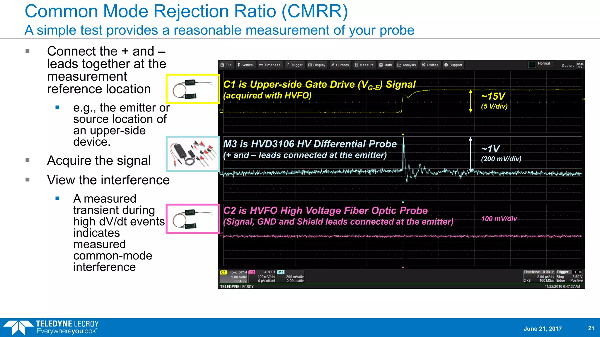
21.
Common Mode RejectionRatio (CMRR)
A simple test provides a reasonable measurement of your probe
Connect the + and –
leads together at the
measurement
reference location
e.g., the emitter or
source location of
an upper-side
device.
Acquire the signal
View the interference
A measured
transient during
high dV/dt events
indicates
measured
common-mode
interference
C2 is HVFO High Voltage Fiber Optic Probe
(Signal, GND and Shield leads connected at the emitter)
C1 is Upper-side Gate Drive (VG-E) Signal
(acquired with HVFO)
M3 is HVD3106 HV Differential Probe
(+ and – leads connected at the emitter)
~15V
(5 V/div)
~1V
(200 mV/div)
100 mV/div
June 21, 2017 21
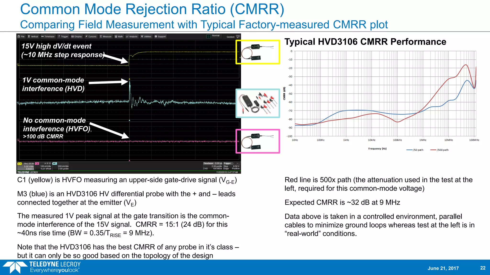
22.
Common Mode RejectionRatio (CMRR)
Comparing Field Measurement with Typical Factory-measured CMRR plot
Red line is 500x path (the attenuation used in the test at the
left, required for this common-mode voltage)
Expected CMRR is ~32 dB at 9 MHz
Data above is taken in a controlled environment, parallel
cables to minimize ground loops whereas test at the left is in
“real-world” conditions.
Typical HVD3106 CMRR Performance
C1 (yellow) is HVFO measuring an upper-side gate-drive signal (VG-E)
M3 (blue) is an HVD3106 HV differential probe with the + and – leads
connected together at the emitter (VE)
The measured 1V peak signal at the gate transition is the common-
mode interference of the 15V signal. CMRR = 15:1 (24 dB) for this
~40ns rise time (BW = 0.35/TRISE = 9 MHz).
Note that the HVD3106 has the best CMRR of any probe in it’s class –
but it can only be so good based on the topology of the design
No common-mode
interference (HVFO),
>100 dB CMRR
1V common-mode
interference (HVD)
15V high dV/dt event
(~10 MHz step response)
June 21, 2017 22
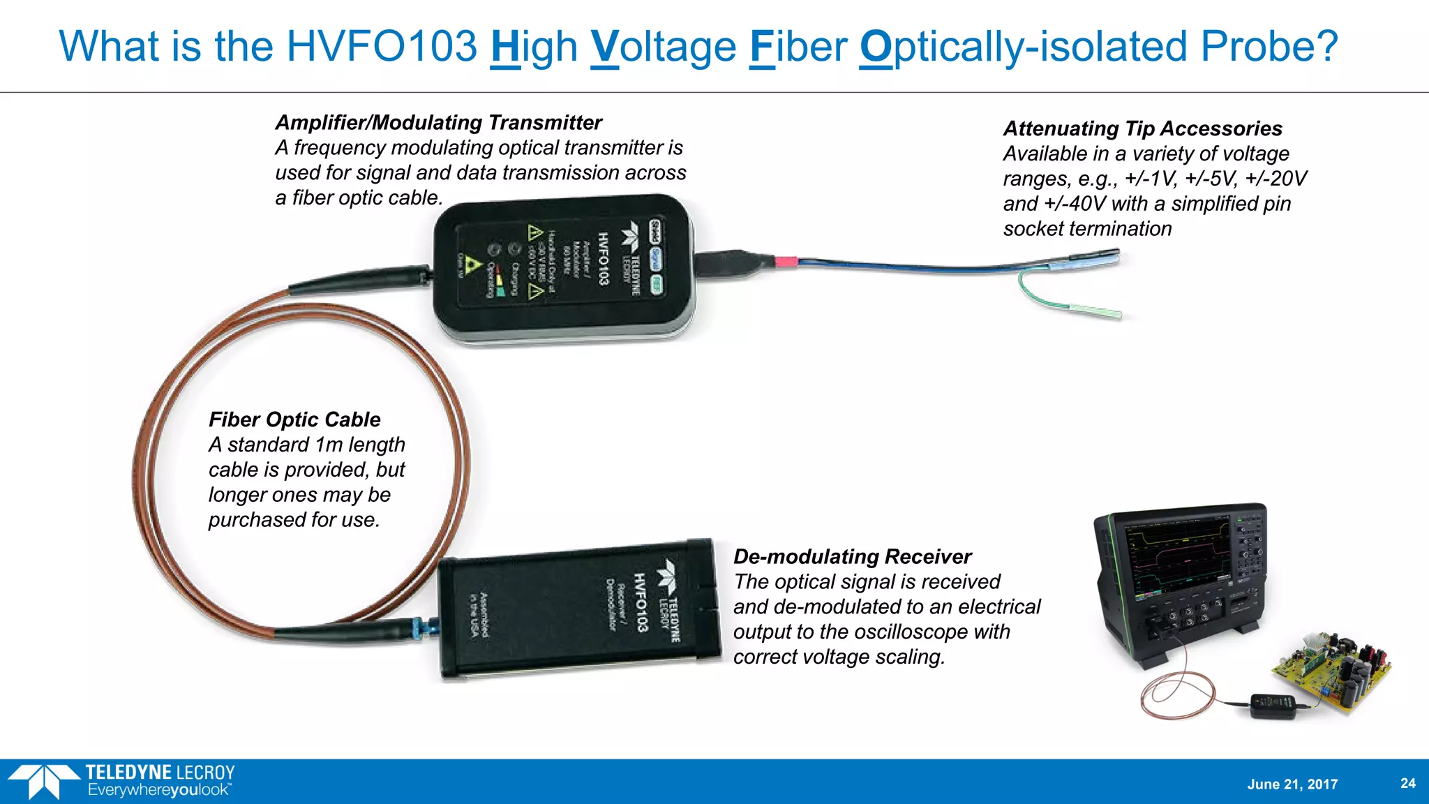
What is theHVFO103 High Voltage Fiber Optically-isolated Probe?
Amplifier/Modulating Transmitter
A frequency modulating optical transmitter is
used for signal and data transmission across
a fiber optic cable.
De-modulating Receiver
The optical signal is received
and de-modulated to an electrical
output to the oscilloscope with
correct voltage scaling.
Fiber Optic Cable
A standard 1m length
cable is provided, but
longer ones may be
purchased for use.
Attenuating Tip Accessories
Available in a variety of voltage
ranges, e.g., +/-1V, +/-5V, +/-20V
and +/-40V with a simplified pin
socket termination
June 21, 2017 24
25.
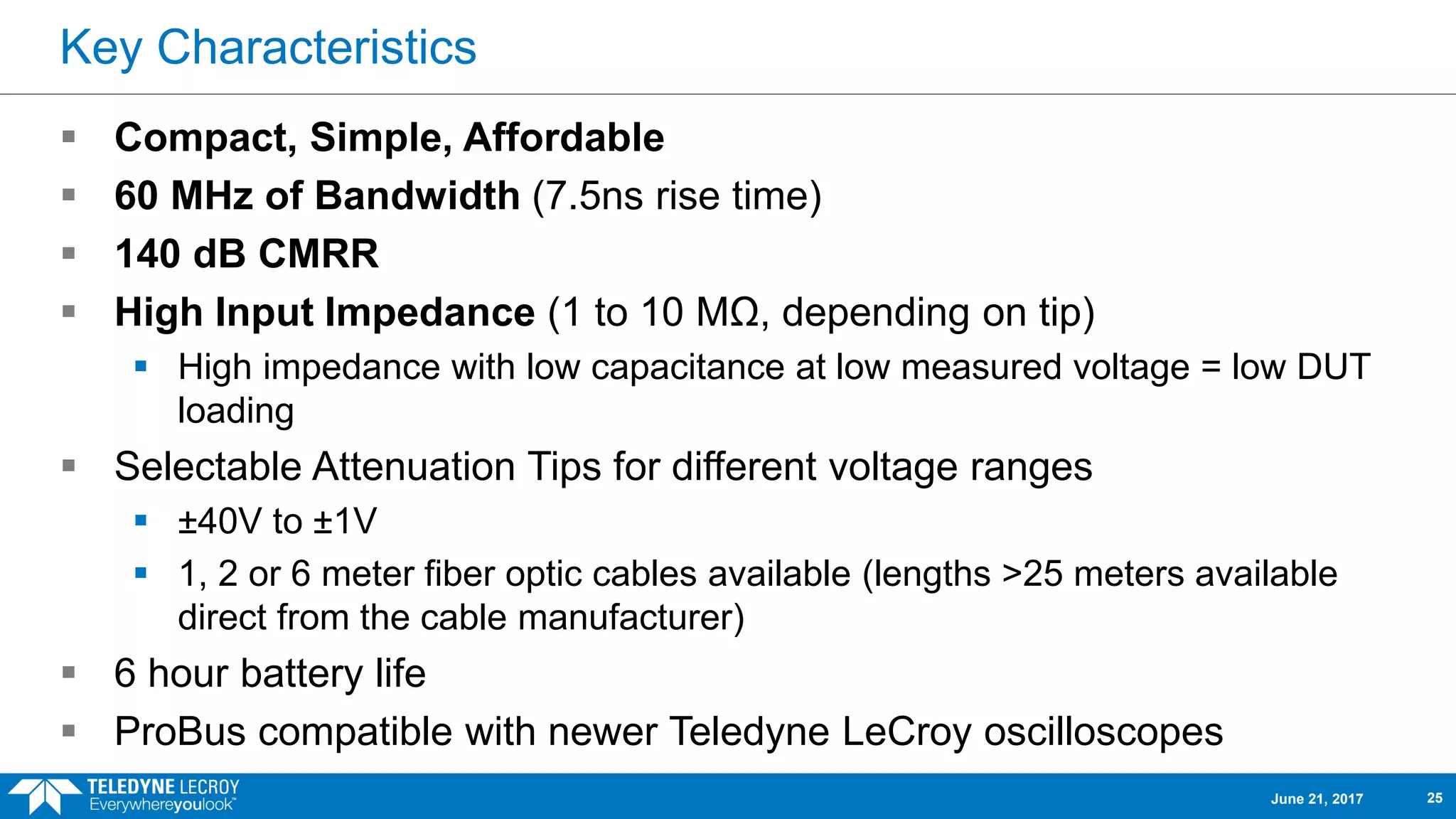
Key Characteristics
Compact,Simple, Affordable
60 MHz of Bandwidth (7.5ns rise time)
140 dB CMRR
High Input Impedance (1 to 10 MΩ, depending on tip)
High impedance with low capacitance at low measured voltage = low DUT
loading
Selectable Attenuation Tips for different voltage ranges
±40V to ±1V
1, 2 or 6 meter fiber optic cables available (lengths >25 meters available
direct from the cable manufacturer)
6 hour battery life
ProBus compatible with newer Teledyne LeCroy oscilloscopes
June 21, 2017 25
26.
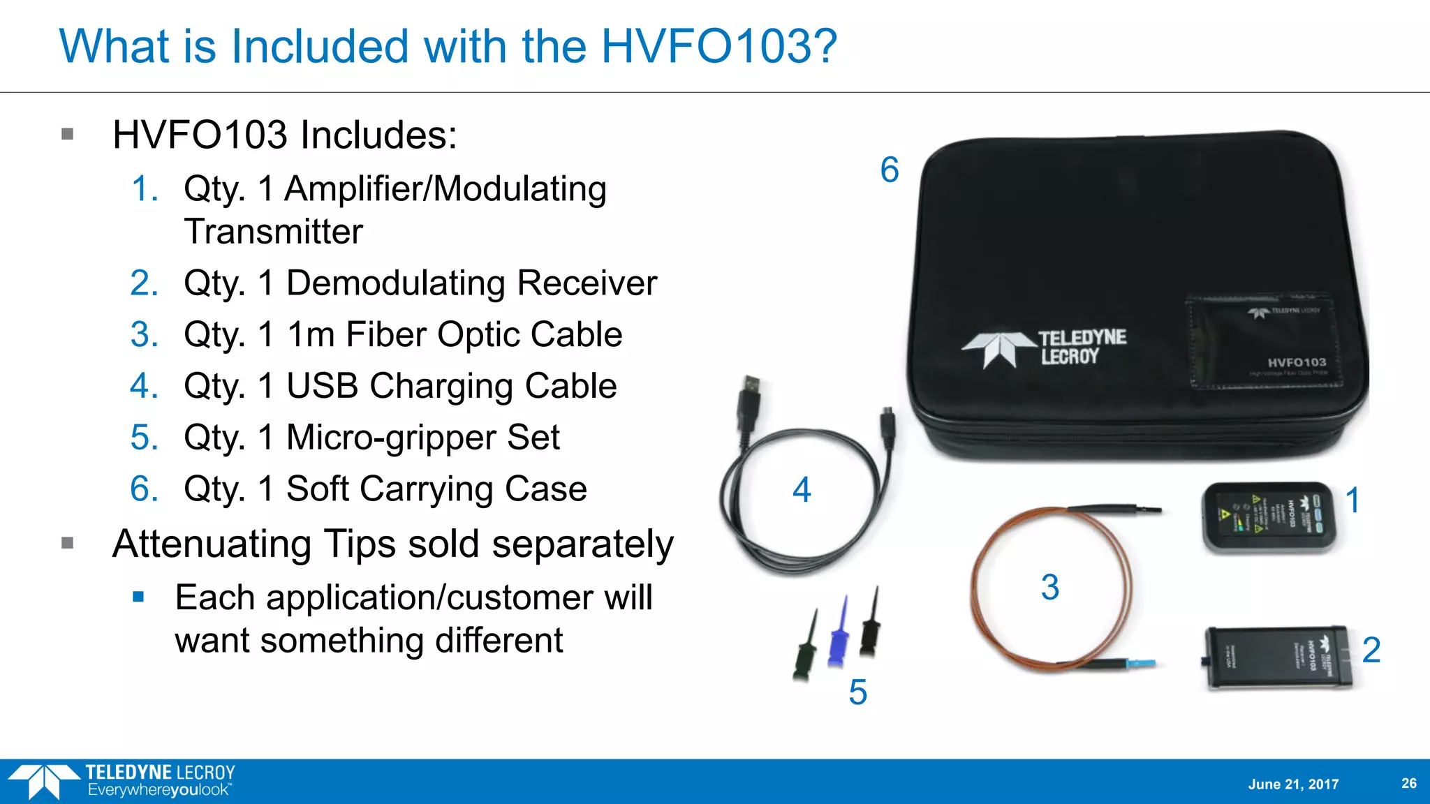
What is Includedwith the HVFO103?
HVFO103 Includes:
1. Qty. 1 Amplifier/Modulating
Transmitter
2. Qty. 1 Demodulating Receiver
3. Qty. 1 1m Fiber Optic Cable
4. Qty. 1 USB Charging Cable
5. Qty. 1 Micro-gripper Set
6. Qty. 1 Soft Carrying Case
Attenuating Tips sold separately
Each application/customer will
want something different
1
2
4
5
3
6
June 21, 2017 26
27.
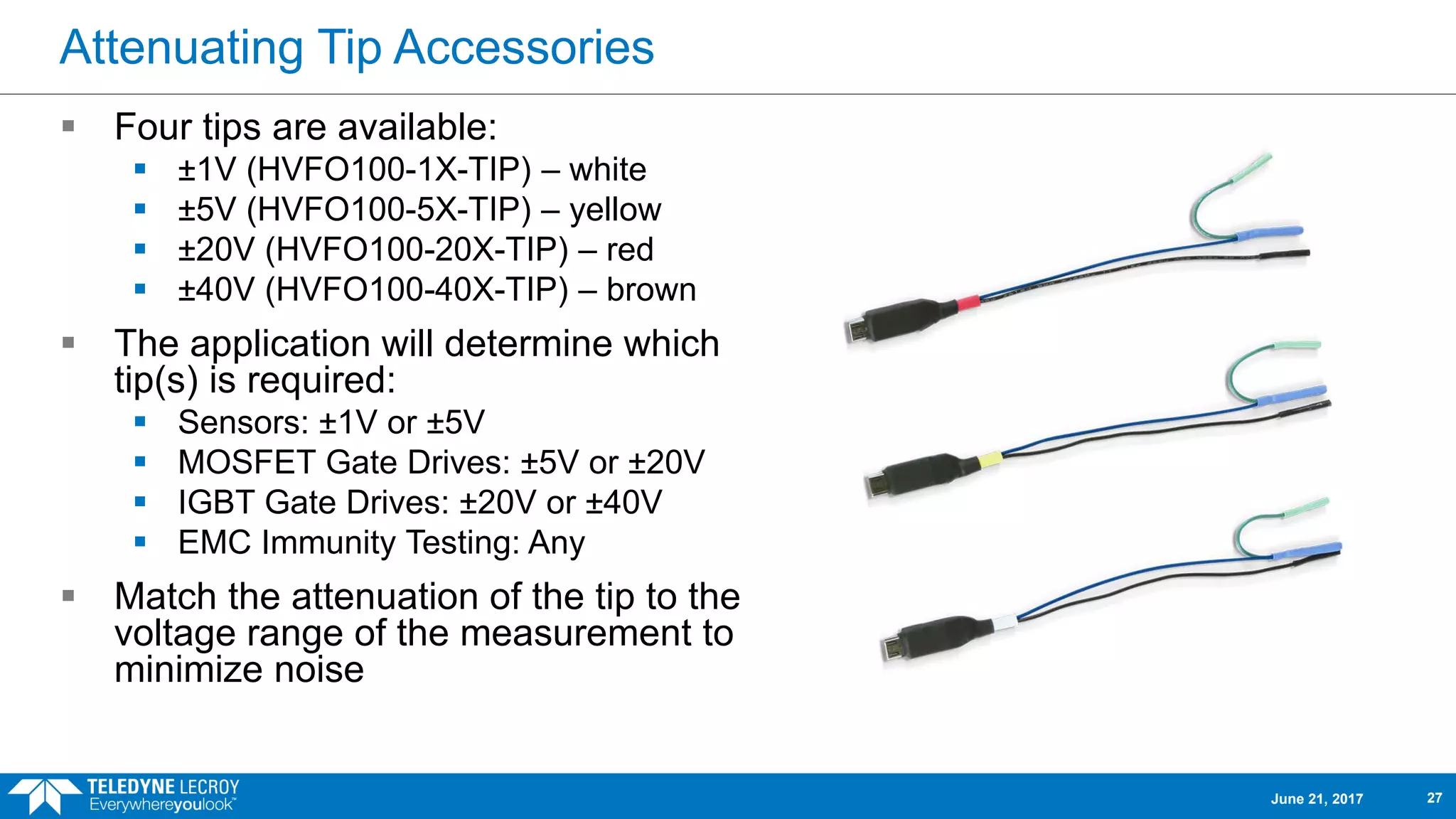
Attenuating Tip Accessories
Four tips are available:
±1V (HVFO100-1X-TIP) – white
±5V (HVFO100-5X-TIP) – yellow
±20V (HVFO100-20X-TIP) – red
±40V (HVFO100-40X-TIP) – brown
The application will determine which
tip(s) is required:
Sensors: ±1V or ±5V
MOSFET Gate Drives: ±5V or ±20V
IGBT Gate Drives: ±20V or ±40V
EMC Immunity Testing: Any
Match the attenuation of the tip to the
voltage range of the measurement to
minimize noise
June 21, 2017 27
28.
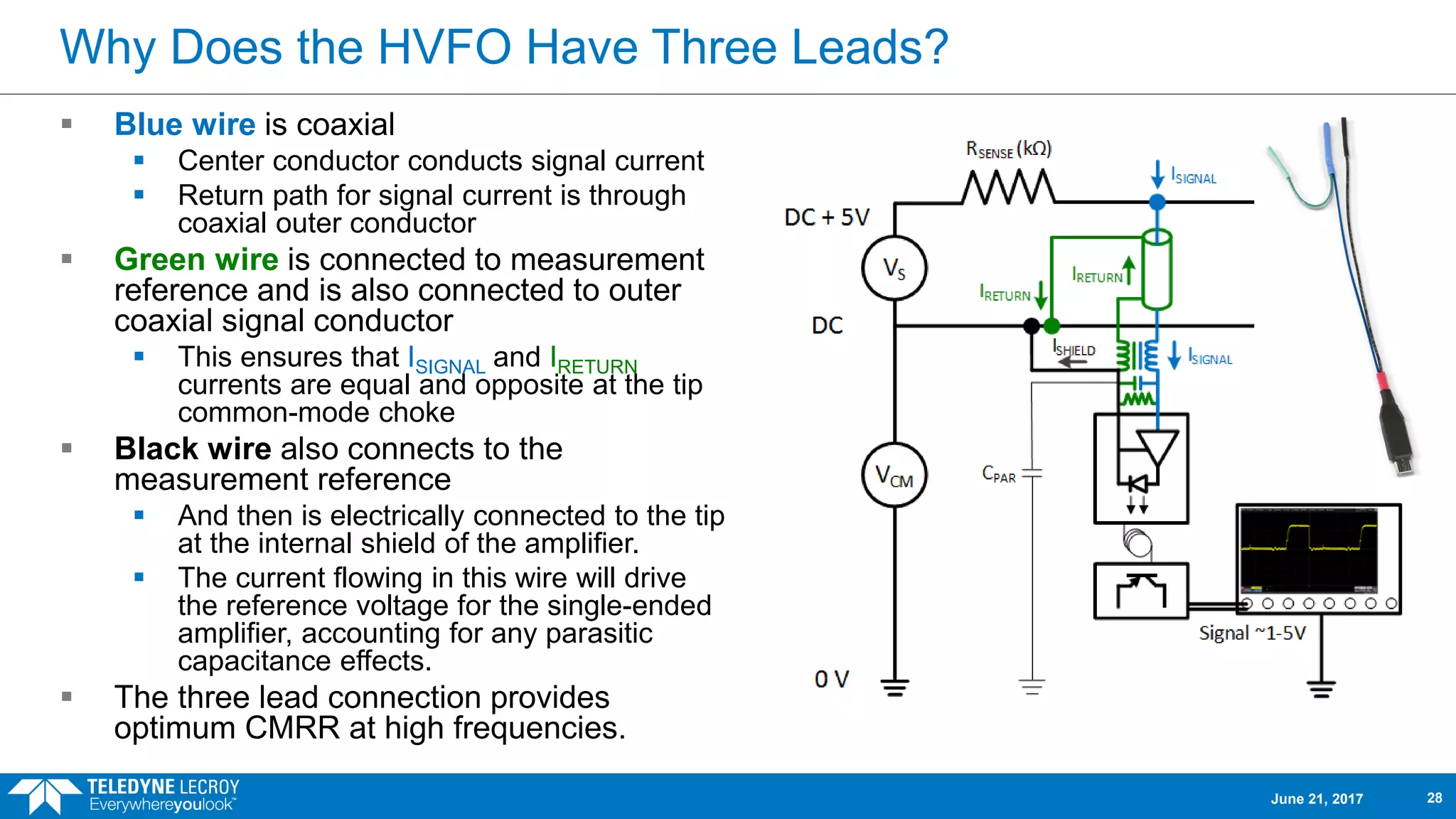
Why Does theHVFO Have Three Leads?
Blue wire is coaxial
Center conductor conducts signal current
Return path for signal current is through
coaxial outer conductor
Green wire is connected to measurement
reference and is also connected to outer
coaxial signal conductor
This ensures that ISIGNAL and IRETURN
currents are equal and opposite at the tip
common-mode choke
Black wire also connects to the
measurement reference
And then is electrically connected to the tip
at the internal shield of the amplifier.
The current flowing in this wire will drive
the reference voltage for the single-ended
amplifier, accounting for any parasitic
capacitance effects.
The three lead connection provides
optimum CMRR at high frequencies.
June 21, 2017 28
29.
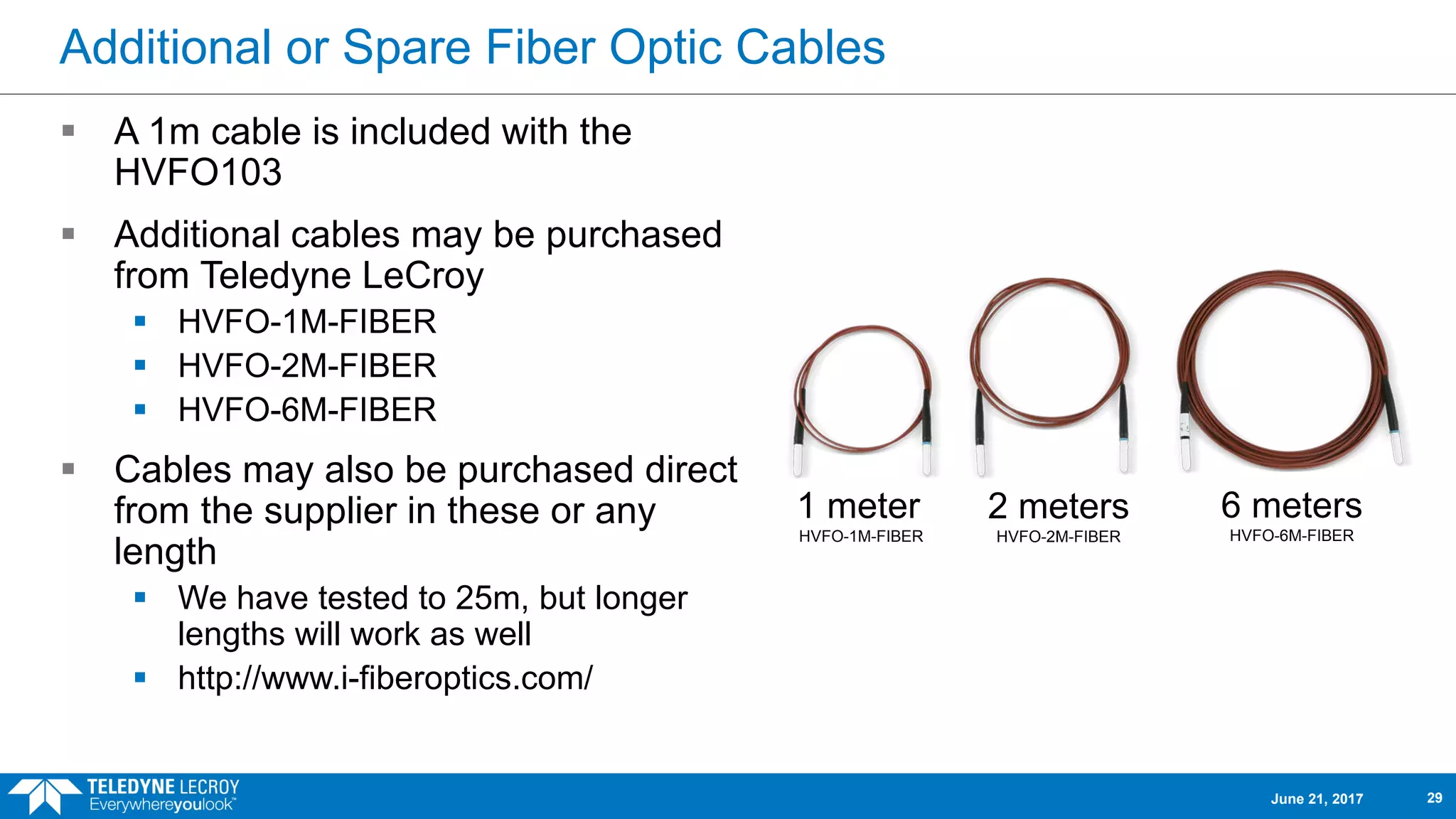
Additional or SpareFiber Optic Cables
A 1m cable is included with the
HVFO103
Additional cables may be purchased
from Teledyne LeCroy
HVFO-1M-FIBER
HVFO-2M-FIBER
HVFO-6M-FIBER
Cables may also be purchased direct
from the supplier in these or any
length
We have tested to 25m, but longer
lengths will work as well
http://www.i-fiberoptics.com/
1 meter
HVFO-1M-FIBER
2 meters
HVFO-2M-FIBER
6 meters
HVFO-6M-FIBER
June 21, 2017 29
30.
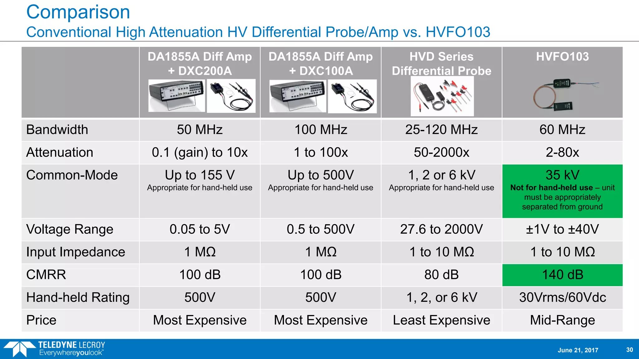
Comparison
Conventional High AttenuationHV Differential Probe/Amp vs. HVFO103
DA1855A Diff Amp
+ DXC200A
DA1855A Diff Amp
+ DXC100A
HVD Series
Differential Probe
HVFO103
Bandwidth 50 MHz 100 MHz 25-120 MHz 60 MHz
Attenuation 0.1 (gain) to 10x 1 to 100x 50-2000x 2-80x
Common-Mode Up to 155 V
Appropriate for hand-held use
Up to 500V
Appropriate for hand-held use
1, 2 or 6 kV
Appropriate for hand-held use
35 kV
Not for hand-held use – unit
must be appropriately
separated from ground
Voltage Range 0.05 to 5V 0.5 to 500V 27.6 to 2000V ±1V to ±40V
Input Impedance 1 MΩ 1 MΩ 1 to 10 MΩ 1 to 10 MΩ
CMRR 100 dB 100 dB 80 dB 140 dB
Hand-held Rating 500V 500V 1, 2, or 6 kV 30Vrms/60Vdc
Price Most Expensive Most Expensive Least Expensive Mid-Range
June 21, 2017 30
31.
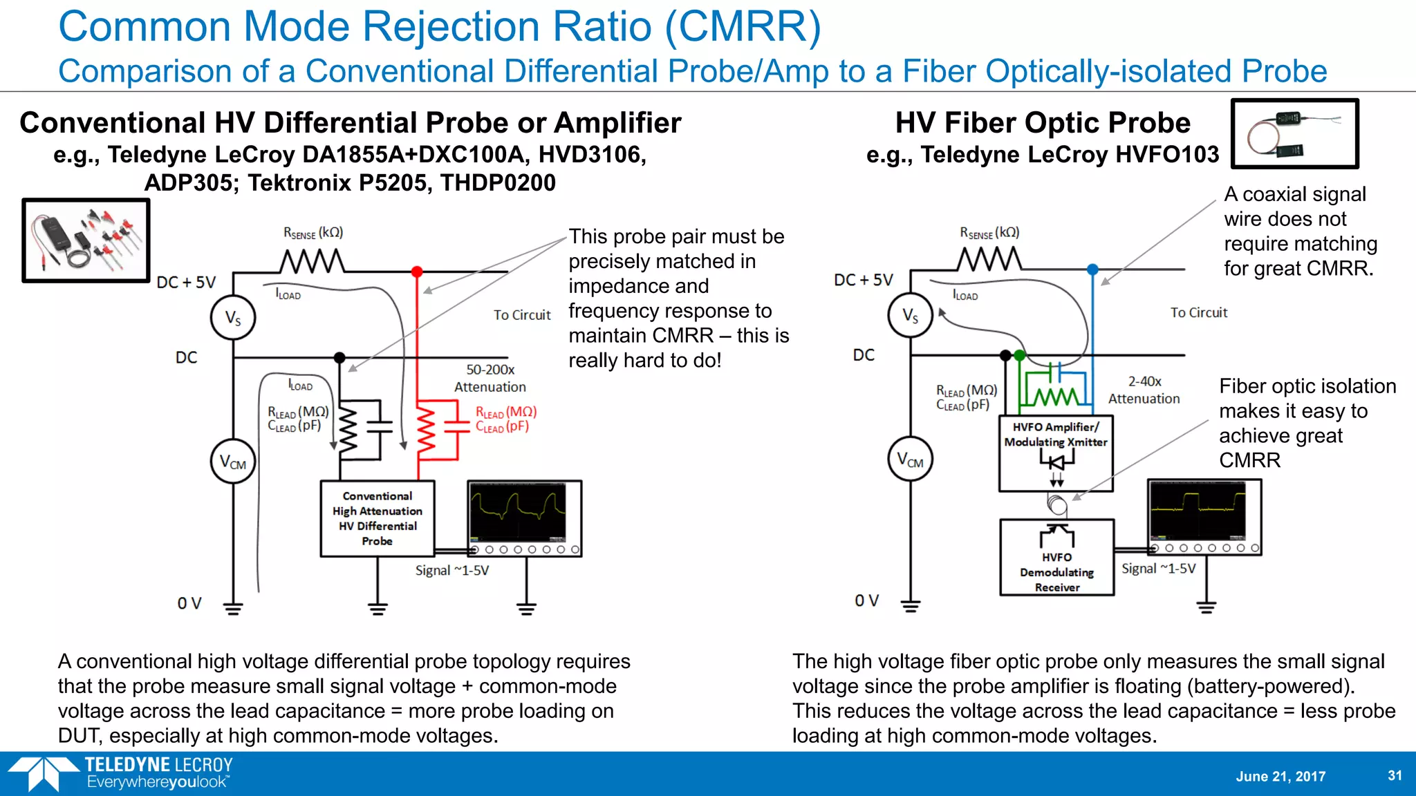
Common Mode RejectionRatio (CMRR)
Comparison of a Conventional Differential Probe/Amp to a Fiber Optically-isolated Probe
Conventional HV Differential Probe or Amplifier
e.g., Teledyne LeCroy DA1855A+DXC100A, HVD3106,
ADP305; Tektronix P5205, THDP0200
HV Fiber Optic Probe
e.g., Teledyne LeCroy HVFO103
A conventional high voltage differential probe topology requires
that the probe measure small signal voltage + common-mode
voltage across the lead capacitance = more probe loading on
DUT, especially at high common-mode voltages.
The high voltage fiber optic probe only measures the small signal
voltage since the probe amplifier is floating (battery-powered).
This reduces the voltage across the lead capacitance = less probe
loading at high common-mode voltages.
This probe pair must be
precisely matched in
impedance and
frequency response to
maintain CMRR – this is
really hard to do!
A coaxial signal
wire does not
require matching
for great CMRR.
Fiber optic isolation
makes it easy to
achieve great
CMRR
June 21, 2017 31
32.
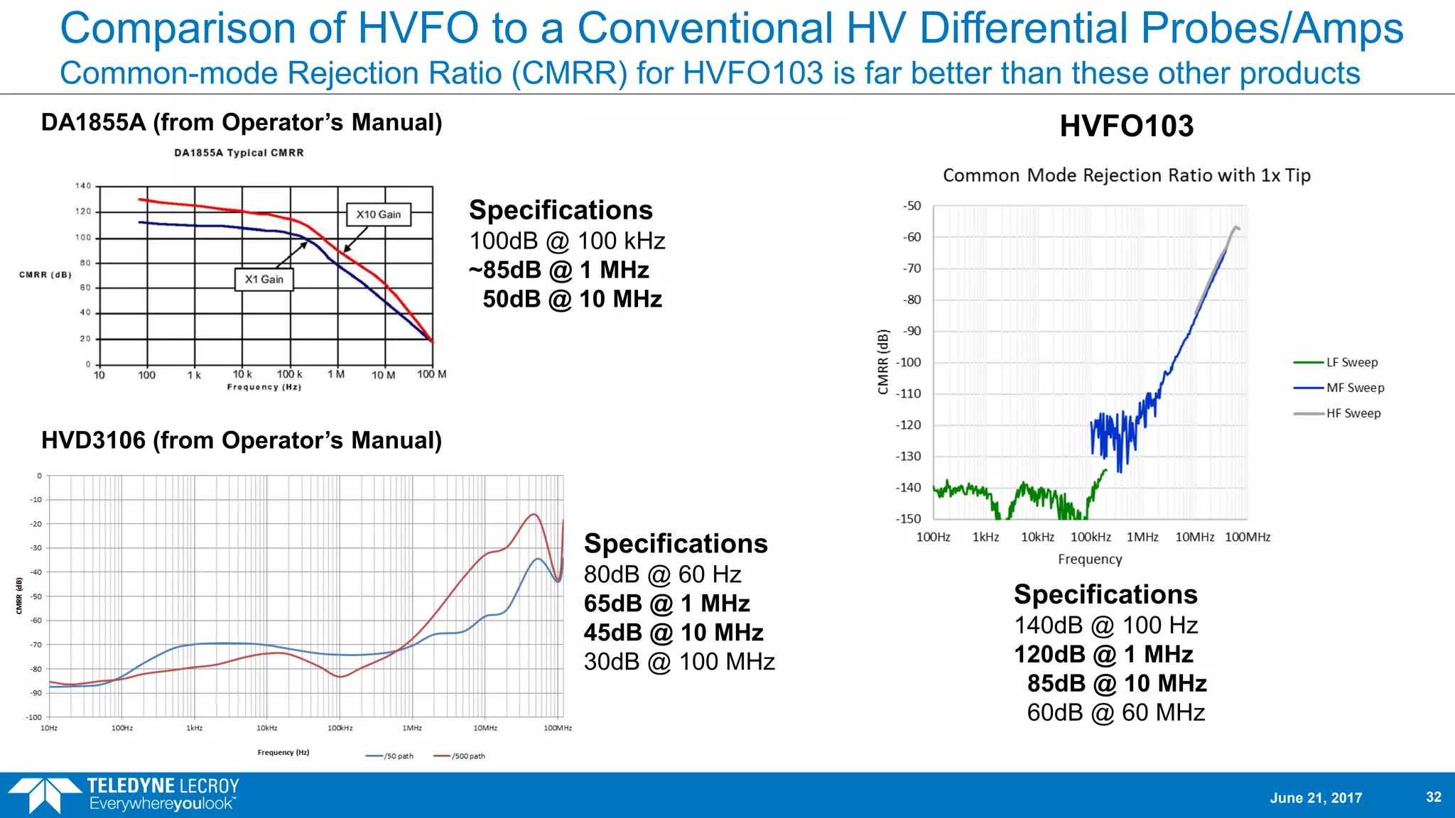
Comparison of HVFOto a Conventional HV Differential Probes/Amps
Common-mode Rejection Ratio (CMRR) for HVFO103 is far better than these other products
DA1855A (from Operator’s Manual) HVFO103
HVD3106 (from Operator’s Manual)
Specifications
80dB @ 60 Hz
65dB @ 1 MHz
45dB @ 10 MHz
30dB @ 100 MHz
Specifications
100dB @ 100 kHz
~85dB @ 1 MHz
50dB @ 10 MHz
Specifications
140dB @ 100 Hz
120dB @ 1 MHz
85dB @ 10 MHz
60dB @ 60 MHz
June 21, 2017 32
33.
Where is theHVFO103 needed and why?
There are a lot of different probes used in
power electronics testing. What niche is
filled by the HVFO103?
June 21, 2017 33
34.
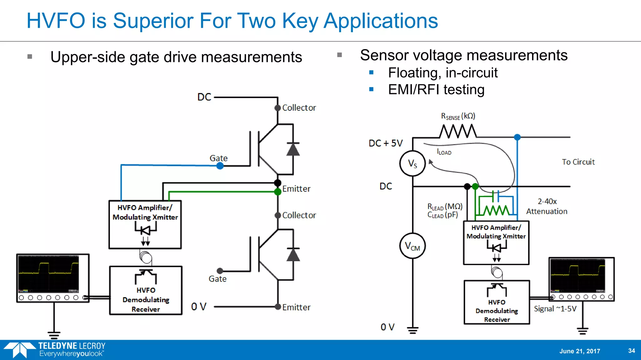
HVFO is SuperiorFor Two Key Applications
Upper-side gate drive measurements
June 21, 2017 34
Sensor voltage measurements
Floating, in-circuit
EMI/RFI testing
35.
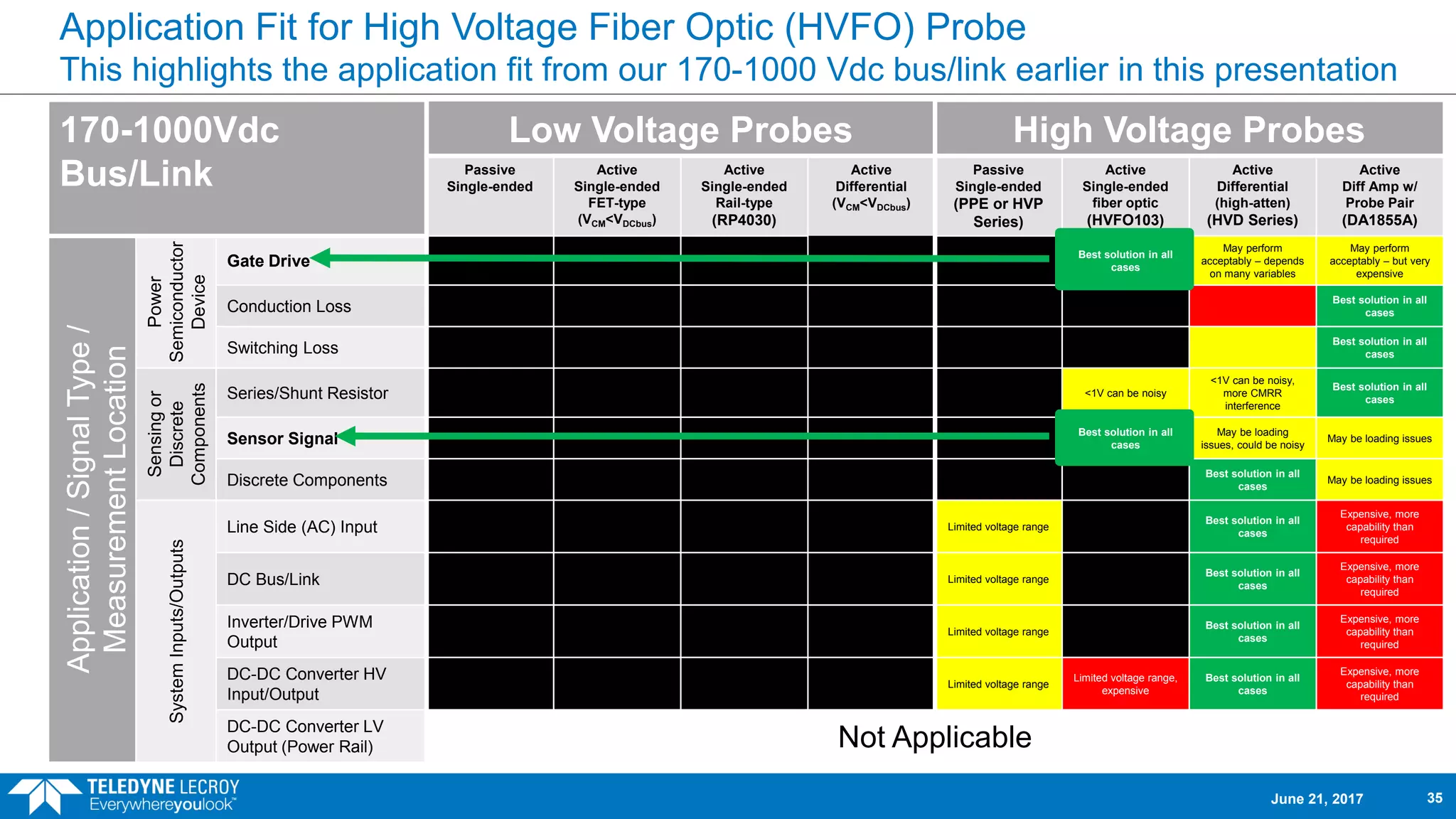
Application Fit forHigh Voltage Fiber Optic (HVFO) Probe
This highlights the application fit from our 170-1000 Vdc bus/link earlier in this presentation
170-1000Vdc
Bus/Link
Low Voltage Probes High Voltage Probes
Passive
Single-ended
Active
Single-ended
FET-type
(VCM<VDCbus)
Active
Single-ended
Rail-type
(RP4030)
Active
Differential
(VCM<VDCbus)
Passive
Single-ended
(PPE or HVP
Series)
Active
Single-ended
fiber optic
(HVFO103)
Active
Differential
(high-atten)
(HVD Series)
Active
Diff Amp w/
Probe Pair
(DA1855A)
Application/SignalType/
MeasurementLocation
Power
Semiconductor
Device
Gate Drive
Best solution in all
cases
May perform
acceptably – depends
on many variables
May perform
acceptably – but very
expensive
Conduction Loss
Best solution in all
cases
Switching Loss
Best solution in all
cases
Sensingor
Discrete
Components
Series/Shunt Resistor <1V can be noisy
<1V can be noisy,
more CMRR
interference
Best solution in all
cases
Sensor Signal
Best solution in all
cases
May be loading
issues, could be noisy
May be loading issues
Discrete Components
Best solution in all
cases
May be loading issues
SystemInputs/Outputs
Line Side (AC) Input Limited voltage range
Best solution in all
cases
Expensive, more
capability than
required
DC Bus/Link Limited voltage range
Best solution in all
cases
Expensive, more
capability than
required
Inverter/Drive PWM
Output
Limited voltage range
Best solution in all
cases
Expensive, more
capability than
required
DC-DC Converter HV
Input/Output
Limited voltage range
Limited voltage range,
expensive
Best solution in all
cases
Expensive, more
capability than
required
DC-DC Converter LV
Output (Power Rail) Not Applicable
June 21, 2017 35
36.
Comparison 1
Comparing theTeledyne LeCroy HVFO103 to a low-cost HV differential probe for
measurement of a SiC upper-side gate drive signal.
June 21, 2017 36
37.
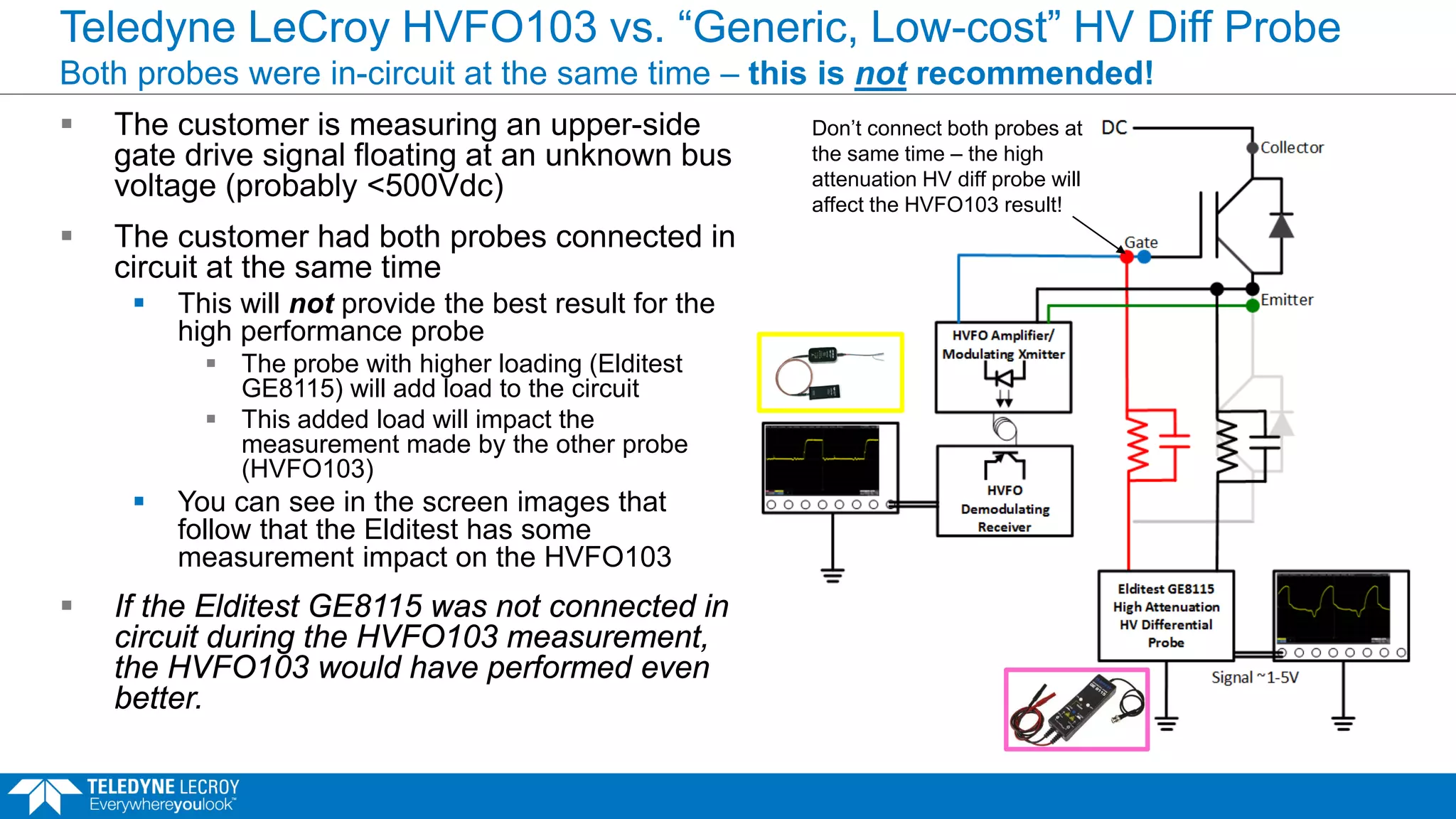
Teledyne LeCroy HVFO103vs. “Generic, Low-cost” HV Diff Probe
Both probes were in-circuit at the same time – this is not recommended!
The customer is measuring an upper-side
gate drive signal floating at an unknown bus
voltage (probably <500Vdc)
The customer had both probes connected in
circuit at the same time
This will not provide the best result for the
high performance probe
The probe with higher loading (Elditest
GE8115) will add load to the circuit
This added load will impact the
measurement made by the other probe
(HVFO103)
You can see in the screen images that
follow that the Elditest has some
measurement impact on the HVFO103
If the Elditest GE8115 was not connected in
circuit during the HVFO103 measurement,
the HVFO103 would have performed even
better.
Don’t connect both probes at
the same time – the high
attenuation HV diff probe will
affect the HVFO103 result!
38.
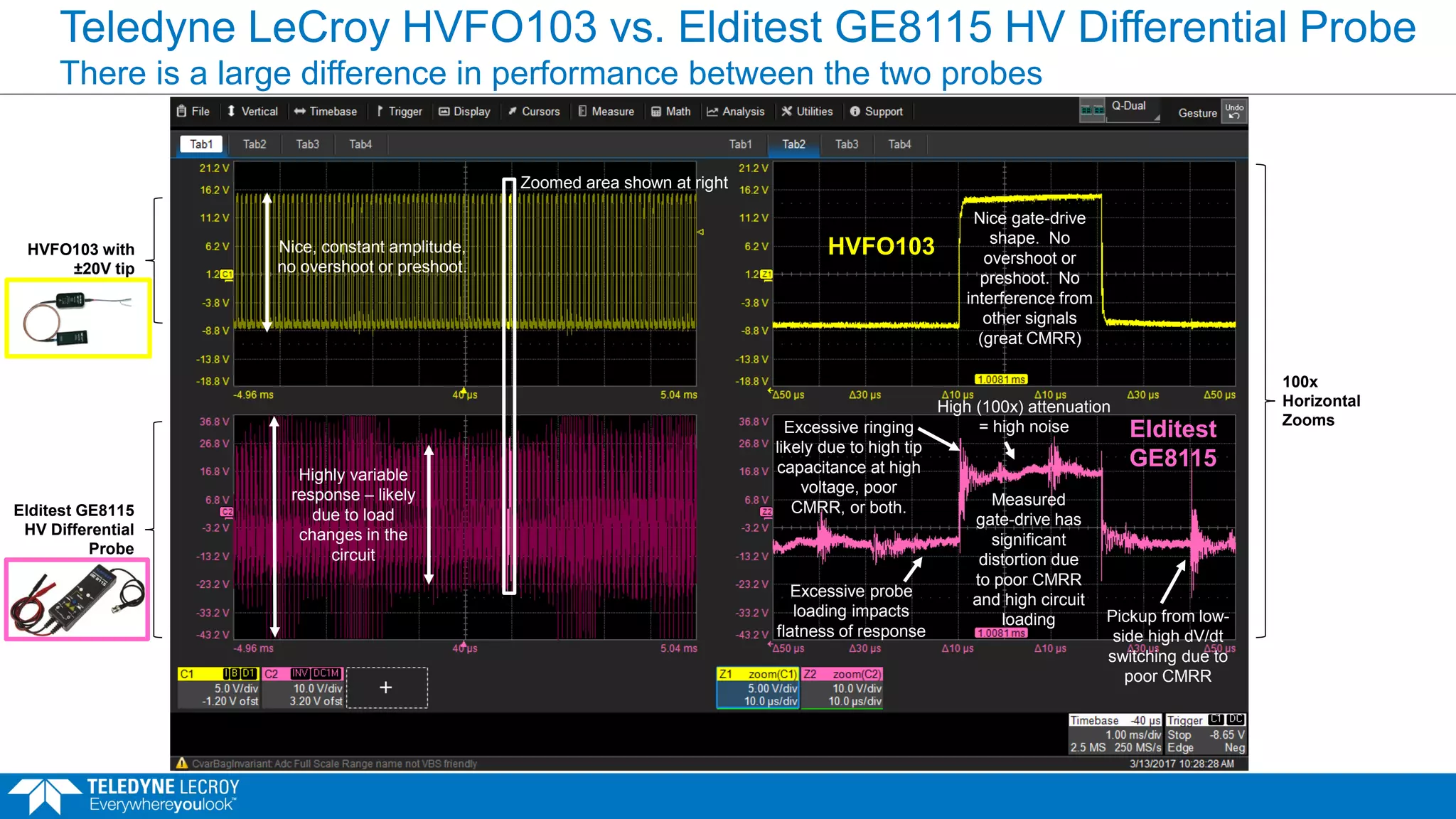
Teledyne LeCroy HVFO103vs. Elditest GE8115 HV Differential Probe
There is a large difference in performance between the two probes
HVFO103 with
±20V tip
Elditest GE8115
HV Differential
Probe
Zoomed area shown at right
100x
Horizontal
Zooms
Nice gate-drive
shape. No
overshoot or
preshoot. No
interference from
other signals
(great CMRR)
Measured
gate-drive has
significant
distortion due
to poor CMRR
and high circuit
loading Pickup from low-
side high dV/dt
switching due to
poor CMRR
Excessive probe
loading impacts
flatness of response
Excessive ringing
likely due to high tip
capacitance at high
voltage, poor
CMRR, or both.
Elditest
GE8115
HVFO103
High (100x) attenuation
= high noise
Nice, constant amplitude,
no overshoot or preshoot.
Highly variable
response – likely
due to load
changes in the
circuit
39.
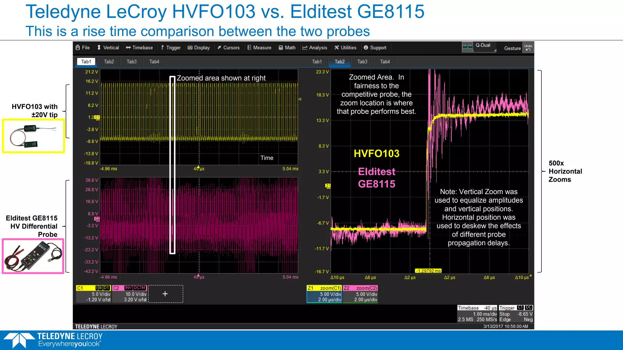
Teledyne LeCroy HVFO103vs. Elditest GE8115
This is a rise time comparison between the two probes
HVFO103 with
±20V tip
Time
Efficiency
Zoomed Area. In
fairness to the
competitive probe, the
zoom location is where
that probe performs best.
Note: Vertical Zoom was
used to equalize amplitudes
and vertical positions.
Horizontal position was
used to deskew the effects
of different probe
propagation delays.
Zoomed area shown at right
500x
Horizontal
Zooms
Elditest
GE8115
HVFO103
Elditest GE8115
HV Differential
Probe
40.
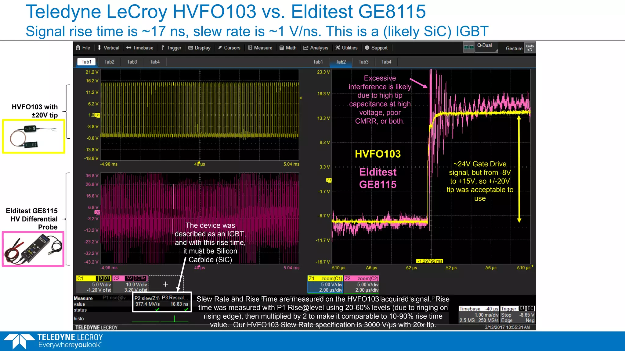
Teledyne LeCroy HVFO103vs. Elditest GE8115
Signal rise time is ~17 ns, slew rate is ~1 V/ns. This is a (likely SiC) IGBT
Slew Rate and Rise Time are measured on the HVFO103 acquired signal. Rise
time was measured with P1 Rise@level using 20-60% levels (due to ringing on
rising edge), then multiplied by 2 to make it comparable to 10-90% rise time
value. Our HVFO103 Slew Rate specification is 3000 V/μs with 20x tip.
The device was
described as an IGBT,
and with this rise time,
it must be Silicon
Carbide (SiC)
Excessive
interference is likely
due to high tip
capacitance at high
voltage, poor
CMRR, or both.
Elditest
GE8115
HVFO103
~24V Gate Drive
signal, but from -8V
to +15V, so +/-20V
tip was acceptable to
use
HVFO103 with
±20V tip
Elditest GE8115
HV Differential
Probe
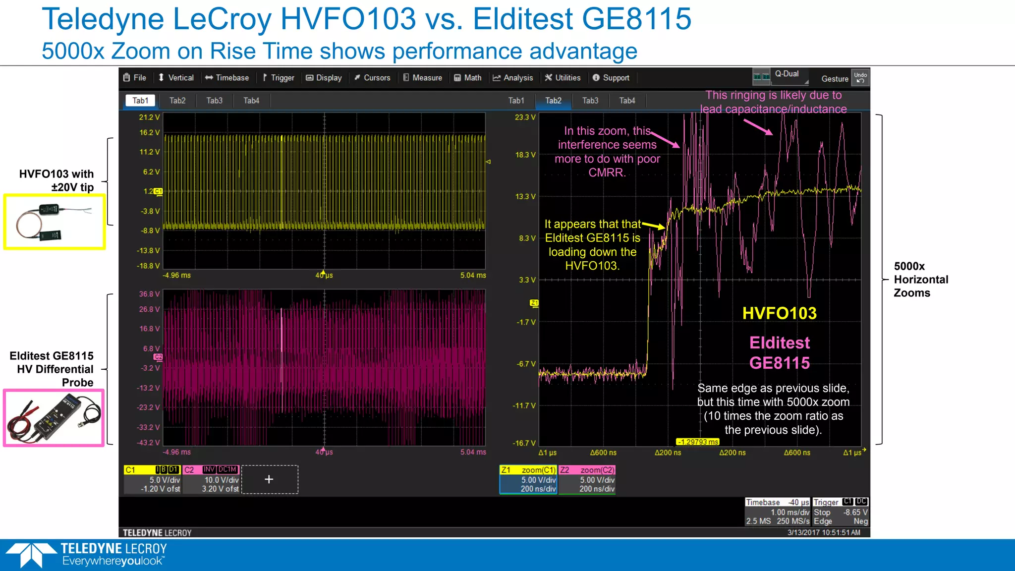
41.
Teledyne LeCroy HVFO103vs. Elditest GE8115
5000x Zoom on Rise Time shows performance advantage
5000x
Horizontal
Zooms
Same edge as previous slide,
but this time with 5000x zoom
(10 times the zoom ratio as
the previous slide).
Elditest
GE8115
HVFO103
In this zoom, this
interference seems
more to do with poor
CMRR.
It appears that that
Elditest GE8115 is
loading down the
HVFO103.
This ringing is likely due to
lead capacitance/inductance
HVFO103 with
±20V tip
Elditest GE8115
HV Differential
Probe
42.
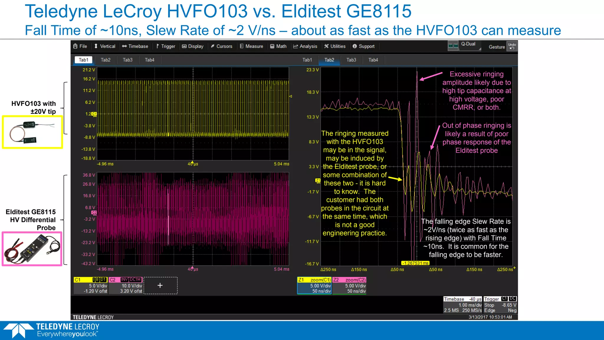
Teledyne LeCroy HVFO103vs. Elditest GE8115
Fall Time of ~10ns, Slew Rate of ~2 V/ns – about as fast as the HVFO103 can measure
Excessive ringing
amplitude likely due to
high tip capacitance at
high voltage, poor
CMRR, or both.
The ringing measured
with the HVFO103
may be in the signal,
may be induced by
the Elditest probe, or
some combination of
these two - it is hard
to know. The
customer had both
probes in the circuit at
the same time, which
is not a good
engineering practice.
Out of phase ringing is
likely a result of poor
phase response of the
Elditest probe
The falling edge Slew Rate is
~2V/ns (twice as fast as the
rising edge) with Fall Time
~10ns. It is common for the
falling edge to be faster.
HVFO103 with
±20V tip
Elditest GE8115
HV Differential
Probe
43.
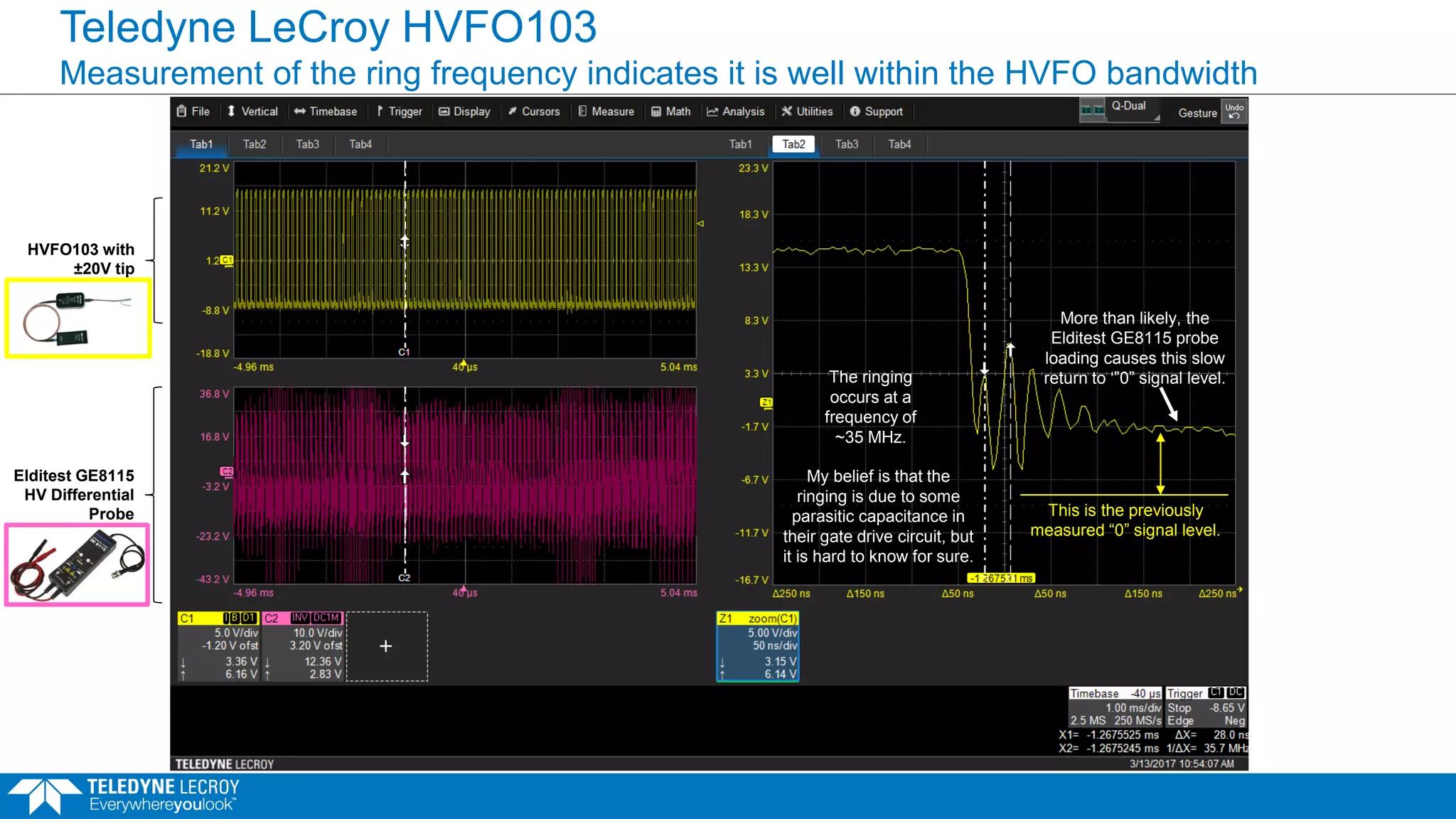
Teledyne LeCroy HVFO103
Measurementof the ring frequency indicates it is well within the HVFO bandwidth
The ringing
occurs at a
frequency of
~35 MHz.
My belief is that the
ringing is due to some
parasitic capacitance in
their gate drive circuit, but
it is hard to know for sure.
More than likely, the
Elditest GE8115 probe
loading causes this slow
return to ‘”0” signal level.
This is the previously
measured “0” signal level.
HVFO103 with
±20V tip
Elditest GE8115
HV Differential
Probe
44.
Comparison 2
Comparing theTeledyne LeCroy HVFO103 to a Teledyne LeCroy HVD3106 high voltage
differential probe and a DA1855A differential amplifier with DXC100A HV probe pair for
measurement of a Si upper-side gate drive signal.
June 21, 2017 44
45.
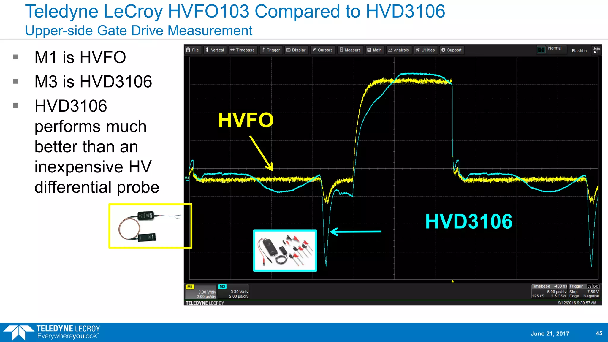
Teledyne LeCroy HVFO103Compared to HVD3106
Upper-side Gate Drive Measurement
HVFO
HVD3106
M1 is HVFO
M3 is HVD3106
HVD3106
performs much
better than an
inexpensive HV
differential probe
June 21, 2017 45
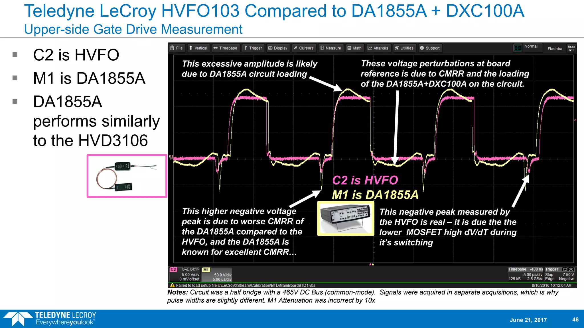
46.
Teledyne LeCroy HVFO103Compared to DA1855A + DXC100A
Upper-side Gate Drive Measurement
C2 is HVFO
M1 is DA1855A
DA1855A
performs similarly
to the HVD3106
Notes: Circuit was a half bridge with a 465V DC Bus (common-mode). Signals were acquired in separate acquisitions, which is why
pulse widths are slightly different. M1 Attenuation was incorrect by 10x
This higher negative voltage
peak is due to worse CMRR of
the DA1855A compared to the
HVFO, and the DA1855A is
known for excellent CMRR…
These voltage perturbations at board
reference is due to CMRR and the loading
of the DA1855A+DXC100A on the circuit.
This excessive amplitude is likely
due to DA1855A circuit loading
This negative peak measured by
the HVFO is real – it is due the the
lower MOSFET high dV/dT during
it’s switching
C2 is HVFO
M1 is DA1855A
June 21, 2017 46
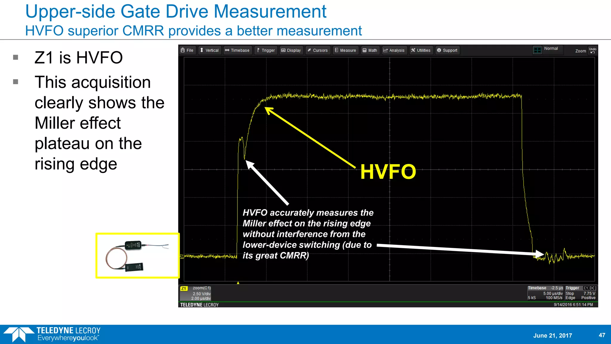
47.
Upper-side Gate DriveMeasurement
HVFO superior CMRR provides a better measurement
HVFO
Z1 is HVFO
This acquisition
clearly shows the
Miller effect
plateau on the
rising edge
HVFO accurately measures the
Miller effect on the rising edge
without interference from the
lower-device switching (due to
its great CMRR)
June 21, 2017 47
48.
Comparison 3
Comparing theTeledyne LeCroy HVFO103 to a Teledyne LeCroy ADP305 (older) and
HVD3106 (newer) high voltage differential probe, and a DA1855A differential amplifier with
DXC100A HV probe pair for measurement of an upper-side gate drive signal in an LED driver.
June 21, 2017 48
49.
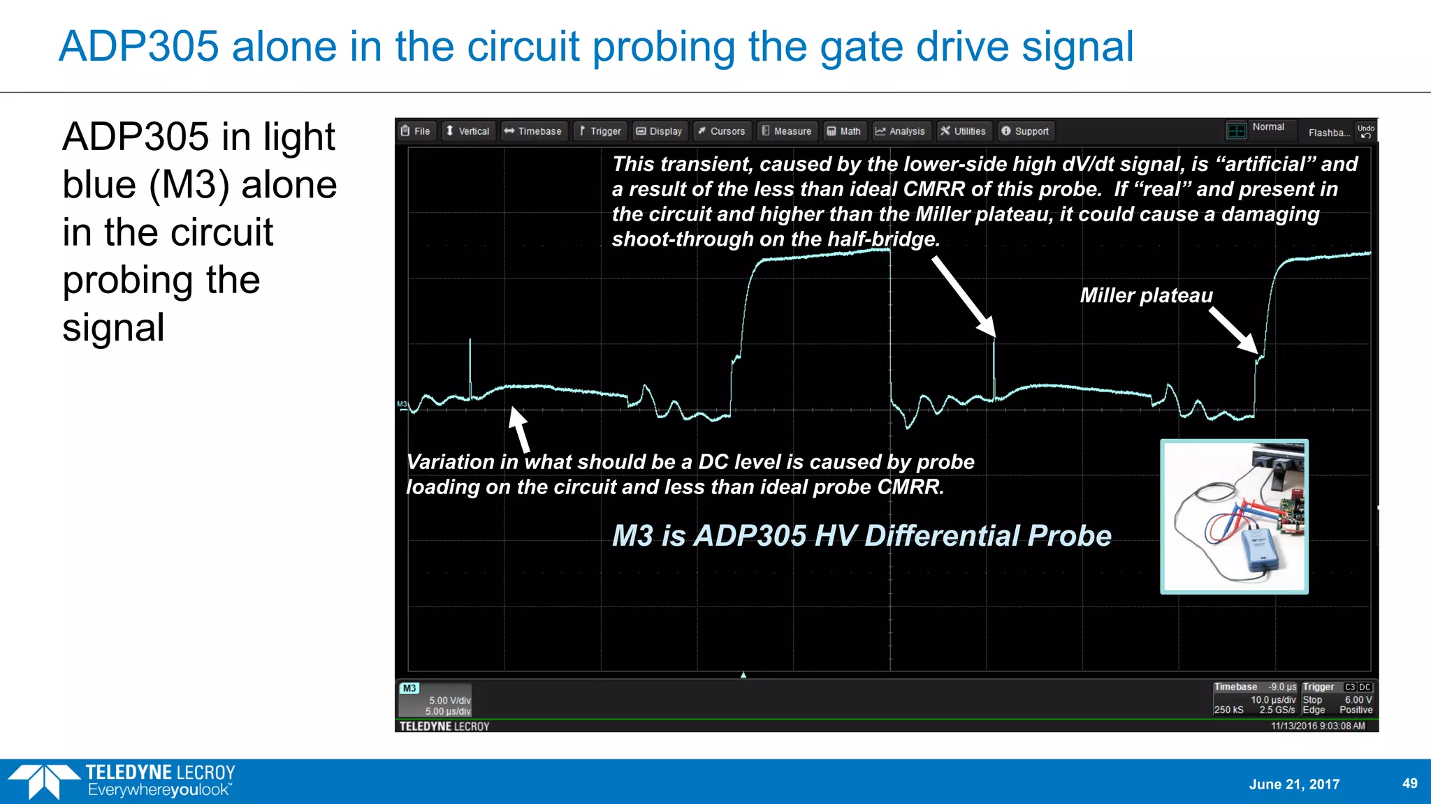
ADP305 alone inthe circuit probing the gate drive signal
ADP305 in light
blue (M3) alone
in the circuit
probing the
signal
M3 is ADP305 HV Differential Probe
This transient, caused by the lower-side high dV/dt signal, is “artificial” and
a result of the less than ideal CMRR of this probe. If “real” and present in
the circuit and higher than the Miller plateau, it could cause a damaging
shoot-through on the half-bridge.
Variation in what should be a DC level is caused by probe
loading on the circuit and less than ideal probe CMRR.
Miller plateau
June 21, 2017 49
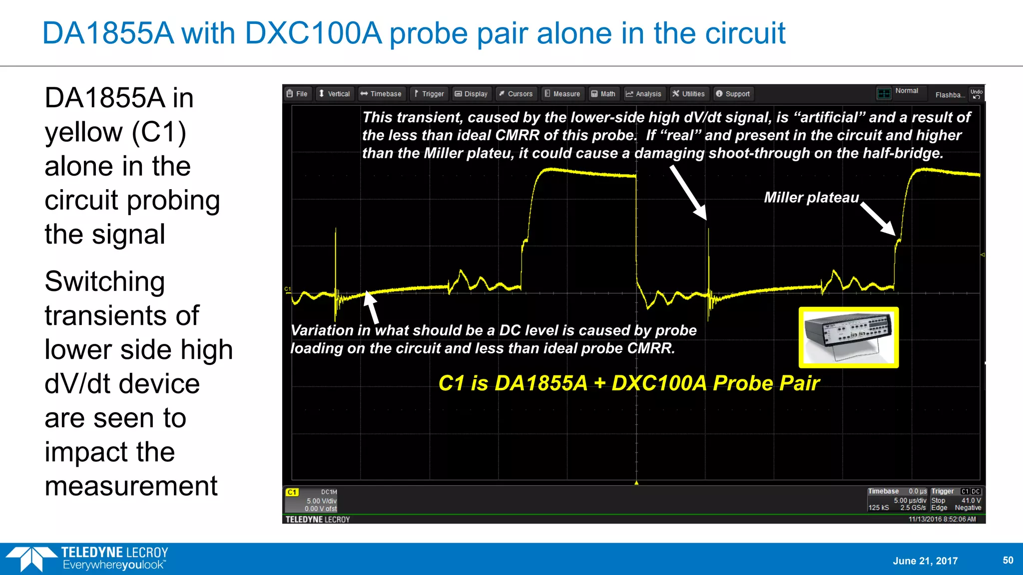
50.
DA1855A with DXC100Aprobe pair alone in the circuit
DA1855A in
yellow (C1)
alone in the
circuit probing
the signal
Switching
transients of
lower side high
dV/dt device
are seen to
impact the
measurement
C1 is DA1855A + DXC100A Probe Pair
This transient, caused by the lower-side high dV/dt signal, is “artificial” and a result of
the less than ideal CMRR of this probe. If “real” and present in the circuit and higher
than the Miller plateu, it could cause a damaging shoot-through on the half-bridge.
Variation in what should be a DC level is caused by probe
loading on the circuit and less than ideal probe CMRR.
Miller plateau
June 21, 2017 50
51.
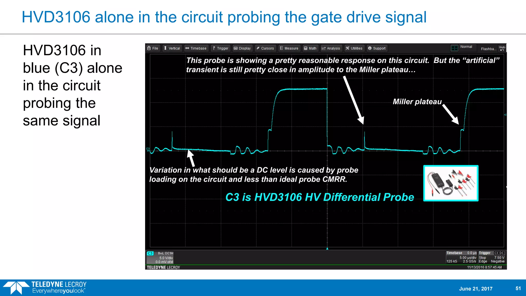
HVD3106 alone inthe circuit probing the gate drive signal
HVD3106 in
blue (C3) alone
in the circuit
probing the
same signal
C3 is HVD3106 HV Differential Probe
This probe is showing a pretty reasonable response on this circuit. But the “artificial”
transient is still pretty close in amplitude to the Miller plateau…
Miller plateau
Variation in what should be a DC level is caused by probe
loading on the circuit and less than ideal probe CMRR.
June 21, 2017 51
52.
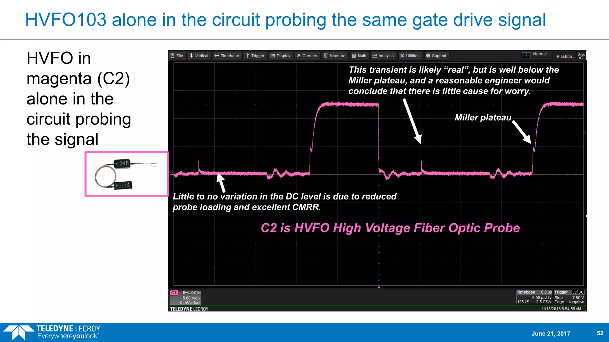
HVFO103 alone inthe circuit probing the same gate drive signal
HVFO in
magenta (C2)
alone in the
circuit probing
the signal
C2 is HVFO High Voltage Fiber Optic Probe
This transient is likely “real”, but is well below the
Miller plateau, and a reasonable engineer would
conclude that there is little cause for worry.
Miller plateau
Little to no variation in the DC level is due to reduced
probe loading and excellent CMRR.
June 21, 2017 52
53.
Comparison 4
Comparing theTeledyne LeCroy HVFO103 to a Teledyne LeCroy HVD3106 high voltage
differential probe for measurement of a floating sensor signal
June 21, 2017 53
54.
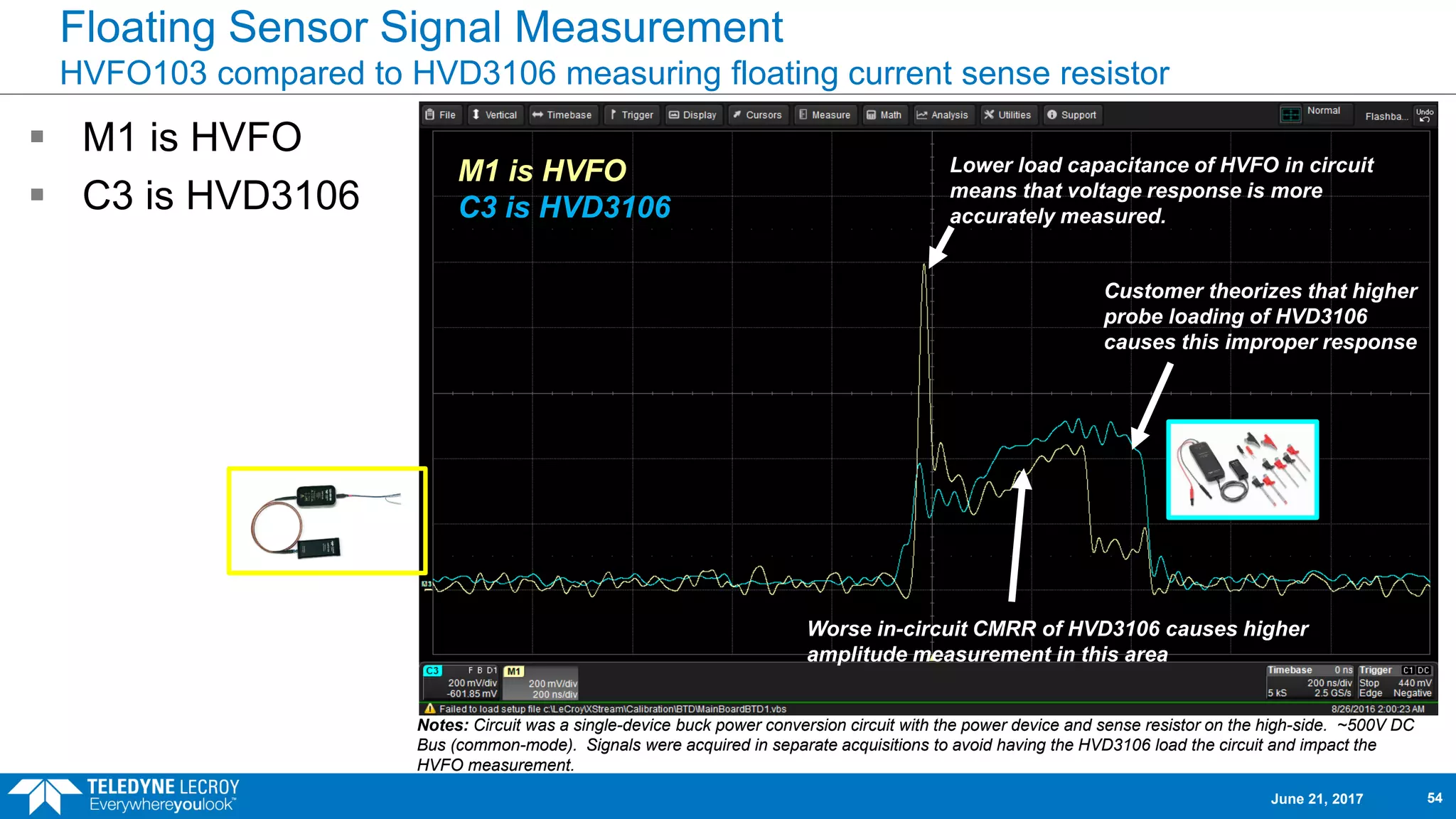
Floating Sensor SignalMeasurement
HVFO103 compared to HVD3106 measuring floating current sense resistor
M1 is HVFO
C3 is HVD3106
Notes: Circuit was a single-device buck power conversion circuit with the power device and sense resistor on the high-side. ~500V DC
Bus (common-mode). Signals were acquired in separate acquisitions to avoid having the HVD3106 load the circuit and impact the
HVFO measurement.
Customer theorizes that higher
probe loading of HVD3106
causes this improper response
Lower load capacitance of HVFO in circuit
means that voltage response is more
accurately measured.
Worse in-circuit CMRR of HVD3106 causes higher
amplitude measurement in this area
M1 is HVFO
C3 is HVD3106
June 21, 2017 54
55.
Comparison 5
Comparing theTeledyne LeCroy HVFO103, HVD3106, and Passive Probe (for low
voltage signal) to 1kV isolated inputs with input leads.
June 21, 2017 55
56.
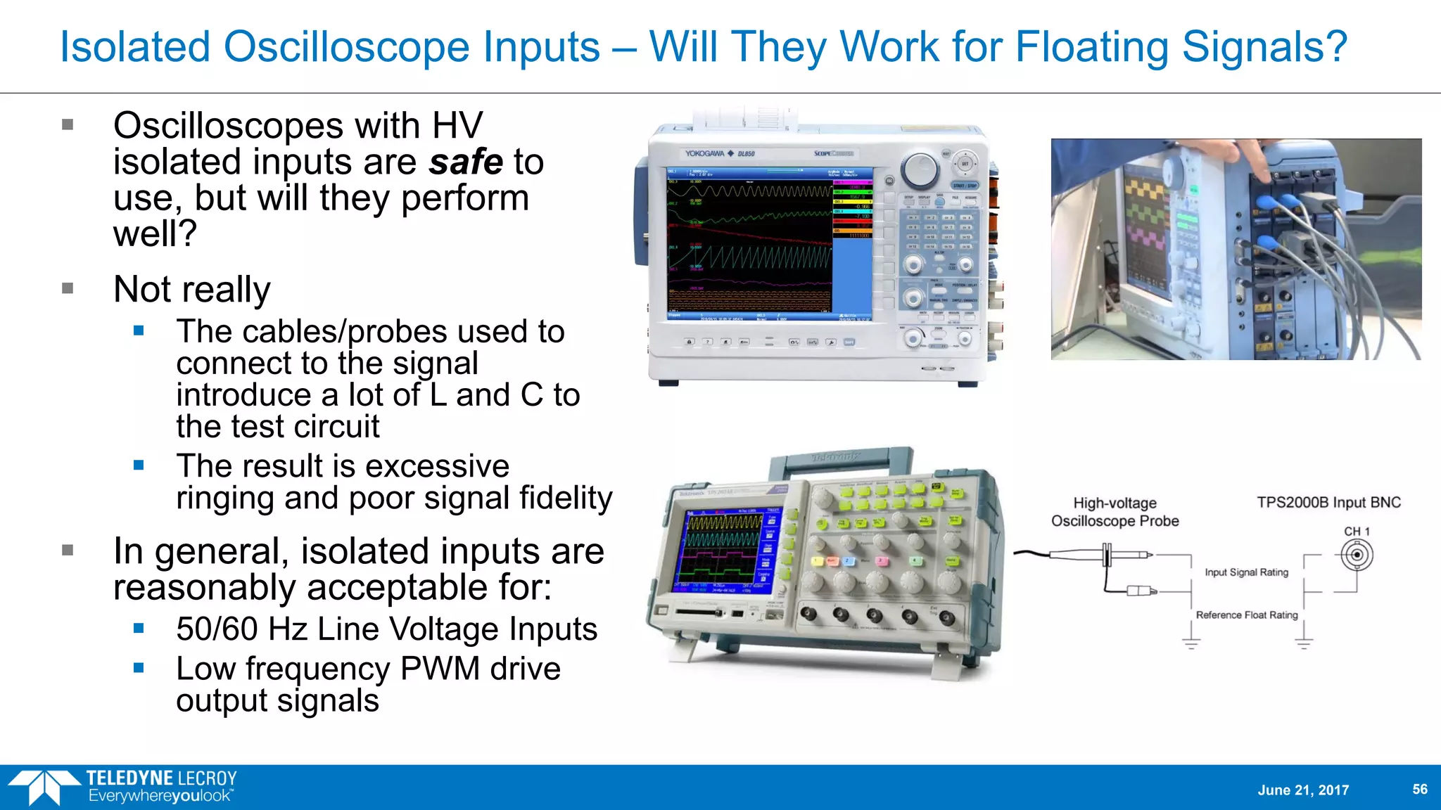
Isolated Oscilloscope Inputs– Will They Work for Floating Signals?
Oscilloscopes with HV
isolated inputs are safe to
use, but will they perform
well?
Not really
The cables/probes used to
connect to the signal
introduce a lot of L and C to
the test circuit
The result is excessive
ringing and poor signal fidelity
In general, isolated inputs are
reasonably acceptable for:
50/60 Hz Line Voltage Inputs
Low frequency PWM drive
output signals
June 21, 2017 56
57.
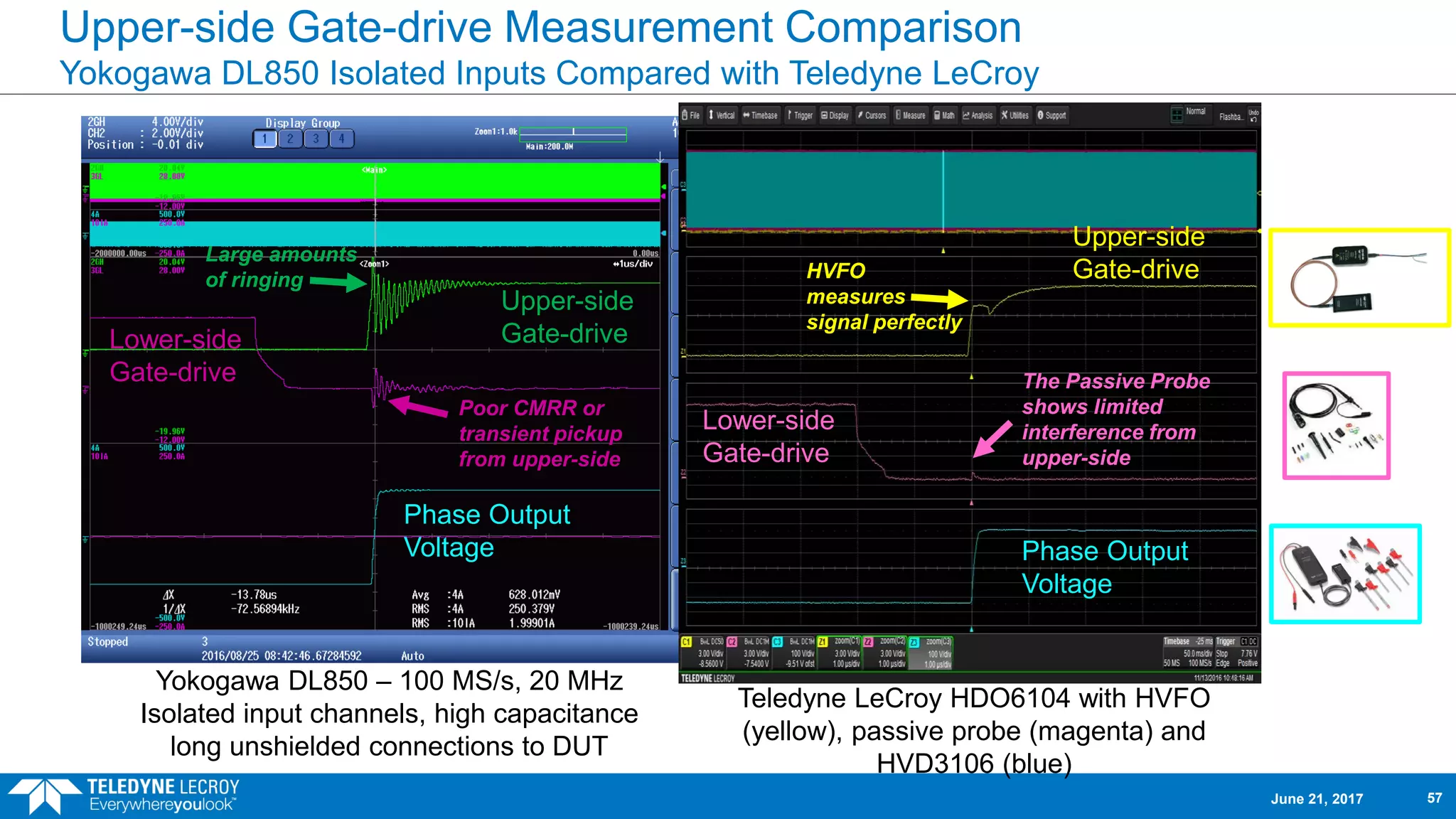
Upper-side Gate-drive MeasurementComparison
Yokogawa DL850 Isolated Inputs Compared with Teledyne LeCroy
Yokogawa DL850 – 100 MS/s, 20 MHz
Isolated input channels, high capacitance
long unshielded connections to DUT
Teledyne LeCroy HDO6104 with HVFO
(yellow), passive probe (magenta) and
HVD3106 (blue)
Upper-side
Gate-driveLower-side
Gate-drive
Phase Output
Voltage
Upper-side
Gate-drive
Lower-side
Gate-drive
Phase Output
Voltage
Large amounts
of ringing
Poor CMRR or
transient pickup
from upper-side
HVFO
measures
signal perfectly
The Passive Probe
shows limited
interference from
upper-side
June 21, 2017 57
58.
Polling Question #3
Have You Used an Oscilloscope With HV Isolated Inputs?
Yes
No
Don’t Know
June 21, 2017 58
The HVFO103 HighVoltage Fiber Optic Probe
Provides the capability to measure your signal as it truly is, in-circuit,
without compromise
Is Simple, Compact, and Affordable
Simple – a single laser and fiber optic cable for isolation and transmission.
Multiple tips achieve different operating voltage ranges
Compact - small enough to fit into tight spaces.
Affordable – fit the tightest of equipment budgets
Far surpasses the measurement capabilities and signal fidelity of both
conventional HV differential probes and acquisition systems that rely on
galvanic high voltage isolation
June 21, 2017 60
61.
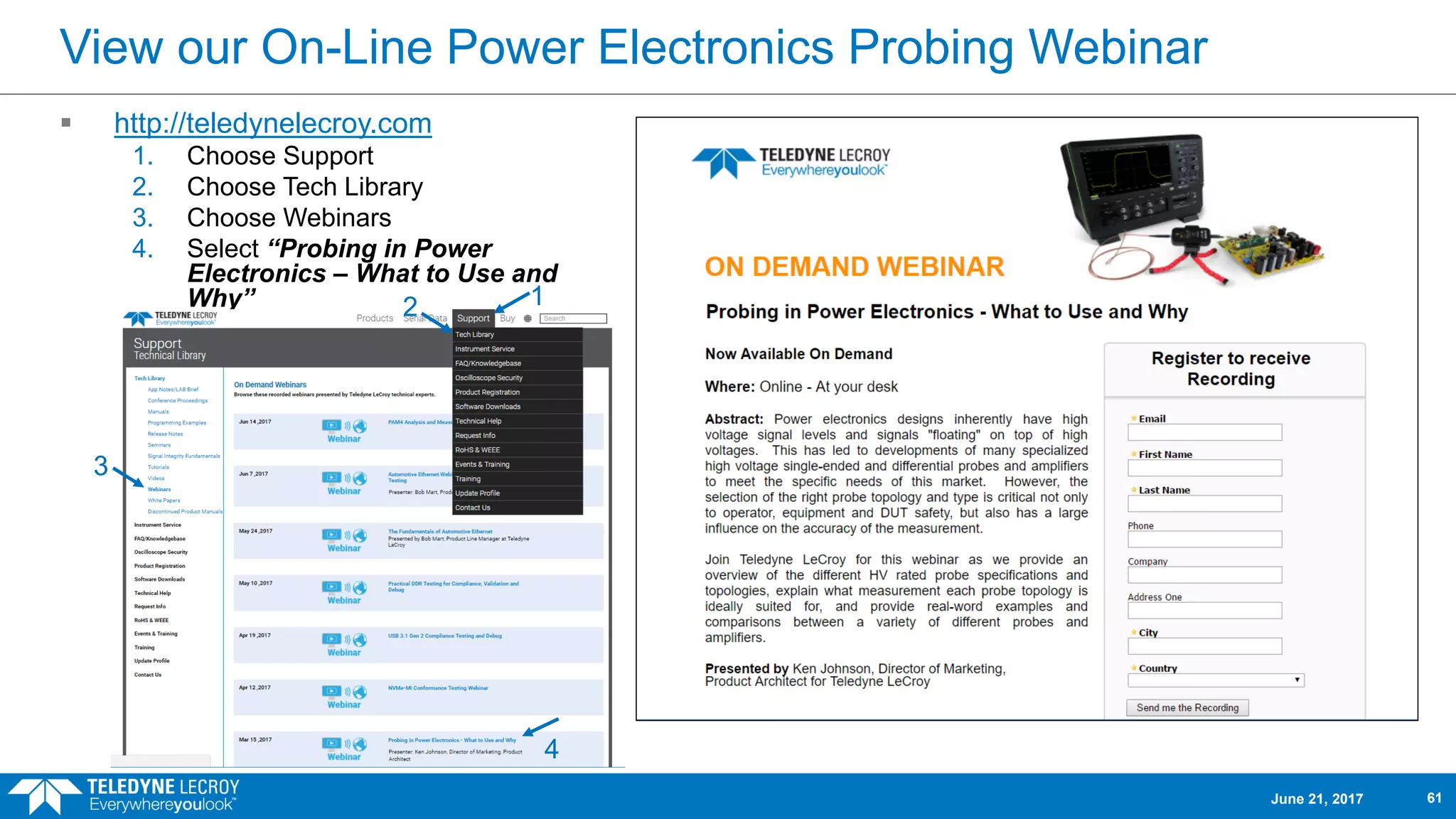
View our On-LinePower Electronics Probing Webinar
http://teledynelecroy.com
1. Choose Support
2. Choose Tech Library
3. Choose Webinars
4. Select “Probing in Power
Electronics – What to Use and
Why”
June 21, 2017 61
12
3
4